

R&M Data Center Handbook
R&M Data Center Handbook
R&M Data Center Handbook

You also want an ePaper? Increase the reach of your titles
YUMPU automatically turns print PDFs into web optimized ePapers that Google loves.
www.datacenter.rdm.com<br />
If for visualization some noise is added, it becomes obvious that at faster data-transmission rates, the sensitivity to<br />
interference increases tremendously. As a result, the sensitivity to interference in the EMC area gets increasingly<br />
higher as the data-transmission rate increases.<br />
During 2008, a group of cable suppliers, including R&M, came together to compare the EMC behavior of various<br />
cabling types in a neutral environment. To ensure the independence and objectivity of the results, a 3rd party test<br />
laboratory was commissioned with the investigation, specifically the “Gesellschaft für Hochfrequenz Messtechnik<br />
GHMT” (“Organization for High Frequency Testing”) located in the German town of Bexbach. The goal of the<br />
study was to answer the following questions concerning the selection of the cabling system:<br />
• Which parameters must be estimated in order to draw meaningful conclusions about the EMC behavior<br />
of shielded and unshielded cabling systems<br />
• Which special measures are necessary when using shielded or unshielded cabling in order to ensure<br />
operation that conforms to legal requirements and standards<br />
• How does the EMC behavior of shielded and unshielded cabling compare during the operation of 1G and<br />
10GBase-T<br />
The basic idea was not to pit shielded and unshielded systems against each other, but rather to clearly indicate<br />
the basic conditions that must be adhered to in order to ensure problem-free operation of 10GBase-T that is in<br />
conformance with legal requirements. By doing so, assistance can be offered to planners and end customers so<br />
they can avoid confusion and uncertainty when selecting a cabling system.<br />
The results presented are exclusively those from the independent EMC study carried out by GHMT; the interpretation<br />
of the results and conclusions drawn are, however, based on analyses by R&M.<br />
Equipment under test and test set-up<br />
The examination of six cabling systems was planned:<br />
• 1x unshielded Cat 6<br />
• 2x unshielded Cat 6A<br />
• 3x shielded Cat 6A with shielded twisted pairs (foil) and different degrees of coverage of the braided<br />
shield (U-FTP without braided shield, S-STP “light” with moderate braided shield, S-STP with good<br />
braided shield).<br />
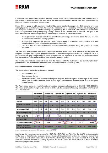
The Figure below shows the results from the antecedent measurements according to ISO/IEC 11801 (2008-04).<br />
The values given are the margin vs. the Class E A limits, with the exception of coupling attenuation, which is given<br />
as an absolute value.<br />
Cable parameters in accordance with ISO/IEC 11801 (2008-04)<br />
Surprisingly, the transmission parameters (IL, NEXT, PS NEXT, TCL and RL) of the Cat 6A UTP systems are at a<br />
similar level as those from the shielded systems. Except with the older Cat 6 system, the values are more or less<br />
comparable to each other. Noticeable is that the PS ANEXT requirements are barely reached, if at all, by the<br />
unshielded systems. As soon as shielding is present, the ANEXT values are improved 30 to 40 dB so much that<br />
they no longer present a problem.<br />
R&M <strong>Data</strong> <strong>Center</strong> <strong>Handbook</strong> V2.0 © 08/2011 Reichle & De-Massari AG Page 149 of 156