EGAS41 - Swansea University
EGAS41 - Swansea University
EGAS41 - Swansea University

Create successful ePaper yourself
Turn your PDF publications into a flip-book with our unique Google optimized e-Paper software.
41 st EGAS CP 170 Gdańsk 2009<br />
Laser-driven Cs magnetometer arrays for cardiomagnetic field<br />
imaging<br />
M. Kasprzak 1,∗ , G. Bison 2 , N. Castagna 1 , A. Hofer 1 ,<br />
P. Knowles 1 , J.-L. Schenker 1 , A. Weis 1<br />
1 Department of Physics, <strong>University</strong> of Fribourg,<br />
Chemin du Musée 3, CH–1700 Fribourg, Switzerland<br />
2 Department of Neurology, Friedrich-Schiller-<strong>University</strong>,<br />
Erlanger Allee 101, D–07747 Jena, Germany<br />
∗ Corresponding author: malgorzata.kasprzak@unifr.ch<br />
Magnetocardiography is an innovative diagnostic method for cardiac diseases, based on<br />
the measurements of the weak magnetic fields (50–100 pT amplitude) produced by the<br />
electrical activity of a human heart. In current practice, magnetometers based on superconducting<br />
quantum interference devices (SQUIDs), which require cooling to 4 K,<br />
are the sensor of choice. However, due to the high capital investment and maintenance<br />
costs of such devices, there is a need and an interest in alternative methods of heart<br />
field detection. This issue has been investigated by the Fribourg Atomic Physics Group<br />
(FRAP) and resulted in the development of an optical Cs magnetometry system adapted<br />
to the heart measurement problem [1,2]. The magnetometer sensors record the Larmor<br />
precession frequency of Cs atoms in paraffin-coated vapor cells (28 mm diameter) via<br />
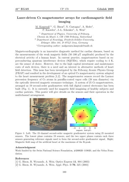
the optically detected magnetic resonance technique. A system of 25 Cs magnetometers,<br />
arranged as 19 second-order gradiometers with full digital control electronics has been<br />
built (Fig. 1). It is currently used for magnetic field imagining of healthy subjects and<br />
cardiac patients. This poster will give details on the sensors and their operation in the<br />
multichannel arrangement.<br />
Figure 1: Left: The 19 channel second-order magnetic gradiometer system using 25 mounted<br />
sensors. The lowest plane contains 19 sensors, and the two upper planes contain each three<br />
sensors generating reference signals used to form the second-order gradiometer signal. Right:<br />
Magnetic field map of the artificial heart at the maximum of the R-peak.<br />
Acknowledgment<br />
Work funded by the Swiss National Science Foundation, #200020–119820, and the Velux Foundation.<br />
References<br />
[1] G. Bison, R. Wynands, A. Weis, Optics Express 11, 904 (2003)<br />
[2] G. Bison, R. Wynands, A. Weis, Appl. Phys. B 76, 325 (2003)<br />
230