Blackmagic ATEM Manual - Concept Music Art
Blackmagic ATEM Manual - Concept Music Art
Blackmagic ATEM Manual - Concept Music Art

Create successful ePaper yourself
Turn your PDF publications into a flip-book with our unique Google optimized e-Paper software.
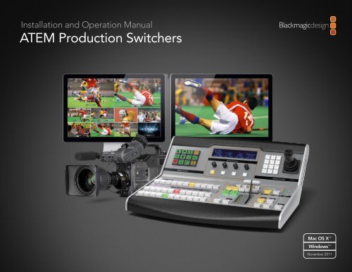
Installation and Operation <strong>Manual</strong><br />
<strong>ATEM</strong> Production Switchers<br />
Mac OS X <br />
Windows <br />
November 2011
Welcome<br />
Welcome to <strong>ATEM</strong> Live Production!<br />
Thank you for purchasing an <strong>ATEM</strong> switcher for your live production work!<br />
If you’re new to live production switchers, then you’re about to become involved in the most exciting part<br />
of the television industry and that’s live production! There is nothing like live production and it’s so easy<br />
to become addicted to the adrenaline rush of editing in real time while the live event unfolds before your<br />
eyes. It’s real television the way it should be!<br />
Previously broadcast quality live production has always been way too high in cost for most people to afford,<br />
while affordable switchers lacked broadcast features and quality. The new <strong>ATEM</strong> switchers change this, and<br />
you can use them for the most amazing professional live production results. We hope you get years of use<br />
from them and have lots of fun with your live production!<br />
Not only does this <strong>ATEM</strong> switcher include all the features and SDI connections that broadcasters demand<br />
but you also get loads of HDMI connections so you can get started with low cost HDMI HD cameras and<br />
televisions. This really reduces cost and lets you build your business while adding additional equipment<br />
as you grow.<br />
This instruction manual should contain all the information you’ll need for installing your <strong>ATEM</strong> Production<br />
Switcher. The <strong>ATEM</strong> switcher includes a software control panel which you can run on your computer or<br />
you can purchase a hardware based broadcast control panel separately. The computer and control panels<br />
connect to your <strong>ATEM</strong> switcher via a network cable and you can directly connect them together without<br />
any extra equipment!<br />
Please check the support page on our web site at www.blackmagic-design.com for the latest version of<br />
software for your <strong>ATEM</strong> switcher. Simply connect your computer to the <strong>ATEM</strong> switcher and the <strong>ATEM</strong><br />
broadcast control panel via USB to update software so you get all the latest features! When downloading<br />
software, please register with your information so we can keep you updated when new software is released.<br />
We are constantly working on new features and improvements, so we would love to hear from you!<br />
Grant Petty<br />
CEO <strong>Blackmagic</strong> Design
Contents<br />
<strong>ATEM</strong> Production Switchers<br />
5<br />
Getting Started<br />
Introducing <strong>ATEM</strong> 5<br />
What is an M/E Switcher 5<br />
Understanding the <strong>ATEM</strong> Processor Chassis 8<br />
Plugging in Multi View Monitoring 9<br />
Plugging in a Control Panel 10<br />
Installing <strong>Blackmagic</strong> <strong>ATEM</strong> Software on Mac OS X 11<br />
Installing <strong>Blackmagic</strong> <strong>ATEM</strong> Software on Windows 7 12<br />
Plugging in your Computer 13<br />
Settings You Need To Check! 14<br />
Plugging in Cameras 15<br />
Connecting to a Network 16<br />
Changing the Switcher Network Settings 17<br />
Understanding the Broadcast Panel Network Settings 17<br />
Setting the Broadcast Panel to Find the Switcher IP Location 18<br />
Changing the Broadcast Panel Network Settings 19<br />
Button Mapping 20<br />
Saving Switcher Settings 20<br />
Sending Tally Signals via a GPI and Tally Interface 21<br />
25<br />
27<br />
Connecting Video Outputs<br />
Using <strong>ATEM</strong> Software Control<br />
Interface Overview 27<br />
Switcher Control Panel 27<br />
Media Manager 28<br />
Switcher Settings 29<br />
Using the Software Control Panel 29<br />
Mix Effects 29<br />
Program Bus Source Select Buttons 30<br />
Preview Bus Source Select Buttons 30<br />
Transition Control and Upstream Keyers 30<br />
Downstream Keyers 32<br />
Fade to Black (FTB) 32<br />
Processing Palettes 32<br />
Using the Media Manager and Media Pool 34<br />
Changing Switcher Settings 36<br />
Controlling Auxiliary Outputs 39<br />
23<br />
Updating the Software<br />
How to Update the <strong>ATEM</strong> Software! 23<br />
Updating the Switcher Chassis Software 23<br />
Updating the Broadcast Control Panel Software 24
Contents<br />
<strong>ATEM</strong> Production Switchers<br />
40<br />
45<br />
Using the <strong>ATEM</strong> 1 M/E Broadcast Panel<br />
Control Panel Overview 40<br />
Using the Control Panel 40<br />
Mix Effects 40<br />
Source Names Display 40<br />
Program Bus 40<br />
Preview Bus 41<br />
SHIFT 41<br />
Destination Display and Select Bus 41<br />
Transition Control and Upstream Keyers 41<br />
Downstream Keyers 43<br />
Fade to Black 43<br />
System Status 44<br />
System Control 44<br />
Menu Buttons 44<br />
Joystick and Numeric Keypad 44<br />
Operating Your <strong>ATEM</strong> Switcher<br />
89<br />
97<br />
<strong>Manual</strong> Transitions 65<br />
Preview Transition 66<br />
Keying on <strong>ATEM</strong> Switchers 67<br />
Understanding Keying 67<br />
Using Adobe Photoshop with <strong>ATEM</strong> 85<br />
Setting up Plug-in Switcher Location 85<br />
Preparing Graphics for Download 85<br />
Using Auxiliary Outputs 86<br />
Using USB 3.0 Connection 88<br />
<strong>Blackmagic</strong> Media Express<br />
What is Media Express 89<br />
Capturing Video and Audio Files 90<br />
Playing Back Video and Audio Files 94<br />
Browsing Media 95<br />
<strong>Blackmagic</strong> UltraScope<br />
Internal Video Sources 45<br />
Black 45<br />
Color Bars 45<br />
Color Generators 45<br />
Media Players 45<br />
109<br />
What is UltraScope 97<br />
Installation Requirements for Windows 97<br />
<strong>Blackmagic</strong> UltraScope Interface 98<br />
Help<br />
Cut Transitions 47<br />
USB 3.0 Frequently Asked Questions 110<br />
Auto Transitions 49<br />
112<br />
Warranty Information
5<br />
Getting Started<br />
Introducing <strong>ATEM</strong><br />
The <strong>ATEM</strong> 1 M/E Production Switcher is a professional broadcast grade digital production switcher capable<br />
of switching and creatively processing a variety of video sources in live video production and broadcast<br />
environments. The switcher uses a familiar M/E (Mix Effects) based design with software and hardware<br />
control options that provides a familiar, fast and easy to use workflow!<br />
An <strong>ATEM</strong> production switcher only requires an <strong>ATEM</strong> production switcher chassis and the included software<br />
control panel to get started. Then you can optionally add one or more hardware control panels if you need<br />
a more advanced solution.<br />
Multiple control panels can be connected to control the same switcher chassis by simple ethernet<br />
connections. The <strong>ATEM</strong> software control panel can be installed on as many computers as you like at no<br />
extra cost.<br />
What is an M/E Switcher<br />
If you have used low cost switchers before, then these might not have used the mix effects style of operation<br />
that’s commonly called an M/E style of operation. If you have used an M/E style switcher, then you might<br />
want to skip ahead to install and get working with your new <strong>ATEM</strong> switcher!<br />
When you’re starting out with a switcher for the first time, the <strong>ATEM</strong> can look a little intimidating with all its<br />
buttons and knobs, however it's all very logically laid out so it's very simple to use!<br />
<strong>ATEM</strong> is a true high-end broadcast switcher that operates using the M/E workflow standards used in the<br />
broadcast industry. This means once you get familiar with how it works, you will feel instantly at home on<br />
virtually any switcher used in broadcast today.<br />
The M/E style of operation has been developed over decades to help eliminate errors when switching live<br />
events and is a broadcast standard. It's extremely easy to see what's going on at any time so you don't get<br />
confused and make mistakes. The M/E style of operation lets you check the sources you are about to switch<br />
on air, as well as try effects before using them on air. You can see buttons for each keyer and transition, so<br />
you instantly know what's going on and what's about to happen.<br />
The best way to learn about how your <strong>ATEM</strong> works is to grab your switcher and play with it while referencing<br />
this manual! You might want to jump ahead and install your switcher before reading the rest of this section!<br />
To start, the most visible part of an M/E based control panel is the fader bar fader, and the program and<br />
preview rows of source buttons!
6<br />
Getting Started<br />
The program bus source select buttons are used to hot switch sources to the program output. The source<br />
currently on air is indicated by a button that is illuminated red. Be careful when selecting sources on this row,<br />
as they will instantly be switched on air!<br />
A better and more orderly way to do transitions is to select them on the preview row, and then use a<br />
transition to cut or transition them on air.<br />
The bottom row of buttons is the preview bus source selection. This is where you will spend most of your<br />
time selecting sources about to go on air. This selected source is sent to the program output when the next<br />
transition occurs. The next transition can be triggered by pushing the cut button, the auto button, or by<br />
toggling the fader bar. You can select between a mix, dip, wipe, DVE or other transition depending what<br />
you have selected in the transition control section.<br />
This is a very powerful way to use a switcher, because you can select your source on the preview row, and see<br />
it on the preview video output to confirm that you have the correct source before you select the transition<br />
you want. You can see what's happening at all stages so it’s hard to make mistakes. Only the M/E style of<br />
operation allows you to keep track of what's going on.<br />
You also might notice that once your transition is complete, the sources selected on the preview and<br />
program rows swap over. This is because the source you selected on the preview row is now the new on<br />
air source, so it becomes selected on the program row once the transition is complete. Remember the<br />
program row always shows what's on air.<br />
You will also see both the program and preview buttons illuminate red when doing an auto transition, as for<br />
a short time, they are both on air while the transition occurs.<br />
There are multiple types of transitions available, and they can be selected in the transition control. On the<br />
<strong>ATEM</strong> 1 M/E Broadcast Panel there are two transition type buttons. One is labeled dip/mix and the other is<br />
labeled DVE/wipe. Hitting these buttons selects mix and wipe transitions, however pressing shift and then<br />
selecting mix or wipe allows more types of transitions, dip and DVE. You can also select both buttons for a<br />
stinger transition. If you are using the <strong>ATEM</strong> software control panel on your computer, all transition types<br />
have their own button, and no shifting in necessary to select any of them. Extra details on how all these<br />
transitions work are provided later in this instruction manual.<br />
The other concept that is important to know about M/E style switchers, including <strong>ATEM</strong>, is the video on the<br />
program and preview rows is technically called the background video. This is because the upstream (effects)<br />
keyers and downstream keyers will overlay on top of this source. So you can load graphics into the keyers<br />
and see them with the preview video and when keys are turned on, you will see the overlay on top of the<br />
program video. This is very powerful and allows multiple layers to be built up.
7<br />
Getting Started<br />
Another great advantage of the <strong>ATEM</strong> M/E style of operation is you can tie keyers to the transition. This<br />
means when you do a mix transition, you can also fade on or off keyers at the same time. This allows you to<br />
build up a composition, and then bring the whole lot on air at the same time. This is what the next transition<br />
buttons do, and you can select background for normal transitions, or select one or more keyers to transition<br />
them on air.<br />
You can even press multiple buttons on the hardware control panel to tie multiple keys and the background<br />
at the same time. There are also dedicated downstream key tie buttons to tie downstream keyers to the<br />
transition. Downstream keys also have dedicated cut and mix buttons and so are very flexible. Downstream<br />
keyers are always layered over the top of everything including the transition, so are a great place to key bugs<br />
and logos!<br />
Finally, when your live production is finishing, it's nice to have a dedicated fade to black (FTB) control to fade<br />
everything to black!. You can see the dedicated fade to black control on the right side of the keyboard. This<br />
lets you fade everything to black, and helps make sure you don't miss a layer. Fade to black is at the extreme<br />
end of the processing chain so you get a clean fade of all sources.<br />
The last part of an M/E style switcher is the select bus. This is above the program row, and simply allows<br />
sources to be selected for effects processing and other purposes, and there is a label above this to show<br />
what you’re switching. The select bus is commonly used to select key inputs, and aux. outputs. It's a clean<br />
switch, so when used to select aux. outputs, you get a clean cut.<br />
As you can see by this quick overview, M/E style of operation allows confident live production with<br />
good feedback on what's going on and the state of your switcher and programming at any point in your<br />
production. Once you learn M/E style of operation, you can move between models of production switchers<br />
with little retraining as they all work the same!
8<br />
Getting Started<br />
<strong>ATEM</strong> Television Studio<br />
<strong>ATEM</strong> 1 M/E Production Switcher Chassis<br />
<strong>ATEM</strong> 2 M/E Production Switcher Chassis<br />
Understanding the <strong>ATEM</strong> Processor Chassis<br />
The <strong>ATEM</strong> processor chassis provides all the video processing as well as all video input and output connectors,<br />
connection for control panels and power connections. You use the <strong>ATEM</strong> switcher by connecting and using<br />
various types of control panels. This allows the switcher to be located remotely, such as in machine rooms<br />
where it's closer to the connected video devices, while the control panel can be placed in a location from<br />
where it is easier to run production.<br />
The Television Studio is capable of switching 6 external inputs from its SDI and HDMI input connectors.<br />
Input 3 and 4 are selectable between HDMI and SDI, which can be set in the <strong>ATEM</strong> software control panel<br />
settings tab.<br />
The 1 M/E model of switcher is capable of switching 8 external inputs from its analog, SDI and HDMI input<br />
connectors. Input 1 is selectable between the HDMI Input 1 connector and the analog component Input 1<br />
connector and is set in the <strong>ATEM</strong> software control panel settings tab.<br />
The 2 M/E model of switcher is capable of switching 16 external inputs from its analog, SDI and HDMI input<br />
connectors. Input 1 is selectable between the HDMI Input 1 connector and the analog component Input 1<br />
connector and is set in the <strong>ATEM</strong> software control panel settings tab.<br />
The <strong>ATEM</strong> chassis mounts in a standard 19" rack. The Television Studio is only 1 rack unit high while the 1<br />
M/E is only 2 rack units and the 2 M/E is only 3 rack units high. The <strong>ATEM</strong> chassis is very thin and so is ideal<br />
for either fixed installation or portable use. You can mount at the front or back of a rack to save space.<br />
When running your <strong>ATEM</strong>, you might notice the <strong>ATEM</strong> processor chassis feels warm to the touch. This is<br />
because the internal microprocessors are connected to the rear mounted heat sink via the metal chassis.<br />
This causes heat to spread out over the metal chassis, however your <strong>ATEM</strong> chassis is not overheating.<br />
This design eliminates noisy fans, so is more reliable, and you won't get noise into your microphones.
9<br />
Getting Started<br />
Plugging in Multi View Monitoring<br />
The <strong>ATEM</strong> switcher chassis can be a little intimidating when first seen, because it has no controls to access,<br />
just lots of connectors! So the first step is to plug in the power, and a monitor, to see it working!<br />
A fantastic way to check that your <strong>ATEM</strong> is powered on and working correctly is to plug in a HDMI television<br />
into the Multi View output on the right side of the heat sink on the <strong>ATEM</strong> rear panel. You should see 8 video<br />
boxes at the bottom, and two larger boxes at the top, all bound by white borders. Each box will have a label.<br />
If you see this video output, then your <strong>ATEM</strong> switcher is powered on and running fine! All you need to do<br />
now is plug in some control panels and video sources so you can start using your switcher!<br />
If you don't see the multi view output on your television, then check the connections and cables are correct.<br />
You need to plug into the multi view connector on the rear of the <strong>ATEM</strong> chassis. Next check your television is<br />
compatible with 1080i59.94 video, as your <strong>ATEM</strong> defaults to that video standard when new. If your television<br />
is not compatible with 1080i59.94, then don't worry, as it's easy to change once we connect your computer<br />
to the <strong>ATEM</strong> chassis.<br />
If you still don't see the multi view on your television, then double check your power connection to make<br />
sure your <strong>ATEM</strong> is powered on.
USB 2.0<br />
BACKUP 12V POWER<br />
MAIN 12V POWER<br />
ETHERNET 2 ETHERNET 1<br />
10<br />
Getting Started<br />
Plugging in a Control Panel<br />
If you have purchased an <strong>ATEM</strong> Broadcast Panel, then you won't want to wait to plug in your computer, as<br />
it's much more fun to plug in the hardware panel first!<br />
Plugging in the <strong>ATEM</strong> Broadcast Panel is simple, because it's already set to the correct network settings to<br />
plug into your <strong>ATEM</strong> processor chassis without any changes required.<br />
Step 1.<br />
Plug in the power to the <strong>ATEM</strong> Broadcast Panel. If you want redundant power supplies, then you<br />
can purchase a second power supply and plug that into the second power connector.<br />
Step 2. Plug one end of an ethernet cable into one of the control panel’s ethernet ports. Either of the<br />
ports will do, as there is an ethernet switch inside the panel, so both ports work the same.<br />
Step 3. Plug the other end of the same cable into the ethernet port on the <strong>ATEM</strong> processor chassis<br />
labeled switcher control.<br />
If everything is working fine, you should see the lights on the ethernet port start to flicker, and the panel<br />
should come alive with buttons illuminated, and the main display on the panel should say <strong>ATEM</strong> Production<br />
Switcher.<br />
If you don't see this appear, then check the <strong>ATEM</strong> processor chassis and the control panel are powered<br />
correctly and the cables are screwed in tight.<br />
If things are still not working, then you should make sure you are not plugged into a network, and that your<br />
panel is connected directly to your <strong>ATEM</strong> switcher processor chassis. If this is correct, then the most likely<br />
cause of the problem is the switcher and the chassis have different IP addresses. In this case, you will need<br />
to check and set these as described later in this manual.<br />
If you need to manually set the network settings, then you might need to get the assistance of a technically<br />
minded friend who understands how to set IP addresses. By default, the <strong>ATEM</strong> processor chassis is set to a<br />
fixed IP address of 192.168.10.240, and the <strong>ATEM</strong> Broadcast Panel is set to fixed IP of 192.168.10.10, so when<br />
connected directly they should communicate without any problems. Go to the connecting to the network<br />
section in this manual to see how to check and set your switcher to these addresses. Then it should work ok<br />
with a direct connection between the panel and the switcher processor chassis.
11<br />
Getting Started<br />
Installing <strong>Blackmagic</strong> <strong>ATEM</strong> Software on Mac OS X<br />
Before installing any software you will need administrator privileges.<br />
Step 1.<br />
Ensure you have the very latest driver. Visit www.blackmagic-design.com/support<br />
Step 2. Open the “<strong>Blackmagic</strong> <strong>ATEM</strong> Switchers” folder from the disc or downloaded disk image and<br />
launch the “<strong>Blackmagic</strong> <strong>ATEM</strong> Switchers Installer”.<br />
Step 3.<br />
Step 4.<br />
Click Continue, Agree and Install buttons and the software will be installed on your system.<br />
Now restart your computer to enable the new software drivers.<br />
Follow install prompts.<br />
Plugins and Applications that are Installed<br />
The <strong>ATEM</strong> Switchers software installs the following components which are used by <strong>ATEM</strong> Switchers:<br />
• <strong>ATEM</strong> Software Control<br />
• <strong>ATEM</strong> Setup Utility<br />
• <strong>Blackmagic</strong> Desktop Video drivers<br />
• <strong>Blackmagic</strong> Media Express<br />
The <strong>ATEM</strong> Switchers software also installs additional <strong>Blackmagic</strong> Desktop Video components which are<br />
used by other <strong>Blackmagic</strong> Design capture products when installed on the same computer:<br />
On Mac OS X, all the files needed to run your <strong>ATEM</strong> switcher will be installed into a folder called <strong>Blackmagic</strong><br />
<strong>ATEM</strong> Switchers in the Applications folder.<br />
In this <strong>Blackmagic</strong> <strong>ATEM</strong> Switchers folder, you will see <strong>ATEM</strong> Software Control, which is the software control<br />
panel for your switcher, and also allows loading graphics into the switcher media pool and changing settings.<br />
The <strong>ATEM</strong> Setup Utility allows you to change the switcher IP address, or update the switcher and panel<br />
software via USB. Also included in this folder is this instruction manual and some example graphics. Use the<br />
example graphics to explore the internal media pool and keying functionality.<br />
In the Applications folder, you will see <strong>Blackmagic</strong> Media Express which allows you to capture the Program<br />
Output of <strong>ATEM</strong> Television Studio to H.264 files.
12<br />
Getting Started<br />
Installing <strong>Blackmagic</strong> <strong>ATEM</strong> Software on Windows 7<br />
Step 1.<br />
Ensure you have the very latest driver. Visit www.blackmagic-design.com/support<br />
Step 2. Open the “<strong>Blackmagic</strong> <strong>ATEM</strong> Switchers” folder and launch the “<strong>Blackmagic</strong> <strong>ATEM</strong> Switchers<br />
Installer”.<br />
Step 3.<br />
The software will now be installed on your system. An alert will appear: “Do you want to allow the<br />
following program to install software on this computer” Click Yes to continue.<br />
Step 4. You will see a dialog bubble saying “found new hardware” and the hardware wizard will appear.<br />
Select “install automatically” and the system will find the required Desktop Video drivers. You will<br />
then receive another dialog bubble saying “your new hardware is ready for use.”<br />
Step 5.<br />
Now restart your computer to enable the new software drivers.<br />
Follow install prompts.<br />
Plugins and Applications that are Installed<br />
The <strong>ATEM</strong> Switchers software installs the following components which are used by <strong>ATEM</strong> Switchers:<br />
• <strong>ATEM</strong> Software Control<br />
• <strong>ATEM</strong> Setup Utility<br />
• <strong>Blackmagic</strong> Desktop Video drivers<br />
• <strong>Blackmagic</strong> Media Express<br />
• <strong>Blackmagic</strong> UltraScope<br />
The <strong>ATEM</strong> Switchers software also installs additional <strong>Blackmagic</strong> Desktop Video components which are<br />
used by other <strong>Blackmagic</strong> Design capture products when installed on the same computer:<br />
Once the computer has restarted, all the <strong>ATEM</strong> software applications will be installed and can be accessed<br />
from Start > Programs > <strong>Blackmagic</strong> Design.<br />
In the <strong>ATEM</strong> Switchers folder, you will see the <strong>ATEM</strong> Software Control, which is the software control panel for<br />
your switcher, which also allows loading graphics into the switcher media pool and changing settings. The<br />
<strong>ATEM</strong> Setup Utility allows you to change the switcher IP address, or update the switcher and panel software<br />
via USB. Also included in this folder is this instruction manual and some example graphics. Use the example<br />
graphics to explore the internal media pool and keying functionality.<br />
In the Media Express folder, you will see <strong>Blackmagic</strong> Media Express which allows you to capture the<br />
Program Output of <strong>ATEM</strong> Television Studio to H.264 files. Media Express also allows you to capture the<br />
uncompressed Aux 1 output of <strong>ATEM</strong> 1 M/E Production Switcher via USB 3.0, which is perfect for post<br />
production. In the UltraScope folder, you will see <strong>Blackmagic</strong> UltraScope which allows you to perform live<br />
waveform monitoring of the Aux 1 output of <strong>ATEM</strong> 1 M/E Production Switcher via USB 3.0.
13<br />
Getting Started<br />
Plugging in your Computer<br />
You can plug your computer directly into the <strong>ATEM</strong> switcher so you can control the switcher, load the media<br />
pool with graphics and clips, and change switcher settings.<br />
You will need to connect a computer otherwise you cannot change settings such as the switcher video<br />
standard, as well as down conversion modes, input video connections and labels, as well as customizing<br />
the multi view.<br />
Connecting your computer is easy and after installing the <strong>ATEM</strong> Switcher Software simply follow the<br />
directions below:<br />
Step 1.<br />
Step 2.<br />
Connect an Ethernet cable from the chassis ethernet port labeled Switcher Control to the Ethernet<br />
port of your computer.<br />
If you have a hardware panel installed, and already have this connected to your <strong>ATEM</strong>, then plug<br />
your computer into the second ethernet port on your hardware panel instead. Now the computer<br />
will talk via your panel to the switcher, and both the hardware panel and this software control<br />
panel can be operated in parallel.<br />
Ensure your <strong>ATEM</strong> switcher is powered on.<br />
Step 3. In the network settings on your computer, enable ethernet, and set the IP address setting to<br />
manual. Then enter the IP address 192.168.10.50.<br />
Now when you run your <strong>ATEM</strong> Software Control you should see the buttons on the control tab light up and<br />
show the switcher state after a slight pause.<br />
If you’re more technically minded and want to connect your <strong>ATEM</strong> switcher to your network, then you will<br />
need to change the network settings on your <strong>ATEM</strong> switcher and control panel. Information on how to do<br />
this is available in the next section. You will need to manually set the IP address for the switcher chassis as<br />
well as all control panels to match your network IP address range. Your <strong>ATEM</strong> switcher defaults to a fixed<br />
IP address of 192.168.10.240 when shipped and, by using the <strong>ATEM</strong> Setup Utility, you can customize the IP<br />
address for your custom network configuration.<br />
Set IP Address for your Computer
14<br />
Getting Started<br />
Settings You Need To Check!<br />
Now you have the software control working, you need to change some settings to use your <strong>ATEM</strong> switcher.<br />
The changes are made in the settings tab of the <strong>ATEM</strong> Software Control and the most critical settings are<br />
listed below:<br />
Set Video Standard<br />
Check 1. Set the switcher video standard<br />
<strong>ATEM</strong> defaults to 1080i59.94 when purchased, however you might want to select another video<br />
standard if you’re working in Europe or Asia. 1080i59.94, 720p59.94 and NTSC is common in the<br />
US and Japan, while in Europe and Asia, 1080i50, 720p50, or PAL is more common.<br />
You need to make sure all your cameras and any connected HDMI devices are also set to the<br />
same video standard, or they won't be visible on the switcher video inputs. This means you need<br />
to standardize on a specific video standard for all your equipment. This is generally quite easy,<br />
as countries have standards for their HD broadcasts and all equipment sold in these countries<br />
matches this standard or at the very least can be switched between standards. When all video<br />
standards are matched, you should see connected devices show up in the multi view video input<br />
windows.<br />
Set Video Inputs and Labels<br />
Check 2. Set and label the video input settings<br />
Different models of <strong>ATEM</strong> switchers allow some inputs to change between multiple connections<br />
on the rear panel. For example on the <strong>ATEM</strong> 1 M/E Production switcher model, input 1 can be<br />
switched between HDMI and analog component.<br />
While you’re setting inputs, you might also want to change the input labels. These labels appear<br />
on the multi view and the hardware panel. There are two labels to change: a long label used in<br />
software, and the short label that's limited to 4 digits and used in the hardware control panel.<br />
Check 3. Customize the multi view<br />
There are 8 input views in the multi view, and you can select from a range of external and internal<br />
sources to display on these views. Simply click the menus to select what you want on each view. If<br />
you don't have 8 cameras on your job, then you can even select media players, color generators,<br />
or aux. outputs on these views. It's extremely flexible, and you can also change the multi view<br />
layout to suit your preference.<br />
Customize the Multi View
15<br />
Getting Started<br />
Plugging in Cameras and Other Video Sources<br />
Now you’re ready to plug in cameras! All you need to do is connect a cable from the camera video output,<br />
either HDMI or SDI, and then connect it to an input on the <strong>ATEM</strong> switcher chassis.<br />
Each connector on the rear chassis has an input label so you can see what camera is what input when viewed<br />
on the multi view and the control panel. If all your cameras are using the same video standard as set in your<br />
switcher, you will see each camera appear as you plug them in.<br />
You don't need to worry about genlock for cameras, because each input of your <strong>ATEM</strong> switcher has a<br />
full frame re synchronizer. If the <strong>ATEM</strong> switcher detects at any time that a video source is out of sync, it<br />
will automatically enable the frame sync so the input is clean for use. The frame sync function also allows<br />
consumer cameras to be connected to your <strong>ATEM</strong>, and using consumer cameras is a great way to get<br />
started because the latest HDMI based consumer HD cameras are now very affordable, and give quite<br />
nice HD. This lets you spend your money on more cameras, and then as you grow, you can start adding<br />
professional SDI based cameras.<br />
If you’re plugging in a computer to the HDMI inputs of the <strong>ATEM</strong> switcher, then be sure that the monitor<br />
settings on the computer are set to the correct resolution and frame rate. If you’re using 1080i video, then<br />
your monitor needs to be 1920 x 1080 resolution. If you’re running 720p on your switcher, then your monitor<br />
needs to be set to 1280 x 720 in resolution. If you are using NTSC then your monitor needs to be 720 x 486.<br />
If you are using PAL then your monitor needs to be set to 720 x 576. The frame rates also need to match.<br />
It's important to know that HDMI cable quality can vary, so we recommend buying good quality cables, and<br />
high end video resellers will stock a range of high quality cables. Good quality cables will help eliminate<br />
unwanted sparkle or glitches in HDMI video inputs.<br />
If you don't see video on a HDMI video input, even though you have a device connected, then you might<br />
want to check if the HDMI device you have connected uses HDCP content protection. This content<br />
protection actually encrypts the video data in the HDMI video cable, so the manufacturer does not allow<br />
the content to be seen on anything other than a television, so you won't be able to see images from these<br />
devices. Devices with HDCP content protection include DVD payers, and set top box's.<br />
In general, cameras and computers don't have content protection, so you should not have any problems<br />
connecting these devices. Some gaming consoles don't include HDCP content protection, however<br />
generally these are only the developer versions of these gaming consoles. Using the analog component<br />
input on your <strong>ATEM</strong> switcher to connect devices is a good work around in these situations.<br />
Please always be sure you have copyright ownership before using content, or displaying content publicly.
16<br />
Getting Started<br />
Connecting to a Network<br />
If you want to connect your <strong>ATEM</strong> switcher to a larger ethernet network, then you will most likely need<br />
to change the network settings on your <strong>ATEM</strong> switcher. Most people simply plug their computer and<br />
control panel direct to the <strong>ATEM</strong> chassis, however in some situations it can be very powerful to connect<br />
via your network!<br />
Your <strong>ATEM</strong> ships from the factory with settings to allow hardware control panels to simply be connected<br />
directly with an ethernet cable. However your <strong>ATEM</strong> supports full ethernet IP protocols so you can place<br />
your switcher and panel on your network or anywhere on the planet using the internet.<br />
However it's worth noting that if you use your <strong>ATEM</strong> on a network, then you’re also increasing the complexity<br />
of the connection between your control panel and the switcher, so there is possibly a greater chance of<br />
something going wrong. However <strong>ATEM</strong> can be used when plugged into a switch, and even via most VPN's<br />
and over the internet.<br />
To allow communication over ethernet, the IP addresses of the switcher chassis, broadcast panel and any<br />
computer's running the <strong>ATEM</strong> Software Control Panel need to be configured correctly. The IP address used<br />
for each device will depend on the IP address range of the network you’re plugging into.<br />
The <strong>ATEM</strong> switcher chassis always needs a fixed IP address so control panels have a stable location to<br />
connect to. This means you need to find a free fixed IP address in the range of your network that you<br />
can use.<br />
The control panels can be set to DHCP or fixed IP addresses. Generally when used on a network, the<br />
control panel would be selected to DHCP, so it is automatically assigned an IP address when connected to<br />
the network.<br />
For all devices to communicate, they must share the same IP address subnet, which means the first 3 fields<br />
in the IP address need to be the same. Each device must also use a unique IP address.<br />
Please remember to set all devices to the correct IP address so they can all communicate. You will need to<br />
set the IP address of the <strong>ATEM</strong> Production Switcher via USB using the <strong>ATEM</strong> Setup Utility. You will need to<br />
set the DHCP or fixed IP mode on the <strong>ATEM</strong> Broadcast Panel and if using a fixed IP address on the panel,<br />
set the IP address on the panel. You will also need to set the panel, switcher address to the new IP address<br />
you have just set for the switcher.<br />
Lastly, you need to ensure your computer is connected and working on your network. Then when you launch<br />
the <strong>ATEM</strong> Software Control application, you will be prompted automatically to enter in an IP address for<br />
the switcher if <strong>ATEM</strong> Software Control cannot communicate with the <strong>ATEM</strong> processor chassis. Use the IP<br />
address you just entered in for the switcher processor chassis. Then the <strong>ATEM</strong> Software Control can find the<br />
switcher and communicate.
17<br />
Getting Started<br />
<strong>ATEM</strong> Setup Utility Connects via USB<br />
Changing the Switcher Network Settings<br />
The switcher network settings are changed using the <strong>ATEM</strong> Setup Utility via USB. Please follow the steps<br />
below:<br />
Step 1.<br />
Step 2.<br />
Connect the switcher chassis via USB, to the computer running the <strong>ATEM</strong> Setup Utility software.<br />
Launch the <strong>ATEM</strong> Setup Utility software.<br />
Step 3. The switcher's current IP address and other settings will be displayed in the window. If you only<br />
want to check the IP address and not change it, you can simply quit <strong>ATEM</strong> Setup Utility.<br />
Step 4.<br />
To change the IP address or any other settings, simply edit the numbers and then select apply.<br />
Step 5. A dialog box will prompt you to please power cycle your <strong>ATEM</strong> switcher. Turn off and on the<br />
power on the switcher and then press OK.<br />
Understanding the Broadcast Panel Network Settings<br />
A broadcast panel's network settings are configured from the network setup menu in the broadcast panel's<br />
system control. Along with its own IP address, the broadcast panel also needs to be configured with the<br />
network location of the switcher, so that communication between the two devices can be established over<br />
the ethernet connection. If the broadcast panel's network settings are correctly configured, you will see the<br />
panel light up and buttons turn on so you can control the switcher.<br />
If the broadcast panel is displaying a message looking for the switcher, then you will need to set the<br />
broadcast panel's network settings so that the broadcast panel and switcher share the same subnet, and<br />
the network location to which the broadcast panel is trying to connect, matches the switcher's IP address.
18<br />
Getting Started<br />
Home Menu<br />
<strong>ATEM</strong> 1 M/E Production Switcher<br />
Control Panel Connected OK<br />
Panel IP Address: 192.168.10.10<br />
Connecting to 192.168.10.240...<br />
Control Panel Not Connected<br />
Setting the Broadcast Panel to Find the Switcher IP Location<br />
To set the network location of the switcher on the broadcast panel, so the panel can find the switcher and<br />
communicate, simply follow these steps:<br />
Step 1.<br />
Step 2.<br />
Step 3.<br />
When there is no communication with the switcher, the NETWRK SETUP menu will appear on the<br />
broadcast panel system control. Select the NETWRK SETUP menu button.<br />
Select the SWITCHR IP menu button and use the knobs or the numeric keypad to edit each field<br />
as required.<br />
When a field is changed, SAVE and REVERT menu buttons become available. Select SAVE to save<br />
the changed IP address, or REVERT to ignore the changes and revert to the currently stored IP<br />
address.<br />
Step 4. If the switcher IP address setting is changed, selecting SAVE will apply the changes and the<br />
broadcast panel will attempt to establish communication with the switcher using the new IP<br />
address.<br />
This does not change the IP address of the switcher itself. It just changes where the control panel is looking<br />
to find the switcher. If the control panel cannot find the switcher, then you might need to check the switcher<br />
processor to see if it's been set correctly. To change the IP address of the switcher, connect the switcher via<br />
USB to a computer and run the <strong>ATEM</strong> Setup Utility software as described previously in this manual.
19<br />
Getting Started<br />
Change Network Settings from the System Control<br />
Changing the Broadcast Panel Network Settings<br />
Because the broadcast panel is also on the network and communicating with the switcher processor chassis,<br />
it also has network settings so it can connect to the network. These settings are different to the switcher IP<br />
address, which is just where the panel is looking to find the switcher. The panel network settings can be<br />
changed by following the steps below:<br />
Step 1.<br />
Step 2.<br />
On the broadcast panel system control menus, select the NETWRK SETUP menu button.<br />
If the broadcast panel has already established connection to the switcher, you can access the<br />
NETWRK SETUP menu from the HOME menu by pressing the SHIFT and CUT/FILL buttons<br />
simultaneously. This will reveal the NETWRK SETUP menu button so you can select the network<br />
settings.<br />
The broadcast panel's current IP address, net mask and gateway information is displayed.<br />
Step 3. The next step is to decide if you want the panel to use a fixed IP address or to be automatically<br />
assigned an IP address from a DHCP server. Select PANEL DHCP to set this using the soft keys on<br />
the main display.<br />
Step 4.<br />
If you’re connecting direct to a switcher without a network, then you won't have a DHCP server<br />
to assign an IP address automatically, so you will want to select fixed. <strong>ATEM</strong> Broadcast Panels are<br />
delivered with a fixed IP address set to 192.168.10.10, for a direct connection.<br />
However if your network has lots of computers that automatically assign IP addresses via DHCP,<br />
then you can also select DHCP on the panel so the panel can get its network information<br />
automatically. This is possible on the panel, and it's only the switcher chassis itself that always<br />
requires a fixed IP, as the switcher needs to be found by the control panels at a known fixed<br />
address on your network.<br />
If you select DHCP, your network settings will be complete because the panel network settings<br />
will be obtained from the network automatically.<br />
If you have elected to use a fixed IP address, you now need to set this IP address by selecting the<br />
PANEL IP menu button and use the knobs or the numeric keypad to edit each field as required.<br />
Changing this IP address may cause the panel to lose communication.<br />
Step 5. If the subnet mask and gateway address need to be set, then select the relevant buttons on the<br />
system control buttons to set and use knobs or the numeric keypad to edit.<br />
Step 6.<br />
When any settings have been changed, SAVE and REVERT menu buttons will become available.<br />
Select SAVE to save the changes to the new network settings, or REVERT to ignore the changes<br />
and revert to the current network settings.
20<br />
Getting Started<br />
Button Mapping<br />
<strong>ATEM</strong> software and hardware control panels support button mapping so you can assign your most<br />
important sources, especially cameras, to the most accessible buttons in the program and preview rows.<br />
Occasional sources can be assigned to less prominent buttons. Button mapping is set independently for<br />
each control panel so button mapping set on a software control panel will not affect the button mapping<br />
set on a hardware control panel.<br />
<strong>ATEM</strong> Software Control Button Mapping<br />
In <strong>ATEM</strong> Software Control, select Preferences from the File menu in Windows or from the <strong>ATEM</strong> Software<br />
Control menu in Mac OS X. The Preferences window will open and display a list of buttons for your <strong>ATEM</strong><br />
switcher. Each of these buttons has a pulldown menu listing the inputs and the name of each input.<br />
Select the desired input for each button and then click Ok.<br />
<strong>ATEM</strong> Software Control button mapping<br />
Button Mapping<br />
Selected Button Selected Input<br />
Button 1 Input 1<br />
Camera 1<br />
<strong>ATEM</strong> Broadcast Panel button mapping<br />
<strong>ATEM</strong> Broadcast Panel Button Mapping and Button Brightness Level<br />
Button Mapping on <strong>ATEM</strong> Broadcast Panels is easy. On the <strong>ATEM</strong> Broadcast Panel, go to the System<br />
Control block and press PANEL SETUP followed by BUTTON MAP. Once in the button map menu, you<br />
will notice the System Control window shows a Button number and an Input number. Turn the knob under<br />
Selected Button to select the desired button which you want to associate with an input. You can do the<br />
same thing by selecting the desired button in the Select row. The buttons in the Select row correspond to<br />
the buttons directly below them in the Preview and Program rows. Next, turn the knob under Selected Input<br />
to set an input for the selected button. Choose another button you wish to map and repeat until all the<br />
buttons are mapped with desired inputs.<br />
If you want to change the brightness of the buttons, press the BUTTON LEVEL button and rotate the knob<br />
under Brightness until the desired brightness level is seen.<br />
Once you have configured all the button settings, press the SAVE button to save the new button map and<br />
brightness level, or REVERT to discard changes.<br />
Saving Switcher Settings<br />
You can save many settings in your <strong>ATEM</strong> switcher to use them again whenever you restart your switcher.<br />
Saved settings include parameters in all keyers as well as colors and transitions. You can also use this feature<br />
to recall your aux output settings. When you have your switcher set up the way you want it, go to the File<br />
menu in <strong>ATEM</strong> Software Control and select Save Startup State. Now whenever you restart your switcher,<br />
it will start up with the saved settings by default. If you want to clear the startup state and revert to the factory<br />
settings on restart, go to the File menu and select Clear Startup State.
21<br />
Getting Started<br />
GPI and Tally Interface<br />
Sending Tally Signals via a GPI and Tally Interface<br />
Your <strong>ATEM</strong> switcher can send tally signals to monitors and cameras to make it clear which source is on the<br />
program output, i.e. which source is on air.<br />
Tally is commonly used to light the red light on top of a camera or monitor so the talent knows they are on<br />
air. Tally can also illuminate a border on a monitor such as a <strong>Blackmagic</strong> SmartView Duo or SmartView HD.<br />
The border allows production staff to know which camera is on air.<br />
The GPI and Tally Interface by <strong>Blackmagic</strong> Design, is an Ethernet device which provides eight mechanical<br />
relay contact closures to ground that can be used for tally. Tally signals are sent from the Ethernet port of<br />
your <strong>ATEM</strong> switcher to a GPI and Tally Interface on the same network as the switcher. By following the wiring<br />
guide on the back of the GPI and Tally Interface, a breakout cable can be connected to video equipment<br />
that supports contact closure tally signals, such as <strong>Blackmagic</strong> SmartView Duo and SmartView HD. Up to 8<br />
tally receiving devices can be supported with the GPI and Tally Interface.<br />
The GPI inputs are optical isolators which are triggered by connection to ground with a maximum of 5V<br />
at 14mA.<br />
The tally outputs are mechanical relay contact closures to ground with a maximum of 30V at 1A.<br />
The following table illustrates which tally signal is fired when a switcher input is selected on the program<br />
output.<br />
Program Output<br />
Tally signal<br />
Switcher Input 1 Tally 1<br />
Switcher Input 2 Tally 2<br />
Switcher Input 3 Tally 3<br />
Switcher Input 4 Tally 4<br />
Switcher Input 5 Tally 5<br />
Switcher Input 6 Tally 6<br />
Switcher Input 7 Tally 7<br />
Switcher Input 8 Tally 8
22<br />
Getting Started<br />
Changing the GPI and Tally Interface Network Settings<br />
The <strong>ATEM</strong> Setup Utility is used to configure the network settings in the GPI and Tally Interface so it will<br />
communicate with your <strong>ATEM</strong> switcher. The GPI and Tally Interface must be connected via USB in order to<br />
configure its settings with the <strong>ATEM</strong> Setup Utility.<br />
Step 1.<br />
Step 2.<br />
Step 3.<br />
Connect the GPI and Tally Interface to the same Ethernet network as your <strong>ATEM</strong> switcher.<br />
Connect the GPI and Tally Interface to a USB port on your computer and also connect the included<br />
power supply.<br />
Launch the <strong>ATEM</strong> Setup Utility.<br />
Network Settings for the GPI and Tally Interface<br />
Step 4. If your <strong>ATEM</strong> switcher connects directly to your computer or <strong>ATEM</strong> broadcast panel without<br />
an Ethernet network switch, choose to "Configure Address Using Static IP". The GPI and Tally<br />
Interface defaults to a fixed IP address of 192.168.10.2 when shipped and we suggest you use<br />
this number for simplicity. If you need to change to another static IP address, you will need to<br />
choose one that is in the same range as the <strong>ATEM</strong> switcher but which hasn't already been used<br />
by a switcher, panel, gateway or computer on your network. If you have used the default IP<br />
addresses documented in this manual, then the following IP addresses have already been taken<br />
or reserved and should not be used: 192.168.10.1, 192.168.10.2, 192.168.10.10, 192.168.10.50 and<br />
192.168.10.240. The GPI and Tally Interface can use any other IP address within the same range<br />
that hasn't already been allocated to another device on the network.<br />
If your <strong>ATEM</strong> switcher connects via an Ethernet network switch, you may wish to choose "Configure<br />
Address Using DHCP" as this setting automatically obtains the IP Address, Subnet Mask and<br />
Gateway information from your DHCP server.<br />
Step 5.<br />
Type in the IP address of your <strong>ATEM</strong> switcher in the "Switcher Address" field. Your <strong>ATEM</strong> switcher<br />
defaults to a fixed IP address of 192.168.10.240 when shipped and this is the number you should<br />
type in this field unless you have changed it.<br />
Step 6. Click "Apply". The white LED to the right of the USB port should stop flashing and remain on to<br />
indicate it has successfully found the <strong>ATEM</strong> switcher. The GPI and Tally Interface is now ready for<br />
use.<br />
Step 7.<br />
Close out of the <strong>ATEM</strong> Setup Utility and disconnect your USB cable.
23<br />
Updating the Software<br />
How to update the <strong>ATEM</strong> Software!<br />
From time to time <strong>Blackmagic</strong> Design will release new software for your <strong>ATEM</strong> switcher, with new features,<br />
bug fixes, and increased compatibility with third party software and video devices.<br />
To update your <strong>ATEM</strong> switcher with new software, you need to use the <strong>ATEM</strong> Setup Utility to connect to<br />
the <strong>ATEM</strong> processor chassis and panels via USB. This utility always checks the switcher software and lets you<br />
know if there is new software.<br />
Always update all your equipment at the same time so it's all running the same version of software.<br />
First, download the latest <strong>Blackmagic</strong> <strong>ATEM</strong> Switcher software and install it on your Mac or PC using the<br />
instructions listed previously in the Installing Software section of this manual. Once installed, the new<br />
software for your <strong>ATEM</strong> processor chassis and broadcast panel will be included in the <strong>ATEM</strong> Setup Utility.<br />
<strong>ATEM</strong> Setup Utility<br />
Updating the Switcher Chassis Software<br />
Step 1. Connect the switcher chassis via USB to your computer. The switcher chassis is equipped with<br />
a USB connector which can be connected to a computer's USB 2.0 or USB 3.0 port using a<br />
USB cable.<br />
Step 2.<br />
Step 3.<br />
Step 4.<br />
When upgrading software, make sure the switcher is the only <strong>ATEM</strong> device connected via USB to<br />
the computer running the setup utility software. If more than one <strong>ATEM</strong> device is connected, the<br />
switcher may not be recognized.<br />
Launch the <strong>ATEM</strong> Setup Utility software.<br />
If the switcher software requires updating, you will be prompted by a window asking if you would<br />
like to update the software. Select Update Now to initiate the update process. The update process<br />
may take a few minutes. Do not unplug power from the switcher during the software update.<br />
Once the software update is complete, a window will prompt you to cycle power on the switcher.<br />
Select OK and cycle power on the switcher.
24<br />
Updating the Software<br />
Updating the Broadcast Control Panel Software<br />
Step 1. Connect the broadcast panel via USB to your computer. The broadcast panel is equipped with<br />
a USB connector which can be connected to a computer's USB 2.0 or USB 3.0 port using a<br />
USB cable.<br />
Step 2.<br />
When upgrading software, make sure the broadcast panel is the only <strong>ATEM</strong> device connected<br />
via USB to the computer running the setup utility software. If more than one <strong>ATEM</strong> device is<br />
connected, the panel may not be recognized.<br />
Launch the <strong>ATEM</strong> Setup Utility software.<br />
Step 3. If the broadcast panel software requires updating, you will be prompted by a window asking<br />
if you would like to update the software. Select Update Now to initiate the update process.<br />
The update process may take a few minutes. Do not unplug power from the panel during the<br />
software update.<br />
Step 4.<br />
Once the software update is complete, a window will prompt you to cycle power on the broadcast<br />
panel. Select OK and cycle power on the broadcast panel.
25<br />
Connecting Video Outputs<br />
There are multiple video outputs on your <strong>ATEM</strong> switcher, and they can be used to connect to a wide range<br />
of video equipment, in all kinds of locations. <strong>ATEM</strong> includes SDI, HDMI and analog component, plus SD SDI<br />
and composite video outputs, so you should be able to connect to equipment at any location. Descriptions<br />
of each output connection are listed below.<br />
SDI Program Output<br />
This SDI output switches between SD and HD, and outputs the main program video output of the <strong>ATEM</strong><br />
switcher. It can be connected to any SDI based video device. The audio on this output is embedded from<br />
the audio inputs on the <strong>ATEM</strong> switcher chassis or the <strong>ATEM</strong> audio break out cable.<br />
HDMI Program Output<br />
Similar to the SDI program output, this output switches between SD and HD of the main program video<br />
output of the switcher. It can be connected to televisions, video projectors or even <strong>Blackmagic</strong> Design's<br />
H.264 Encoder or HyperDeck Shuttle. The audio on this output is embedded from the audio inputs on the<br />
<strong>ATEM</strong> switcher chassis or the <strong>ATEM</strong> audio break out cable.<br />
Component Video Program Output<br />
These three BNC connectors output analog component video that switches between SD and HD from the<br />
main program output of the <strong>ATEM</strong> 1 M/E and 2 M/E production switchers. This output can be connected<br />
to older analog equipment, encoders and video projectors for greater compatibility with equipment you<br />
might be forced to use on location.<br />
Standard Definition SDI Program Output<br />
This output is down converted from high definition video and always outputs the program video feed as<br />
standard definition on the <strong>ATEM</strong> 1 M/E and 2 M/E production switchers. This output is perfect for connecting<br />
to older standard definition equipment or even when you need to generate simultaneous streams to master<br />
or broadcast in both SD and HD at the same time. When running SD this output will be the same as the<br />
program output. The audio on this output is embedded from the analog audio inputs on the <strong>ATEM</strong> audio<br />
break out cable.<br />
Composite NTSC/PAL Program Output<br />
This output is down converted from high definition video and always outputs the program video feed, as<br />
standard definition NTSC or PAL composite video, on the <strong>ATEM</strong> 1 M/E and 2 M/E production switchers.<br />
Some locations might have old televisions or video equipment, and this composite output means you can<br />
connect direct to these systems.
26<br />
Connecting Video Outputs<br />
Multi View HDMI Output<br />
This HDMI output is always high definition and includes 8 video input views, as well as preview and program<br />
views. Tally is included with red for sources on air, and green for sources selected on the preview bus. You<br />
can connect this output to televisions and computer monitors with HDMI connections.<br />
Multi View SDI Output<br />
This SDI output is always high definition and includes 8 video input views, as well as preview and program<br />
views. Tally is included with red for sources on air, and green for sources selected on the preview bus. You<br />
can connect this output to televisions and professional monitors with SDI connections.<br />
Auxiliary SDI Outputs<br />
The <strong>ATEM</strong> 1 M/E and 2 M/E production switchers have auxiliary outputs that match the video standard and<br />
switch between SD and HD. They can be routed from all internal and external video feeds. You can select<br />
these outputs to be program feeds if you need more program outputs from your <strong>ATEM</strong>, or you can select<br />
other sources such as clean feeds that include program video, without down stream keying, or even specific<br />
video inputs. Aux. outputs are perfect for driving video screens on stage, or other feeds in venues where you<br />
can independently control what these viewers see. Aux. outputs switch cleanly and can be used as little cut<br />
only switchers independent of the main program outputs. The audio on these outputs is embedded from<br />
the analog audio inputs on the <strong>ATEM</strong> audio break out cable.<br />
USB 3.0 Output<br />
The USB 3.0 output, available in the <strong>ATEM</strong> 1 M/E and <strong>ATEM</strong> 2 M/E Production Switcher can be used to<br />
capture video direct to a Windows PC for real time mastering to file or for waveform monitoring. When<br />
encoding software is used, you can also stream over the internet. <strong>ATEM</strong> switchers include Media Express<br />
software for recording from this output, as well as <strong>Blackmagic</strong> UltraScope software for waveform monitoring.<br />
The USB 3.0 output is connected to the Aux. 1 output so you can customize what feed you send to the USB<br />
3.0. This lets you record clean feeds, or other sources based on the needs of your job. The audio on this<br />
output is embedded from the analog audio inputs on the <strong>ATEM</strong> audio break out cable.<br />
USB 2.0 Output<br />
The <strong>ATEM</strong> Television Studio has a USB 2.0 output which can be used to capture an H.264 compressed<br />
master file of your program. <strong>ATEM</strong> switchers include Media Express software for recording from this output.<br />
The audio on this output is embedded from the AES/EBU input.<br />
Preview SDI Output<br />
This output shows the source selected on the preview bus on the switcher, as well as preview transitions.<br />
This output is perfect when you want to use a full resolution preview monitor. The audio on this output is<br />
embedded from the analog audio inputs on the <strong>ATEM</strong> audio break out cable.
27<br />
Using <strong>ATEM</strong> Software Control<br />
Interface Overview<br />
The <strong>ATEM</strong> Software Control is included with your <strong>ATEM</strong> Production Switcher, and allows you to control your<br />
switcher in a similar way to a full hardware control panel. However instead of menu buttons, it uses a range<br />
of pallets on the right side that shows you all processing features of your production switcher, and allows<br />
settings to be easily made.<br />
You can also use the <strong>ATEM</strong> Software Control to configure your switcher settings as well as upload graphics<br />
and manage the media pool.<br />
Switcher Control Panel<br />
The software control panel user interface has three tabs; Switcher, Media and Settings, which can be<br />
accessed by selecting the tab at the bottom left of the screen. The media and settings tabs contain unique<br />
settings for the switcher, which can only be made from the software control panel.<br />
When first launched, the switcher screen is selected, which is the main control interface for the switcher.<br />
The software control panel must be connected to a switcher chassis to run.<br />
Mouse or Trackpad Operation<br />
The virtual buttons, sliders and fader bar on the Software Control Panel are operated using your computer<br />
mouse or a trackpad if you’re using a laptop.<br />
To activate a button, click once with the left mouse button. To activate a slider, click and hold down the left<br />
mouse button while dragging. To control the fader bar, click and hold down the left mouse button on the<br />
fader bar handle and drag in the desired direction of travel.
28<br />
Using <strong>ATEM</strong> Software Control<br />
Using Keyboard Hot Keys<br />
Hot keys can be used allowing convenient control of some switcher functions using a standard QWERTY<br />
keyboard as shown in the following table:<br />
Hotkeys<br />
Function<br />
- Previews source on switcher Inputs 1 - 8<br />
- <br />
Hot switches source on switcher Inputs 1 - 8 to Program output<br />
- with ON Hot switches source on switcher Inputs 1 - 8 to Program output<br />
<br />
CUT<br />
or <br />
AUTO<br />
More information on how to use the switcher control panel is included in the next sections.<br />
Media Manager<br />
The media manager allows you to upload graphics and image sequences to the media pool in the <strong>ATEM</strong><br />
switcher. Each <strong>ATEM</strong> switcher model has memory for graphics that’s called the media pool. This memory<br />
varies in size between different <strong>ATEM</strong> models, and holds images with alpha channel that can be assigned to<br />
a media player for use in the production. The <strong>ATEM</strong> Television Studio holds 20 still graphics with alpha and<br />
the <strong>ATEM</strong> 1 M/E and 2 M/E hold 32 still graphics and 2 clips.<br />
So for example you could have the maximum 32 still graphics and 2 clips loaded that will be used on your<br />
live production and then assign each of the 2 media players to various stills as you work. As you take a<br />
graphic off air, you can change the media player graphic to the next graphic you want, and then you can put<br />
that media player back on air with the new graphic.<br />
When a still or clip is loaded into the media pool, the alpha channel is loaded automatically if one is included<br />
in the image. When a still or clip is loaded into a media player, the output of the media player will include<br />
both key and fill outputs that need to be routed into keyers in the switcher. So if your graphics have an alpha<br />
channel, be sure you select both the fill and key outputs of the media player into the switchers keyers!
29<br />
Using <strong>ATEM</strong> Software Control<br />
Switcher Settings<br />
The last tab in the <strong>ATEM</strong> Software Control allows you to change the video input selections and labels.<br />
Setting labels is important, and they are visible in the multi view output as on-screen labels and on the<br />
broadcast control panel in the source names row.<br />
In the settings tab, you can also set the switcher video standard. This is the master video standard that the<br />
whole switcher operates at, and it's very important you set this to the same video standard as your video<br />
inputs. More details on setting the video standards is included later in this manual.<br />
The switcher settings also let you customize your multi view. The multi view can change its orientation and,<br />
on the <strong>ATEM</strong> 1 M/E and 2 M/E production switchers, any of the 8 video views can be changed allowing you<br />
to view any source in the switcher. This lets you monitor cameras, internal sources, media players and even<br />
aux. outputs on a single monitor. Multi view really saves space when doing portable location based events<br />
because you only need a single monitor.<br />
Using the Software Control Panel<br />
The switcher tab is the main control interface for the switcher. During live production, the switcher tab can<br />
be used to select sources and take them to air.<br />
You can select the transition style, manage upstream/downstream keyers and turn on/off the master fade to<br />
black. The palettes on the right hand side of the interface are where you adjust transition settings including<br />
transition rates, adjust color generators, control media players, and adjust the upstream and downstream<br />
keyers as well as control fade to black rate.<br />
Mix Effects<br />
The mix effects block of the switcher tab contains all the source select buttons for the program and preview<br />
buses, allowing external inputs or internal sources to be selected for next transition previewing or switching<br />
to air. On multiple M/E switcher models, this part of the interface controls M/E 1.<br />
<strong>ATEM</strong> Mix Effects
30<br />
Using <strong>ATEM</strong> Software Control<br />
Program Bus Source Select Buttons<br />
The program bus source select buttons are used to hot switch background sources to the program output.<br />
The source currently on air is indicated by a button that is illuminated red.<br />
INPUTS<br />
BLACK<br />
BARS<br />
COLOR 1 and 2<br />
MEDIA 1 and 2<br />
Input buttons match the number of external switcher inputs.<br />
Color black source internally generated by the switcher.<br />
Color bars source internally generated by the switcher.<br />
Color sources internally generated by the switcher.<br />
Internal media players that display stills or clips stored in the switcher.<br />
<strong>ATEM</strong> Mix Effects<br />
Preview Bus Source Select Buttons<br />
The preview bus source select buttons are used to select a background source on the preview output, this<br />
source is sent to the program bus when the next transition occurs. The currently selected preview source is<br />
indicated by a button that is illuminated green.<br />
INPUTS<br />
BLACK<br />
BARS<br />
COLOR 1 and 2<br />
MEDIA 1 and 2<br />
Input buttons match the number of external switcher inputs.<br />
Color black source internally generated by the switcher.<br />
Color bars source internally generated by the switcher.<br />
Color sources internally generated by the switcher.<br />
Internal media players that display stills or clips stored in the switcher.<br />
Transition Control and Upstream Keyers<br />
CUT<br />
The CUT button performs an immediate transition of the program and preview outputs, overriding the<br />
selected transition style.<br />
AUTO/RATE<br />
The AUTO button will perform the selected transition at the rate specified in the RATE display. The<br />
transition rate for each transition style is set in the transition palette for that style and is displayed in<br />
the RATE window of the transition control block when the corresponding TRANSITION STYLE button<br />
is selected.<br />
Transition Control<br />
The AUTO button illuminates red for the duration of the transition and the RATE display updates to indicate<br />
the number of frames remaining as the transition progresses. If an <strong>ATEM</strong> broadcast panel is connected, the<br />
fader bar indicator on the panel updates to provide visual feedback on the progress of the transition.
31<br />
Using <strong>ATEM</strong> Software Control<br />
Fader Bar<br />
The fader bar is used as an alternative to the AUTO button and allows the operator to manually control<br />
the transition with a mouse. The AUTO button illuminates red for the duration of the transition and the<br />
RATE display updates to indicate the number of frames remaining as the transition progresses. If an <strong>ATEM</strong><br />
broadcast panel is connected, the fader bar Indicator on the panel updates to provide visual feedback on<br />
the progress of the transition.<br />
Transition Style<br />
The TRANSITION STYLE buttons allow the operator to select one of five types of transitions; mix, dip, wipe,<br />
DVE, and stinger. The available transitions depend on your switcher model. For example the Television<br />
Studio does not have DVE and stinger transitions. The selected transition type is indicated by a yellow<br />
illuminated button.<br />
Transition Control<br />
PREV TRANS<br />
The PREV TRANS button enables the preview transition mode, allowing the operator to verify a mix, dip,<br />
wipe or DVE transition by performing it on the preview output using the fader bar. When the PREV TRANS<br />
is selected you will see the preview output match the program output, and then it's simple to practice your<br />
selected transition with the fader bar to confirm you are going to get what you want. This is a very helpful<br />
feature to avoid mistakes on air!<br />
Next Transition<br />
The BKGD, KEY 1, KEY 2, KEY 3, KEY 4 buttons are used to select the elements which will transition on air or<br />
off air with the next transition. The number of available keyers depends on your switcher model. All keys can<br />
be faded on and off when the main transition occurs, or you can select just keys to transition individually, so<br />
the main transition control can be used to fade keys on and off.<br />
When selecting the elements of the next transition, the switcher operator should look at the preview video<br />
output because it provides an accurate representation of what the program output will look like after the<br />
transition is completed. When only the BKGD button is selected, a transition from the current source on the<br />
program bus to the source selected on the preview bus will occur without any keyers. You can also select<br />
only keyers to transition, leaving the current background live throughout the transition.<br />
ON AIR<br />
The ON AIR indicator buttons indicate which of the keys are currently on air and can also be used to<br />
immediately cut a key on or off air.
32<br />
Using <strong>ATEM</strong> Software Control<br />
Downstream Keyers<br />
TIE<br />
The TIE button will enable the DSK on the preview output, along with the next transition effects, and tie it to<br />
the main transition control so that the DSK can be taken to air with the next transition.<br />
The DSK will transition at the rate specified in the RATE display of the transition control block. If the DSK is<br />
tied, the signal routing to the clean feed 1 is unaffected.<br />
ON AIR<br />
The ON AIR button is used to cut the DSK on or off air and indicates whether the DSK is currently on or off<br />
air. The button is illuminated if the DSK is currently on air.<br />
Downstream Key<br />
Fade to Black<br />
AUTO<br />
The AUTO button will mix the DSK on or off air at the rate specified in the DSK RATE window. This is similar<br />
to the main AUTO rate on the transition control block, however it's limited only to the specific downstream<br />
keyer. This can be used to fade up and down bugs and logos, such as live or replay bugs during production,<br />
without interfering with the main program production transitions.<br />
Fade to Black (FTB)<br />
The FTB button will fade the whole program video output to black at the rate specified in the fade to black<br />
RATE window. Once the program output has been faded to black, the FTB button will remain illuminated red<br />
until it is pressed again, fading the program output up from black at the same rate. Fade to black is mostly<br />
used at the start of your production, and at the end of your production, or when cutting to commercial<br />
breaks. It ensures all layers in the switcher are faded down together. A fade to black cannot be previewed.<br />
Processing Palettes<br />
The following processing palettes are available in the software control panel for the <strong>ATEM</strong> 1 M/E Production<br />
Switcher model. These change based on the model you’re connected to, and are an easy way to see what<br />
processing is available in the switcher. Different <strong>ATEM</strong> models will have different features, so the palettes<br />
can change. The palettes also show the order of the processing in the switcher.<br />
You can expand and minimize palettes to save space and scroll them up and down to get the adjustments<br />
you need to set.<br />
Processing Palettes<br />
Color Generator 1 and 2<br />
The <strong>ATEM</strong> switcher has two color matte generators which can be configured from the color generator<br />
palette using a color picker or by setting hue, saturation, and luminance levels.
33<br />
Using <strong>ATEM</strong> Software Control<br />
Media Player 1 and 2<br />
The <strong>ATEM</strong> switcher has two media players which playback the clips and stills that are stored in the media<br />
pool memory built into the switcher. The drop down list is used to select the still or clip that will be played or<br />
made available on the media player input to the switcher. When a clip is selected, the transport controls can<br />
be used to play, pause and loop the clip. Controls are also provided to step forward and backward through<br />
frames of the clip.<br />
Processing Palettes<br />
Upstream Key 1 to 4<br />
Depending on the switcher model, <strong>ATEM</strong> has up to four upstream keyers per M/E which can be configured<br />
from the upstream key palettes. Each keyer has its own palette. Within each palette the keyer can be<br />
configured as a luma key, chroma key, pattern key or DVE. The type of key available will also depend on<br />
the switcher model and if the DVE is available. The selected palette will display all the parameters that<br />
are available to configure the keyer. More information on how to use upstream keyers is included later in<br />
this manual.<br />
Because the <strong>ATEM</strong> 1 M/E Production Switcher and Television Studio models have only 1 M/E, these keyers<br />
are all labeled as being for M/E 1. On the <strong>ATEM</strong> 2 M/E Production Switcher model, the labels will show<br />
which M/E these keys are connected to.<br />
Transition<br />
The transition palette is where you can configure the parameters of each transition type. For example for the<br />
dip transition the palette has a drop down where you can select the dip source and for the wipe transition<br />
the palette displays all the available wipe patterns. There are lots of variations of transitions, and a large<br />
number of transitions can be created by combining settings and features in the transition palette.<br />
It's worth noting that simply selecting a specific type of transition in this palette will only adjust the settings<br />
for these transitions, and you still need to select the type of transition you want to preform in the transition<br />
control section on the software or hardware control panel. For ease of use, some people like to use the<br />
hardware based broadcast panel for switching, while using the software panel palettes for setting up the<br />
transition. The software and hardware panels work together and mirror all settings, so you can use any<br />
combination you like!<br />
Downstream Key 1 and 2<br />
The <strong>ATEM</strong> has two downstream keyers which can be configured from the downstream keys palette.<br />
The palette has drop down boxes for selecting the fill and key signals to the keyer, sliders to set the clip and<br />
gain values, pre-multiplied, and mask settings.<br />
Fade to Black<br />
The Fade to Black palette is where you can set the fade to black transition rate.
34<br />
Using <strong>ATEM</strong> Software Control<br />
Using the Media Manager and Media Pool<br />
The media tab is used to transfer stills and clips from your computer into the switcher's Media Pool. On the<br />
left is a browse screen that you can use to navigate to the location of still image and image sequence files<br />
on your computer. On the right, the Media Pool shows what is currently loaded into the switcher's memory.<br />
Navigating the Browse Window<br />
The browse window is a simplified file browser that lets you navigate your computer to look for graphics<br />
files. The drop down list at the top shows the current folder. You can use the drop down to navigate back<br />
one level or multiple levels at once.<br />
The rest of the browse window shows you a list of the files and folders that are in the selected folder. You can<br />
double click on a folder to enter the folder and view its contents. When you enter a folder the drop down<br />
list is updated with the name of the current folder. When possible, the file list will show the resolution of any<br />
graphics files in the list so you can check the correct television resolution graphics before loading them.<br />
Browse Window<br />
Browsing and Loading Files<br />
The <strong>ATEM</strong> Production Switcher model's media pool has 32 still image windows and 2 clip windows that also<br />
have a location for audio. On the <strong>ATEM</strong> Television Studio only the first 20 still image windows in the media<br />
pool are active. On the 1 M/E and 2 M/E Production Switcher all of the windows in the media pool are active.<br />
To copy a still, simply drag it from the browse screen and drop it into an empty window in the Media Pool.<br />
To copy a clip you must select a sequence of images in the browse window and drag the entire sequence<br />
and drop it into the clip window. You can do this by selecting the first file, then scrolling to the last file in the<br />
image sequence, and while holding the shift key, selecting the last file. All the files will then highlight and<br />
then can be all dragged into any of the two clip windows in the media pool. Audio files, which are used<br />
when playing a clip in a stringer transition, can be dragged and dropped into the audio portion of the clip<br />
window labeled Drag Audio Here.<br />
When copying, a progress bar will show the status of the transfer. You can drop multiple files into the media<br />
pool, even if the first images have not completed copying, as they will be scheduled to download one after<br />
the other. If a clip or still is dragged and dropped into a window which already has content loaded, the<br />
existing content will be overwritten.<br />
Compatible Files - The <strong>ATEM</strong> media pool supports PNG, TGA, BMP, GIF, JPEG and TIFF still image formats.<br />
Clips are simply a sequence of images. Audio files must be WAV, MP3 or AIFF. QuickTime and AVI is not<br />
currently supported, however will be added in a future software update.
35<br />
Using <strong>ATEM</strong> Software Control<br />
<strong>ATEM</strong> Media Pool<br />
After the still and clip files have been transferred into the switcher's memory, the still window will show<br />
a thumbnail of the image and for clips, the window will show a middle frame from loaded clip. Stills are<br />
marked with a number indicating their position in the media pool so you can identify them on the broadcast<br />
panel when assigning an image to the media player. Clips have a status bar that indicates the number of<br />
frames in the clip. If you want to keep track of the file name for each still or clip, then as you hover the mouse<br />
over the thumbnails, you will see the file name display at the bottom of the window. This is very useful, as<br />
in the media player palette in the switcher tab, as well as the Photoshop plug-in, you will see a list of media<br />
pool still and clip numbers as well as the file name.<br />
There are two blue numbers displayed against clips or stills in the media pool, and these indicate the current<br />
still or clip selected to the media players. Media player 1 is shown with a 1, and media player 2 is shown with<br />
a blue number 2.<br />
<strong>ATEM</strong> Media Pool<br />
On the <strong>ATEM</strong> 1 M/E and 2 M/E Production Switchers you can change the media player assignment from<br />
the media tab by using the copy to media buttons. First select the clip or still you want to copy to one of the<br />
media players. The selected item will have a yellow border. Press the copy to media 1 or the copy to media<br />
2 buttons at the bottom of the window to copy the selected still or clip to one of the media players. The<br />
badge will update to reflect the current still or clip that is being used by the media player.<br />
You can also assign media players to stills or clips from the switcher tab media player palette, from<br />
the hardware based <strong>ATEM</strong> broadcast panels, or in some cases from the Photoshop plug-in when<br />
downloading stills.
36<br />
Using <strong>ATEM</strong> Software Control<br />
Changing Switcher Settings<br />
The settings tab is used to change video inputs and labels, set the switcher video standard, adjust the down<br />
converter aspect ratio , adjust media players and to customize the multi view.<br />
Setting Video Inputs<br />
The video input settings are used to select the inputs and change labels. On some models of <strong>ATEM</strong> switcher,<br />
the video inputs can select between different video sources, such as HDMI or SDI, or HDMI and component<br />
video connections. You can identify switchable connections on the rear processor chassis because all inputs<br />
are numbered, and any inputs that can switch with have the same input number on their label.<br />
For example, on the <strong>ATEM</strong> 1 M/E Production Switcher model, input 1 can be selected between component<br />
or HDMI. Both the component and HDMI inputs on the rear of the processor chassis are all labeled input 1,<br />
and the selection between them is performed here in the input settings. Simply click the input 1 menu to<br />
select which input you want.<br />
Inputs can have customized labels and these labels appear on <strong>ATEM</strong> broadcast control panels and on the<br />
multi view. Long and short labels need to be entered, as long labels are often too long to be displayed on<br />
broadcast control panel’s smaller displays.<br />
A short 4 character name is used to identify the video input on the source names display of the broadcast<br />
panel. The longer input names support up to 20 characters and are displayed in various drop down source<br />
selection boxes on the software control panel and also on the multi view windows on-screen labels.<br />
To change an input name, click in the text field, enter the text and select set. The input name will be updated<br />
on the multi view, software control panel and broadcast panel if one is connected. It's a very good idea to<br />
change both the short and long labels at the same time, so they match. For example Camera 1 would be<br />
entered in as a long label, and CAM1 as the short label.<br />
Set Video Inputs and Labels
37<br />
Using <strong>ATEM</strong> Software Control<br />
Setting the Switcher Video Standard<br />
The video setting is used to select the operating video standard of the <strong>ATEM</strong> switcher, and this must<br />
be set to the same video standard as the video sources you are plugging into the <strong>ATEM</strong> switcher. If they<br />
don't match, the inputs won't appear correctly, and will most likely remain black. A good way to work out<br />
the video standard you should use is to check your cameras, and then set the switcher video standard to<br />
the same format.<br />
<strong>ATEM</strong> currently supports the following video standards:<br />
Set Video Standard<br />
SD 525i/59.94 NTSC<br />
SD 625i/50 PAL<br />
HD 720p/50<br />
HD 720p/59.94<br />
HD 1080i/50<br />
HD 1080i/59.94<br />
To set the video standard, select the video standard from the menu, and then select the set button. Any time<br />
the video standard is changed, it will erase any frames you have loaded into the media pool.
38<br />
Using <strong>ATEM</strong> Software Control<br />
Setting the Down Converter Outputs<br />
When running in high definition, permanently down-converted to standard definition outputs are available<br />
on the <strong>ATEM</strong> 1 M/E and 2 M/E production switchers as SDI and composite video output connections. When<br />
running the switcher in high definition, this output always outputs down converted standard definition for<br />
connection to older devices. Down conversion is not available on the <strong>ATEM</strong> Television Studio model.<br />
The list below shows the downconverter output format for each of the switcher's internally set video<br />
standards:<br />
720p/50 converts to 625i/50 PAL<br />
720p/59.94 converts to 525i/59.94 NTSC<br />
1080i/50 converts to 625i/50 PAL<br />
1080i/59.94 converts to 525i/59.94 NTSC<br />
Setting the Down Converter Style<br />
Down conversion can be selected to various scaling options, and these include center cut, letterbox<br />
and anamorphic.<br />
Centre Cut<br />
Crop left and right side making a 4:3 image.<br />
Letterbox<br />
Anamorphic<br />
Scales the video down with black bars to top and bottom.<br />
Horizontal scale (squeeze) to make 16:9 image fit 4:3. Requires an anamorphic or<br />
16:9 monitor or television to correct the aspect ratio.<br />
Setting the Serial Control Output<br />
This option will allow camera control and server control from the <strong>ATEM</strong> 1 M/E and 2 M/E Production Switcher.<br />
This is not currently supported in the current <strong>ATEM</strong> software and will be added in a future software update.<br />
Adjusting the Media Pool Clip Length<br />
On the <strong>ATEM</strong> 1 M/E and 2 M/E production switchers, the <strong>ATEM</strong> media pool has two clips that share the<br />
same pool of memory. The maximum capacity for the number of frames for both clips is set by the amount<br />
of physical memory in the switcher itself. If you need a clip to be longer than half the frames of memory<br />
available, then you can adjust the balance of frames available for each clip here.<br />
Lengthening one clip will steal frames from the other, and limit the other clip to shorter image sequences.<br />
Setting the Media Pool Clip Length<br />
On the 1 M/E Production Switcher model when operated in 1080i video standards, there are 180 frames that<br />
can be shared between the two clips. For 720p there are 360 frames that can be shared. When running in<br />
standard definition there are 900 frames that can be shared.
39<br />
Using <strong>ATEM</strong> Software Control<br />
Customizing the Multi View<br />
The multi view settings allow you to set the multi view orientation. On the <strong>ATEM</strong> 1 M/E and 2 M/E Production<br />
Switchers the larger program and preview windows have fixed routing, while the 8 smaller windows are fully<br />
routable so you can monitor any switcher source. By default, external Inputs 1 - 8 are routed to multi view<br />
source windows 1 to 8. Simply click the menus to select what sources are viewed on each window! On the<br />
<strong>ATEM</strong> Television Studio the multi view sources are fixed to show you Program, Preview, the 6 inputs and the<br />
2 media players.<br />
The multi view also includes a tally feature, so if any of the sources in the multi view are used in a layer on<br />
the program or preview outputs, they will be highlighted red or green. A white border means your source is<br />
not currently on-air on the program or preview outputs. A red border to indicates the source is used on the<br />
program output and a green border indicates a source is selected on the preview output.<br />
Customize the Multi View<br />
Auxiliary Outputs Control Menus on Mac OS X<br />
Auxiliary Outputs Control Menus on Windows<br />
The preview window on the multi view output features safe area markers so you can make sure your program<br />
will look great on any monitor. In HD, the outer border represents the 16:9 graphics safe area and the inner<br />
border represents the 4:3 graphics safe area. In SD, the single border represents the action safe area. You<br />
can also change the orientation of the multi view windows by selecting one of four different layouts using<br />
the icons at the bottom of the multi view settings window. The multi view output is always HD even when<br />
running in standard definition so you can see all your sources in higher resolution.<br />
Controlling Auxiliary Outputs<br />
Auxiliary outputs are separate SDI outputs on the switcher that can have various inputs and internal sources<br />
routed to them. They are very similar to router outputs, and all video inputs, color generators, media players,<br />
program, preview and even color bars can be output. The <strong>ATEM</strong> 2 M/E Production Switcher has 6 auxiliary<br />
outputs. The <strong>ATEM</strong> 1 M/E Production Switcher has 3 auxiliary outputs and the <strong>ATEM</strong> Television Studio does<br />
not have any auxiliary outputs.<br />
Routing Auxiliary Outputs<br />
Each aux. output has a menu for selecting the source to output on the aux. video output. Simply select the<br />
menu, then scroll the list for the source you want to output. When selected, the output on the selected aux.<br />
will change immediately. You can see the current source with a tick in the menu item.<br />
There is a range of sources available, including black, all video inputs, color bars, media players fill and<br />
media player key outputs, program, preview and clean feeds.<br />
More information about Auxiliary outputs and how to use them is explained in the Using Auxiliary Outputs<br />
section. Aux. outputs are extremely powerful and allow many exciting possibilities like alternative switcher<br />
outputs, or they are very commonly used for driving video projectors and video walls on stage during<br />
concerts and live performances. Most modern live performances have complex multi media aspects to<br />
them, and the aux. outputs are designed to allow you to control all these displays from your <strong>ATEM</strong>!
40<br />
Using the <strong>ATEM</strong> 1 M/E Broadcast Panel<br />
Control Panel Overview<br />
The <strong>ATEM</strong> Broadcast Panel plugs in using an ethernet connection to the <strong>ATEM</strong> processor chassis.<br />
This keyboard has similar functions to the software panel, and the main buttons are laid out in a similar M/E<br />
style, so it's easy to move between the hardware and software interfaces.<br />
If fast and critical live switching is being done, then the <strong>ATEM</strong> Broadcast Panel is an incredibly fast and<br />
robust control solution. There's nothing like pushing high quality buttons on a panel to ensure fast and<br />
accurate switching!<br />
KEY<br />
1<br />
KEY<br />
2<br />
KEY<br />
3<br />
KEY<br />
4<br />
When using the hardware broadcast panel and software panels together, any change on one panel will be<br />
reflected on the other, and you can use both panels at the same time. You can also plug in more than one<br />
1 2 3<br />
broadcast panel.<br />
LUMA<br />
KEY<br />
MASK<br />
MENU<br />
CHROMA<br />
KEY<br />
PATTRN<br />
DVE<br />
<strong>ATEM</strong> 1 M/E Broadcast Panel<br />
KEY<br />
HOME<br />
4 5 6<br />
7 8 9<br />
Using the Control Panel<br />
CAM<br />
0 CLR<br />
Mix Effects<br />
The program bus, preview bus and source names display are used together to switch sources on the<br />
program and preview outputs.<br />
CUT<br />
FILL<br />
SHIFT<br />
Source Names Display<br />
ON ON ON ON<br />
The source names display uses a 4 character label to represent the switcher's external inputs or internal<br />
sources. Labels for the<br />
DSK<br />
8<br />
1external DSK 2<br />
inputs can be edited on the settings tab of the software control panel.<br />
TIE<br />
TIE<br />
Labels for the internal sources are fixed and don't need to be changed.<br />
BKGD KEY 1 KEY 2 KEY 3 KEY 4<br />
DIP<br />
MIX<br />
Pressing the SHIFT button will change the source names display to show extra sources, called shifted<br />
DVE<br />
WIPE<br />
sources, allowing selection of up to 20 different sources.<br />
When aux has been selected in the system control block, pressing the SHIFT and CUT/FILL buttons<br />
DSK 1 DSK 2<br />
CUT CUT<br />
simultaneously will change the source names display to show protected sources, available for routing to<br />
auxiliary outputs. Protected sources are program, preview, clean feed 1 and clean feed 2.<br />
<strong>ATEM</strong> Mix Effects<br />
PREV<br />
TRANS<br />
CUT<br />
DSK 1 DSK 2<br />
AUTO<br />
FTB<br />
AUTO AUTO<br />
Program Bus<br />
The program bus is used to hot switch background sources to the program output. The source currently on<br />
air is indicated by a button that is illuminated red. A blinking red button indicates that the shifted source is<br />
on air. Pressing the SHIFT button will display the shifted source.
KEY<br />
1<br />
KEY<br />
2<br />
KEY<br />
3<br />
KEY<br />
4<br />
4 5 6<br />
LUMA<br />
KEY<br />
CHROMA<br />
KEY<br />
PATTRN<br />
KEY<br />
DVE<br />
7<br />
8 9<br />
41<br />
MASK<br />
MENU<br />
HOME<br />
0 CLR<br />
Using the <strong>ATEM</strong> 1 M/E Broadcast Panel<br />
CAM<br />
CUT<br />
FILL<br />
Preview Bus<br />
ON ON ON ON<br />
The preview bus is used to select a source on the preview output. This source is sent to program when the<br />
next transition occurs. The DSK 1 selected DSK 2 source is indicated by a button that is illuminated green. A blinking<br />
TIE<br />
TIE<br />
green button indicates that the shifted source is on preview. Pressing the SHIFT button will display the<br />
shifted source.<br />
BKGD KEY 1 KEY 2 KEY 3 KEY 4<br />
DIP<br />
DVE<br />
1<br />
2 3<br />
SHIFT<br />
MIX<br />
WIPE<br />
SHIFT<br />
The SHIFT button provides a global shift and is used to shift the program, preview, and select busses along<br />
DSK 1 DSK 2<br />
CUT CUT<br />
with the label. It also provides a shift for the transition type and joystick and other menu functions.<br />
<strong>ATEM</strong> Mix Effects<br />
4 5 6<br />
7 8 9<br />
CAM 0 CLR<br />
PREV<br />
TRANS<br />
CUT<br />
Destination Display<br />
DSK<br />
and<br />
1 DSK<br />
Select<br />
2<br />
AUTO<br />
FTBus<br />
AUTO AUTO<br />
The destination display works in conjunction with the source names display and select bus and is used to<br />
assign sources to auxiliary outputs and keyers.<br />
The 8 character destination display and select bus together show you the routing of sources to keys and<br />
auxiliary outputs. The currently selected source is indicated by an illuminated button. A blinking button<br />
indicates a shifted source. A green illuminated button identifies a protected source. Protected sources are<br />
program, preview, clean feed 1 and clean feed 2.<br />
CUT<br />
FILL<br />
ON ON ON ON<br />
BKGD KEY 1 KEY 2 KEY 3 KEY 4<br />
DIP<br />
DVE<br />
MIX<br />
WIPE<br />
DSK 1<br />
TIE<br />
DSK 2<br />
TIE<br />
CUT/FILL<br />
When a key setup menu is selected and the CUT/FILL button is pressed, the destination display and select<br />
bus change to show the currently selected cut signal (also known as the Key signal) for that key. When<br />
selecting sources for auxiliary outputs, pressing the CUT/FILL button along with the SHIFT button displays<br />
program, preview, clean feed 1 and clean feed 2 as sources for selection on the select bus.<br />
Transition Control and Upstream Keyers<br />
SHIFT<br />
PREV<br />
TRANS<br />
CUT<br />
AUTO<br />
DSK 1<br />
CUT<br />
DSK 1<br />
AUTO<br />
DSK 2<br />
CUT<br />
DSK 2<br />
AUTO<br />
FTB<br />
CUT<br />
The CUT button performs an immediate transition of the Program and Preview outputs, regardless of the<br />
selected transition type.<br />
Transition Control and<br />
Upstream Keyers
1<br />
2 3<br />
4 5 6<br />
42<br />
7 8 9<br />
Using the <strong>ATEM</strong> 1 M/E Broadcast Panel<br />
0 CLR<br />
CAM<br />
CUT<br />
FILL<br />
ON ON ON ON<br />
BKGD KEY 1 KEY 2 KEY 3 KEY 4<br />
DIP<br />
MIX<br />
DVE<br />
WIPE<br />
DSK 1<br />
TIE<br />
DSK 2<br />
TIE<br />
AUTO and Transition Rate<br />
The AUTO button will perform the selected transition at the rate specified in the transition rate window.<br />
The transition rate for each transition type is set in the system control, and is displayed in the transition rate<br />
window of the transition control block when the corresponding transition style button is selected.<br />
The AUTO button illuminates red for the duration of the transition and the transition rate display updates to<br />
indicate the number of frames remaining as the transition progresses. If the software control panel is active,<br />
the virtual fader bar updates to provide visual feedback on the progress of the transition.<br />
SHIFT<br />
PREV<br />
TRANS<br />
CUT<br />
AUTO<br />
DSK 1<br />
CUT<br />
DSK 1<br />
AUTO<br />
DSK 2<br />
CUT<br />
DSK 2<br />
AUTO<br />
FTB<br />
Fader Bar and Fader Bar Indicator<br />
The fader bar is used as an alternative to the AUTO button and allows the operator to manually control<br />
the transition. The fader bar Indicator next to the fader bar provides visual feedback on the progress of the<br />
transition.<br />
Transition Control and<br />
Upstream Keyers<br />
The AUTO button illuminates red for the duration of the transition and the transition rate display updates to<br />
indicate the number of frames remaining as the transition progresses. If the software control panel is active,<br />
the virtual fader bar updates to provide visual feedback on the progress of the transition.<br />
Transition Type Buttons<br />
The two transition type buttons allow the operator to select one of five types of transitions; mix, wipe, dip,<br />
DVE, and stinger. Mix and wipe transition types are selected by pressing the appropriately labeled transition<br />
type button.<br />
Dip and DVE transition types are selected by holding down the SHIFT button while pressing the desired<br />
transition type button. The button will illuminate green indicating a shifted transition type.<br />
The stinger transition type is selected by simultaneously pressing both transition type buttons. When stinger<br />
transitions are selected, both buttons will be illuminated green.<br />
PREV TRANS<br />
The PREV TRANS button enables the preview transition mode allowing the operator to verify a dip, mix,<br />
wipe or DVE transition by performing it on the preview output using the fader bar.
1<br />
2 3<br />
4 5 6<br />
43<br />
7 8 9<br />
Using the <strong>ATEM</strong> 1 M/E Broadcast Panel<br />
0 CLR<br />
CAM<br />
CUT<br />
FILL<br />
SHIFT<br />
ON ON ON ON<br />
BKGD KEY 1 KEY 2 KEY 3 KEY 4<br />
DIP<br />
DVE<br />
MIX<br />
WIPE<br />
DSK 1<br />
TIE<br />
DSK 1<br />
CUT<br />
DSK 2<br />
TIE<br />
DSK 2<br />
CUT<br />
Next Transition<br />
The BKGD, KEY 1, KEY 2, KEY 3, KEY 4 buttons are used to select the elements which will transition on air<br />
or off air with the next transition. Any combination of background and keys can be selected by pressing<br />
multiple buttons simultaneously.<br />
Pressing any of the next transition buttons will clear selection of all others. When selecting the elements of<br />
the next transition, the switcher operator should look at the preview output because it provides an accurate<br />
representation of what the program output will look like after the transition is completed. When only the<br />
BKGD button is selected, a transition from the current source on the program bus to the source selected on<br />
the preview bus will occur.<br />
1<br />
PREV<br />
TRANS<br />
2 3<br />
CUT<br />
4 5 6<br />
AUTO<br />
DSK 1<br />
AUTO<br />
DSK 2<br />
AUTO<br />
FTB<br />
ON AIR<br />
The ON AIR indicator buttons indicate which of the upstream keys are currently on air and can also be used<br />
to immediately cut a key on or off air.<br />
ON ON ON<br />
7<br />
CAM<br />
8 9<br />
0Transition CLR Control and<br />
Upstream Keyers<br />
Downstream Keyers<br />
DSK TIE<br />
The DSK TIE button will enable the DSK on the preview output, along with the next transition effects, and tie<br />
it to the main transition control so that the DSK can be taken to air with the next transition.<br />
Because the tied downstream keyer is now tied to the main transition, the transition will happen at the rate<br />
specified in the transition rate display of the transition control block. When the DSK is tied, the signal routing<br />
to the clean feed 1 is unaffected.<br />
E<br />
KEY 2 KEY 3 KEY 4<br />
DSK 1<br />
TIE<br />
DSK 2<br />
TIE<br />
DSK CUT<br />
The DSK CUT button is used to cut the DSK on or off air and indicates whether the DSK is currently on or off<br />
air. The button is illuminated if the DSK is currently on air.<br />
DSK 1<br />
CUT<br />
DSK 2<br />
CUT<br />
DSK AUTO<br />
The DSK AUTO button will mix the DSK on or off air at the rate specified in the DSK rate window.<br />
O<br />
DSK 1<br />
AUTO<br />
DSK 2<br />
AUTO<br />
FTB<br />
Downstream Keyers and<br />
Fade to Black<br />
Fade to Black<br />
FTB<br />
The FTB button will fade the program output to black at the rate specified in the FTB rate window. Once the<br />
program output has been faded to black, the FTB button will remain illuminated red until it is pressed again,<br />
fading the program output up from black at the same rate. A fade to black cannot be previewed.
2 3<br />
5 6<br />
8 9<br />
44<br />
0 CLR<br />
Using the <strong>ATEM</strong> 1 M/E Broadcast Panel<br />
System Status<br />
DSK 1<br />
TIE<br />
DSK 2<br />
TIE<br />
The status lights provide feedback on the power supplies connected to the broadcast panel and the<br />
switcher. Not all <strong>ATEM</strong> switcher models have redundant power supplies so sometimes you will only see a<br />
single light illuminated for the power status of the switcher.<br />
Power Status<br />
However if your switcher model has redundant power and you have connected two power supplies to<br />
the switcher and the control panel, then all the lights should be on. In this situation where you are using<br />
redundant power supplies, any light that turns off could indicate a power supply is faulty, and this should<br />
be checked.<br />
DSK 1<br />
CUT<br />
DSK 1<br />
AUTO<br />
DSK 2<br />
CUT<br />
DSK 2<br />
AUTO<br />
KEY<br />
1<br />
FTB<br />
LUMA<br />
KEY<br />
MASK<br />
MENU<br />
KEY<br />
2<br />
CHROMA<br />
KEY<br />
System Control<br />
KEY<br />
3<br />
PATTRN<br />
KEY<br />
KEY<br />
4<br />
DVE<br />
HOME<br />
System Control<br />
1 2 3<br />
The twelve 4 menu 5 buttons, 6 the display window, the four knobs and the four soft buttons under the knobs<br />
together are called the system control. The 4 line display is used to identify the operation of the soft buttons<br />
7 8 9<br />
and knobs.<br />
CAM<br />
0 CLR<br />
The system control is context sensitive and allows you to adjust parameters for the current operation. For<br />
example if you enable KEY 1 in your next transition, the system control allows you to adjust the parameters<br />
of KEY 1. The system control is also used for configuring other parts of the switcher.<br />
CUT<br />
FILL<br />
Menu Buttons<br />
The matrix of menu buttons are organized into a multi level tree structure of pages that are very easy to<br />
navigate. To assist in rapid navigation all menu pages have a HOME button at the bottom right and most<br />
DSK 1 DSK 2<br />
operations only require TIE navigating TIE down one level.<br />
ON ON ON ON<br />
BKGD KEY 1 KEY 2 KEY 3 KEY 4<br />
1 2 3<br />
4 5 6<br />
7 8 9<br />
CAM 0 CLR<br />
SHIFT<br />
DIP<br />
MIX<br />
DVE<br />
WIPE<br />
Joystick and Numeric Keypad<br />
The Number Pad is used to enter numerical data. For example, when setting the transition rate of a<br />
transition, the number pad can be used to enter a numerical value for the transition duration. When entering<br />
DSK 1 DSK 2<br />
data using the number CUT pad, CUT the soft buttons below each parameter are used to apply the entered data to<br />
that parameter.<br />
PREV<br />
TRANS<br />
CUT<br />
AUTO<br />
The Joystick is a 3-axis DSK 1 joystick DSK 2 that FTB is used to size and position keys, DVEs and other elements.<br />
AUTO<br />
AUTO<br />
Joystick Control<br />
ON ON ON ON<br />
GD KEY 1 KEY 2 KEY 3 KEY 4<br />
DSK 1<br />
TIE<br />
DSK 2<br />
TIE<br />
IP<br />
IX<br />
DVE<br />
WIPE
45<br />
Operating Your <strong>ATEM</strong> Switcher<br />
Internal Video Sources<br />
In addition to the SDI and HDMI inputs into the switcher, the switcher also has 8 internal sources that can<br />
be used in a production. The internal source names are represented on the software control panel using a<br />
long name. On the broadcast panel, a short name is used to represent the internal sources, and the labels<br />
represent what the sources are, so they are easy to understand.<br />
Black<br />
Internally generated black is available as a source and can be used as a black matte in the production.<br />
Color Bars<br />
Internally generated color bars are available as a source. Color bars can be useful for verifying signals going<br />
out of the switcher and can also be useful when setting up a chroma key with a vectorscope monitor.<br />
Color Generators<br />
<strong>ATEM</strong> has two color sources that can be customized to generate any color matt for use in the production.<br />
Color sources can be used to add color borders for wipe transitions or as dip through colors for a dip<br />
transition such as dip through white.<br />
To adjust a color source on the software control panel, simply go to the color palette and click the color<br />
chip, and the color picker will appear and you can select colors. On the broadcast panel, select color on the<br />
system control, and adjust hue, saturation and luminance. It’s important to know that the deepest colors are<br />
set at 50% luminance.<br />
Media Players<br />
The switcher has two media player sources, each has a fill and key (cut) output. Media player fill sources are<br />
called media player 1 and media player 2, and two media player key sources are called media player 1 key<br />
and media player 2 key.<br />
The media player sources are used to play stills and clips from the media pool. The fill sources show the<br />
color channels of the selected clip or still while the key sources show the black and white alpha channel of<br />
the selected clip or still. Media players can be used in many parts of the production.
46<br />
Operating Your <strong>ATEM</strong> Switcher<br />
Controlling media players on the software control panel<br />
Step 1.<br />
From the switcher tab, select the media player palette.<br />
Step 2. Use the select media drop down list to select a clip or still from the media pool. Clip and still<br />
locations which have media loaded will display a filename in the drop down list.<br />
Step 3. If you have selected a motion clip, the begin, step back, play/pause, step forward and loop<br />
transport controls will be enabled for controlling the clip. If you want to loop a clip, then select the<br />
loop button and press play. The media player will keep looping until selected to stop.<br />
Controlling media players on the broadcast panel<br />
Step 1. From the system control menu buttons, navigate to the Media Player menu by selecting MEDIA<br />
PLAYER from the HOME menu.<br />
Step 2. Select the media player you want to control.<br />
Step 3. Select stills or clips mode.<br />
Step 4. In stills mode, use the rotary encoder or the STEP BCK and STEP FWD buttons to select a still<br />
from the media pool. In this panel, you see only the still number to show what still you have<br />
selected.<br />
Step 5. In clip mode, use the rotary encoder to select clip 1 or clip 2. If a clip is loaded in the media pool,<br />
the transport controls will be enabled and can be used to play/pause, jump to begin and loop the<br />
clip. You cannot step forward and step back on a clip from the broadcast panel.
47<br />
Operating Your <strong>ATEM</strong> Switcher<br />
Cut Transitions<br />
The cut is the most basic transition that can be performed on the switcher. In a cut transition the program<br />
output is immediately changed from one source to another.<br />
Program output for a cut transition.<br />
A cut transition can be performed directly from the program bus, or using the CUT button in the transition<br />
control block.<br />
Program Bus<br />
When a cut transition is performed from the program bus, only the background will be changed, and all<br />
upstream and downstream keys will maintain their current state.<br />
To perform a cut transition from the program bus on the software control panel<br />
Step 1. On the program bus, select the video source that you want on the program output. The program<br />
output will immediately change to the new source.<br />
To perform a cut transition on the software control panel using a keyboard<br />
Step 1. Enable or press and hold the key.<br />
Step 2. Press the number key on the keyboard corresponding to the video source that you want on the<br />
program output. The program output will immediately change to the new source.<br />
To perform a cut transition from the program bus on the broadcast panel<br />
Step 1. On the program bus, select the video source that you want on the program output. The program<br />
output will immediately change to the new source.
48<br />
Operating Your <strong>ATEM</strong> Switcher<br />
CUT Button<br />
When a cut transition is performed using the CUT button, any upstream keys that were selected in the next<br />
transition and any downstream keys that were tied to the transition control will also change state. They will<br />
be cut on if they were off and cut off if they were on.<br />
To perform a cut transition using the CUT button on the software control panel<br />
Step 1. On the preview bus, select the video source that you want on the program output.<br />
The program output will remain unchanged.<br />
Step 2. In the transition control block, press the CUT button. The sources selected on the program and<br />
preview buses are exchanged to indicate that the video source that was on preview is now on<br />
program and vice versa.<br />
To perform a cut transition on the software control panel using a keyboard<br />
Step 1. Ensure that is off.<br />
Step 2. Press the number key on the keyboard corresponding to the video source that you want on the<br />
program output. The source will be selected on preview and the program output will remain<br />
unchanged.<br />
Step 3. Press . The sources selected on the program and preview buses are exchanged to<br />
indicate that the video source that was on preview is now on program and vice versa.<br />
To perform a cut transition using the CUT button on the broadcast panel<br />
Step 1. On the preview bus, select the video source that you want on the program output. The<br />
program output will remain unchanged.<br />
Step 2. In the transition control block, press the CUT button. The sources selected on the program and<br />
preview buses are exchanged to indicate that the video source that was on preview is now on<br />
program and vice versa.<br />
It's recommended to use the transition control block to perform transitions because it provides<br />
the opportunity to verify the video content on the preview output before sending it to the<br />
program output, for example to verify that a camera is in focus.
49<br />
Operating Your <strong>ATEM</strong> Switcher<br />
Auto Transitions<br />
An auto transition allows you to automatically transition between program and preview sources at a<br />
predetermined rate. Any upstream keys that were selected in the next transition and any downstream keys<br />
that were tied to the transition control will also change state. Auto transitions are performed using the auto<br />
button in the transition control block. Mix, dip, wipe, DVE and stinger transitions can all be performed as an<br />
AUTO transition.<br />
To perform an auto transition on the software control panel<br />
Step 1. On the preview bus, select the video source that you want on the program output.<br />
Step 2. Select the transition type using the TRANSITION STYLE buttons in the transition control block.<br />
Step 3. In the transition palette, select the settings tab for the same transition type as the transition control<br />
block.<br />
Step 4. Set the transition rate and adjust any other parameter for the transition as needed.<br />
Step 5. Press the AUTO button in the transition control block to initiate the transition.<br />
Step 6. During the transition, the red and green buttons on the program and preview buses both turn red<br />
to indicate that you are in the middle of a transition. The virtual fader bar automatically follows<br />
the progress of the transition and the rate display updates to indicate the number of frames<br />
remaining as the transition progresses.<br />
Step 7. At the end of the transition, sources selected on the program and preview buses are exchanged<br />
to indicate that the video source that was on preview is now on program and vice versa.
50<br />
Operating Your <strong>ATEM</strong> Switcher<br />
To perform an auto transition on the software control panel using a keyboard<br />
Step 1. Ensure that is off.<br />
Step 2. Press the number key on the keyboard corresponding to the video source that you want on the<br />
program output. The source will be selected on preview and the program output will remain<br />
unchanged.<br />
Step 3. Select the transition type using the transition style buttons in the transition control block.<br />
Step 4. In the transition palette, select the settings tab for the same transition type as the transition control<br />
block.<br />
Step 5. Set the transition rate and adjust any other parameter for the transition as needed.<br />
Step 6. Press the or key to initiate the transition.<br />
Step 7. During the transition, the red and green buttons on the program and preview buses both turn red<br />
to indicate that you are in the middle of a transition. The virtual fader bar automatically follows<br />
the progress of the transition and the rate display updates to indicate the number of frames<br />
remaining as the transition progresses.<br />
Step 8. At the end of the transition, sources selected on the program and preview buses are exchanged<br />
to indicate that the video source that was on preview is now on program and vice versa.
51<br />
Operating Your <strong>ATEM</strong> Switcher<br />
To perform an auto transition on the broadcast panel<br />
Step 1. On the preview bus, select the video source that you want on the program output.<br />
Step 2. Select the transition type using the transition type buttons in the transition control block.<br />
Step 3. In the system control, set the transition rate and adjust any other parameter for the transition<br />
as needed.<br />
Step 4. Press the AUTO button in the transition control block to initiate the transition.<br />
Step 5. During the transition, the red and green buttons on the program and preview buses both<br />
turn red to indicate that you are in the middle of a transition. The fader bar indicator<br />
displays the position and progress of the transition and the transition rate display updates<br />
to indicate the number of frames remaining as the transition progresses.<br />
Step 6. At the end of the transition, sources selected on the program and preview buses are<br />
exchanged to indicate that the video source that was on preview is now on program and<br />
vice versa.<br />
Each transition type has its own independent transition rate allowing the operator to perform<br />
faster transitions by simply selecting the transition type and pressing the AUTO button.<br />
The previously used transition rate is remembered for that transition type until it is changed.
52<br />
Operating Your <strong>ATEM</strong> Switcher<br />
A production switcher provides multiple methods of transitioning from one shot to another. Generally,<br />
you use a simple cut transition to move from one background source to another. Mix, dip, wipe and<br />
DVE transitions allow you to transition between two background sources by gradually phasing out one<br />
and phasing in another. Stinger and graphic wipe are special transitions which will be covered in a later<br />
section. Mix, dip, wipe and DVE transitions are performed as an auto transition or manual transition using<br />
the transition control block.<br />
Mix Transitions<br />
A mix is a gradual transition from one source to another and is achieved by interpolating gradually between<br />
two sources, effectively overlapping the sources for the duration of the effect. The length of the transition or<br />
length of the overlap can be adjusted by changing the mix rate.<br />
Mix Transition Settings<br />
Program output for a mix transition.<br />
To perform a mix transition on the software control panel<br />
Step 1. On the preview bus, select the video source that you want on the program output.<br />
Step 2. Select the mix transition style in the transition control block.<br />
Step 3. Expand the transition palette and select mix from the transition types bar.<br />
Step 4. Adjust the mix rate by entering a number in the rate window. The rate display in the transition<br />
control block will update.<br />
Step 5. Perform the transition as an auto transition or manual transition from the transition control<br />
block.
53<br />
Operating Your <strong>ATEM</strong> Switcher<br />
Transition<br />
Mix Dip FTB<br />
1:00 1:00 1:00<br />
Set Rate Set Rate Set Rate<br />
To perform a mix transition on the broadcast panel<br />
Step 1. On the preview bus, select the video source that you want on the program output.<br />
Step 2. Press the MIX/DIP button to select the mix transition type. The system control automatically<br />
navigates to the transition menu. To manually navigate to the transition menu press HOME ><br />
TRANS.<br />
Step 3. In the transition menu, use the knob to adjust the mix rate. The transition rate display in the<br />
transition control block will update dynamically. You can also enter a rate duration using the<br />
number pad followed by the set rate button.<br />
Step 4. Perform the transition as an auto transition or manual transition from the transition control block.<br />
Mix Transition Parameters<br />
Mix<br />
The mix transition rate in seconds : frames.<br />
Dip Transitions<br />
A DIP is similar to a mix in that it is a gradual transition that transitions from one source to another. However,<br />
a dip transition gradually mixes through a third source, the dip source. For example, the dip transition<br />
can be used for a transition that calls for a white flash or a transition that quickly flashes the sponsor logo.<br />
The length of the dip transition and the dip source can both be customized.<br />
Program output for a dip transition.
54<br />
Operating Your <strong>ATEM</strong> Switcher<br />
To perform a dip transition on the software control panel<br />
Step 1. On the preview bus, select the video source that you want on the program output.<br />
Step 2. Select the DIP transition style in the transition control block.<br />
Step 3. Expand the transition palette and select dip from the transition types bar.<br />
Step 4. Adjust the dip rate by entering a number in the rate window. The rate display in the transition<br />
control block will update.<br />
Step 5. Select the dip source.<br />
Dip Transition Settings<br />
Step 6. Perform the transition as an auto transition or manual transition from the transition control block.<br />
To perform a dip transition on the broadcast panel<br />
Step 1. On the preview bus, select the video source that you want on the program output.<br />
Step 2. Press the SHIFT and DIP/MIX buttons to select the dip transition type. The DIP/MIX button<br />
illuminates green. The system control automatically navigates to the transition menu. To manually<br />
navigate to the transition menu press HOME > TRANS.<br />
Step 3. In the system control use the rotary encoder to adjust the dip rate. The transition rate display<br />
in the transition control block will update dynamically. You can also enter a rate duration<br />
using the number pad followed by the set rate button.<br />
Step 4. Use the select bus to select the dip source.<br />
Step 5. Perform the transition as an auto transition or manual transition from the transition control<br />
block.<br />
Dip Source Menu<br />
Dip transition parameters<br />
Rate<br />
The dip transition rate in seconds and frames.<br />
Dip Source<br />
The dip source is any video signal in the switcher that will be used as the<br />
intermediate picture for the dip transition, usually a color generator or media<br />
player.
55<br />
Operating Your <strong>ATEM</strong> Switcher<br />
Wipe Transitions<br />
A wipe is a transition from one source to another and is achieved by replacing the current source by another<br />
source with a pattern that forms a shape. For example an expanding circle or diamond.<br />
Program output for a wipe transition.<br />
To perform a wipe transition on the software control panel<br />
Step 1. On the preview bus, select the video source that you want on the program output.<br />
Step 2. Select the WIPE transition style in the transition control block.<br />
Step 3. Expand the transition palette and select wipe from the transition types bar.<br />
Step 4. Use the settings in the wipe palette to customise the wipe transition.<br />
Step 5. Perform the transition as an auto transition or manual transition from the transition control<br />
block.<br />
To perform a wipe transition on the broadcast panel<br />
Step 1. On the preview bus, select the video source that you want on the program output.<br />
Step 2. Press the WIPE button to select the wipe transition type. The system control automatically<br />
navigates to the wipe patterns menu. To manually navigate to the wipe patterns menu press<br />
HOME > TRANS > WIPE PATTRN.<br />
Step 3. Use the system control menu buttons to select the wipe pattern.<br />
Wipe Transition Settings<br />
Step 4. Use the system control rotary encoders and buttons to adjust border parameters and specify<br />
wipe direction. You can also enter a rate duration using the number pad followed by the set<br />
rate button.<br />
Step 5. Use the select bus to select the border source.<br />
Step 6. Perform the transition as an auto transition or manual transition from the transition control<br />
block.
56<br />
Operating Your <strong>ATEM</strong> Switcher<br />
Wipe transition parameters<br />
Border<br />
Symmetry<br />
Soft<br />
Rate<br />
Normal<br />
Reverse<br />
FlipFlop<br />
Position<br />
Width of the border.<br />
Symmetry can be used to control the aspect ratio of the pattern. For example,<br />
adjusting the symmetry will allow you to change a circle into an ellipse. On the<br />
broadcast panel symmetry can be adjusted using the z axis of the joystick.<br />
The edges of the wipe pattern can be adjusted between sharp and fuzzy by<br />
adjusting the softness parameter.<br />
The length of the wipe transition in seconds and frames.<br />
The normal direction for closed patterns such as circles, diamonds and boxes is<br />
to grow from the center of the screen and progress outward.<br />
Reverse changes the progression of closed patterns such as circles, diamonds<br />
and boxes so that the pattern closes in from the edges of the screen toward the<br />
center.<br />
When FlipFlop mode is toggled on, the transition changes between normal to<br />
reverse every time the transition is executed.<br />
If the wipe pattern has positioning then the joystick on the broadcast panel or<br />
the x position: and y position: boxes in the transition palette of the software<br />
control panel can be used to move the center of the pattern. Moving the joystick<br />
dynamically updates the x and y position display in the software control panel.<br />
The border source used in a wipe transition can be any source in the switcher. For example, a thick border<br />
with the media player as its source can be used for sponsorship or branding.<br />
DVE Transitions<br />
The <strong>ATEM</strong> 1 M/E and 2 M/E Production Switchers include a powerful digital video effects processor for DVE<br />
transitions. A DVE transition displaces the image in various ways to transition from one picture to another.<br />
For example, a DVE transition can be used to squeeze the current picture off screen revealing a new video<br />
under it. The length of the dip transition and the dip source can both be customized.
57<br />
Operating Your <strong>ATEM</strong> Switcher<br />
To perform a DVE transition on the software control panel<br />
Step 1. On the preview bus, select the video source that you want on the program output.<br />
Step 2. Select the DVE transition style in the transition control block.<br />
Step 3. Expand the transition palette and select DVE from the transition types bar.<br />
If the DVE is being used in an upstream key, the DVE transition style button will be unavailable<br />
for selection until the key is taken off air and off next transition. Refer to sharing DVE resources<br />
below for more information.<br />
Step 4. Use the settings in the DVE palette to customise the transition.<br />
Step 5. Perform the transition as an auto transition or manual transition from the transition control<br />
block.<br />
To perform a DVE transition on the broadcast panel<br />
Step 1. On the preview bus, select the video source that you want on the program output.<br />
Step 2. Press the SHIFT and WIPE/DVE buttons to select the DVE transition type. The WIPE/DVE<br />
button illuminates green. The system control automatically navigates to the DVE pattern menu.<br />
To manually navigate to the DVE pattern menu press HOME > TRANS > DVE PATTRN.<br />
If the DVE is already being used in an upstream key, the message DVE unavailable will be<br />
displayed and the DVE transition type will not be available for selection until the key is taken<br />
off air and off next transition. Refer to sharing DVE resources below for more information.<br />
Step 3. Use the system control menu buttons to select the DVE effects, graphic effects and to enable/<br />
disable the DVE Key.<br />
Step 4. Use the rotary encoders and buttons in the system control to customize the DVE transition.<br />
You can also enter a DVE rate duration using the number pad followed by the set rate button.<br />
Step 5. Use the select bus to select the logo fill source.<br />
Step 6. Press the CUT/FILL button and use the select bus to select the logo cut source.<br />
Step 7. Perform the transition as an auto transition or manual transition from the transition control block.<br />
DVE Transition Settings
58<br />
Operating Your <strong>ATEM</strong> Switcher<br />
DVE transition parameters<br />
DVE Rate<br />
Normal<br />
Reverse<br />
FlipFlop<br />
The duration of the DVE transition in seconds and frames. Rotate the DVE rate<br />
rotary encoder to adjust the DVE transition rate. The new rate is immediately<br />
displayed in the transition rate window in the transition control block.<br />
The normal direction applies the DVE effect on program, revealing the preview<br />
channel.<br />
Reverse changes the direction so that the DVE effect is applied on the preview<br />
channel. In the case of reverse, program is covered by a DVE effect with the<br />
preview video.<br />
When FlipFlop mode is toggled on, the transition changes between normal and<br />
reverse every time the transition is executed.<br />
DVE key parameters<br />
Enable<br />
PreMult<br />
Clip<br />
Gain<br />
Inverse<br />
Enables/disables the DVE key. The DVE key is enabled when the button is<br />
illuminated.<br />
Selects the DVE key as a pre-multiplied key.<br />
The clip level adjusts the threshold at which the key cuts its hole. Decreasing the<br />
clip level reveals more of the background. If the background video is completely<br />
black then the clip value is too low.<br />
The gain adjustment electronically modifies the angle between on and off<br />
thereby softening the edges of the key. Adjust the gain value until the edge<br />
softness is desirable but the background video luminance (brightness) is not<br />
affected.<br />
When the key is not pre-multiplied, inverts the key signal.<br />
Sharing DVE resources<br />
There is one DVE channel in the <strong>ATEM</strong> 1 M/E and 2 M/E Production Switchers which can be used to perform<br />
DVE transitions or it can be used in an upstream keyer. The <strong>ATEM</strong> Television Studio does not have any<br />
DVE channels available. When you select a DVE transition, if the DVE is used elsewhere in the system, the<br />
DVE transition type will not be available and, on the broadcast panel, a DVE unavailable message will be<br />
displayed. In order to use the DVE transition you must free the DVE from where it is currently used. Verify<br />
that the upstream keys currently on program or preview are not DVE keys and do not have fly key enabled.<br />
To free DVE from the upstream keyer, change the key type to anything other than DVE or disable fly key. The<br />
DVE will be released and therefore available for use as a DVE transition.
59<br />
Operating Your <strong>ATEM</strong> Switcher<br />
The graphic transition is a popular transition that uses the DVE and moves a graphic across the screen over<br />
a background transition. For example, the graphic wipe moves a graphic over a horizontal wipe, essentially<br />
replacing the wipe border. A graphic mix, spins the graphic across the screen over a mix transition. Graphic<br />
transitions are perfect for wiping the station logo or spinning a football across the screen revealing a new<br />
background. Graphic transitions use a special keyer built into the transition block, leaving all of the upstream<br />
and downstream keyers available for compositing the output. The following section explains how to build<br />
and perform graphic transitions.<br />
The above image sequence provides an example of the program output for a graphic wipe transition.<br />
Performing a Graphic Transition<br />
To perform a graphic transition on the software control panel<br />
Step 1. Select the DVE transition style button in the transition control block.<br />
If the DVE is being used in an upstream key, the DVE transition style button will be unavailable<br />
for selection until the key is taken off air and off next transition. Refer to sharing DVE resources<br />
below for more information.<br />
Step 2. Expand the transition palette and select the DVE transition type.<br />
Step 3. From the graphic effects: buttons, select one of the graphic effects buttons.<br />
Step 4. Select the fill source and key source for the graphic from the drop down list.<br />
Step 5. Adjust the key parameters if required.<br />
DVE Transition Settings<br />
Step 6. Perform the transition as an auto transition or manual transition from the transition control<br />
block.
60<br />
Operating Your <strong>ATEM</strong> Switcher<br />
To perform a graphic transition on the broadcast panel<br />
Step 1. Select DVE as the transition type by pressing the SHIFT and DVE/WIPE buttons simultaneously.<br />
The DVE is illuminated green indicating that the DVE transition type is selected.<br />
If the DVE is already being used in an upstream key, the message DVE unavailable will be<br />
displayed and the DVE transition type will be unavailable for selection until the key is taken<br />
off air and off preview. Refer to sharing DVE resources below for more information.<br />
Step 2. From the system control menu buttons, push next until you are on the DVE Graphics menu,<br />
You can also navigate to the DVE menu by selecting TRANS > DVE PATTRN from the home<br />
menu and pushing next to get to the DVE Graphic page.<br />
Step 3. Select one of the two graphic mix buttons, depending on which way you want your graphic<br />
to spin across the screen.<br />
Step 4. Select the logo fill source and logo key source for the graphic from the select bus.<br />
Step 5. Set the rate and any other key parameters if required.<br />
Step 6. Perform the transition as an auto transition or manual transition from the transition control<br />
block.<br />
Description of graphic wipe parameters<br />
Fill Source<br />
Key Source<br />
Normal<br />
Reverse<br />
FlipFlop<br />
Rate<br />
The fill signal is the color graphic you will use on top of the transition.<br />
The key signal is a grayscale image that defines the region in the graphic that will<br />
be removed so that the fill signal can be correctly stacked on top of the wipe.<br />
The normal direction moves the graphic from left to right.<br />
Reverse changes the direction so that is moves the graphic from right to left.<br />
When FlipFlop mode is toggled on, the transition changes between normal and<br />
reverse every time the transition is executed. The normal or reverse light indicates<br />
the direction of the next transition.<br />
Rate specifies the length of the transition in seconds and frames. The rate can be<br />
adjusted using the rate knob or by entering a number on the number pad and<br />
pressing the set rate button.
61<br />
Operating Your <strong>ATEM</strong> Switcher<br />
Sharing DVE resources<br />
The one DVE channel available in the switcher can be used to perform DVE transitions or it can be used<br />
in an upstream keyer. When you select a DVE transition, if the DVE is used elsewhere in the system, the<br />
DVE transition type will not be available and, on the broadcast panel, a DVE unavailable message will be<br />
displayed. In order to use the graphic wipe transition you must free the DVE from where it is currently used.<br />
Verify that the upstream keys currently on program or preview are not DVE keys and do not have fly key<br />
enabled. To free DVE from the upstream keyer, change the key type to anything other than DVE or disable<br />
fly key. The DVE will be released and therefore available for use as a graphic wipe.<br />
Graphic wipe images<br />
The graphic wipe feature requires a static or animated graphic that is used as a moving border for a<br />
horizontal wipe. This graphic should be a vertical ‘banner’ type graphic that is no more than 25% of the total<br />
screen width.<br />
Graphic wipe screen width requirements<br />
1080i If the switcher is operating at 1080i then the graphic should be no wider than 480<br />
pixels.<br />
720p If the switcher is operating at 720p than the graphic should be no wider than 320<br />
pixels.<br />
SD<br />
If the switcher is operating in Standard Definition then the graphic then the<br />
graphic should be no wider then 180 pixels.
62<br />
Operating Your <strong>ATEM</strong> Switcher<br />
On the <strong>ATEM</strong> 1 M/E and 2 M/E production switchers, the stinger transition uses a clip from the media player<br />
to perform a transition. The clip is normally a graphic animation that is keyed over the background. As the<br />
animation plays, when it is full screen, a cut or mix of the background is performed under the animation. For<br />
example, this type of transition is very popular in sports productions for transitioning in and out of instant<br />
replays. The stinger transition takes advantage of a special keyer that is built into the transition block, leaving<br />
all of the upstream and downstream keyers available for compositing your output. The following section<br />
explains how to build and perform stinger transitions.<br />
Performing a Stinger Transition<br />
To perform a stinger transition on the software control panel<br />
Step 1. Select the STING transition style button in the transition control block.<br />
Step 2. In the media player 1 or media player 2 palette, select the media you plan to use for the<br />
transition.<br />
Step 3. In the transition palette, select the stinger transition type.<br />
Stinger Transition Settings<br />
Step 4. Select the media player source that has the clip you plan to use.<br />
Step 5. Adjust the clip duration, trigger point, mix rate, and pre roll parameters if required.<br />
Step 6. Perform the transition as an auto transition from the transition control block.<br />
You cannot perform a manual stinger transition using the fader bar.
63<br />
Operating Your <strong>ATEM</strong> Switcher<br />
Software control panel stinger parameters<br />
Source<br />
Pre Multiplied Key<br />
Clip<br />
Gain<br />
Invert Key<br />
Clip Duration<br />
Trigger Point<br />
Mix Rate<br />
Pre Roll<br />
The media player which will be used to play the clip for the animated transition.<br />
Identifies the key signal of the media player clip as a pre-multiplied key.<br />
The clip level adjusts the threshold at which the key cuts its hole into the clip that<br />
is playing back through the media player. Decreasing the clip level reveals more<br />
of the background. If the background video is completely black then the clip<br />
value is too low.<br />
The gain adjustment electronically modifies the angle between on and off<br />
thereby softening the edges of the key in the clip that is playing back on the<br />
media player. Adjust the gain value until the edge softness is desirable but the<br />
background video luminance (brightness) is not affected.<br />
Inverts the key.<br />
Clip duration refers to the length of the animation. The duration should normally<br />
match the length of the animation. It can also be used to trim out the end of the<br />
clip.<br />
Trigger point is the time at which the switcher will start the background mix<br />
transition, which will occur under the animation. Usually, this is the point when the<br />
animation is full screen.<br />
The mix rate specifies the duration of the mix that will occur between preview<br />
and program under the animation. To specify a cut instead of a mix simply set the<br />
rate to 1 frame.<br />
Pre roll is a trim in that can be used to trim the beginning of the clip. The<br />
maximum preroll time is 3:00 seconds.
64<br />
Operating Your <strong>ATEM</strong> Switcher<br />
To perform a stinger transition on the broadcast panel<br />
Step 1. From the system control menu buttons, navigate to the media player menu by selecting MEDIA<br />
PLAYER from the home menu and select the media player you plan to use for the transition.<br />
Step 2. Select the CLIPS button and then use the first rotary encoder knob to select between clip 1<br />
and clip 2.<br />
Step 3. Select stinger as the transition type by pressing the MIX/DIP and DVE/WIPE buttons<br />
simultaneously. Both buttons are illuminated green indicating that the stinger transition<br />
type is selected.<br />
Step 4. From the system control menu buttons, select the media player you chose in step 1.<br />
You can also navigate to the stinger menu by selecting TRANS > STINGER from the HOME<br />
menu.<br />
Step 5. Adjust the preroll, trigger, mix and duration times as needed.<br />
Step 6. Set the logo rate and any other key parameters if required.<br />
Step 7. Perform the transition as an auto transition from the transition control block.<br />
You cannot perform a manual stinger transition using the fader bar.<br />
Broadcast panel stinger transition parameters<br />
preroll<br />
trigger<br />
mix<br />
duration<br />
Preroll is a trim in that can be used to trim the beginning of the clip.<br />
The maximum preroll time is 3:00 seconds.<br />
Trigger is the time at which the switcher will start the background mix transition,<br />
which will occur under the animation. Usually, this is the point when the animation<br />
is full screen.<br />
Mix specifies the duration of the mix that will occur between preview and<br />
program under the animation. To specify a cut instead of a mix simply set the<br />
rate to 1 frame.<br />
Duration refers to the length of the animation. The duration should normally<br />
match the length of the animation. It can also be used to trim out the end of<br />
the clip.<br />
It is important to understand that the trigger, mix and duration times are dependant on one another.<br />
For example the trigger + mix rate cannot be larger than the duration. Note also that the time displayed in<br />
the transition rate window is equal to the duration + preroll.
65<br />
Operating Your <strong>ATEM</strong> Switcher<br />
<strong>Manual</strong> Transitions<br />
<strong>Manual</strong> transitions allow you to manually transition between program and preview sources using the fader<br />
bar in the transition control block. Mix, dip, wipe and DVE transitions can all be performed as a manual<br />
transition.<br />
To perform a manual transition on the software control panel or the broadcast panel<br />
Step 1. On the preview bus, select the video source that you want on the program output.<br />
Step 2. Select the transition type using the transition type buttons in the transition control block.<br />
Step 3. <strong>Manual</strong>ly move the fader bar from one end to the other to execute the transition.<br />
The next fader bar move will begin a new transition.<br />
Step 4. During the transition the red and green buttons on the program and preview buses both turn red<br />
to indicate that you are in the middle of a transition. On the broadcast panel, the fader bar indicator<br />
also displays the position and progress of the transition. On the software control panel, the virtual<br />
fader bar displays the position and progress of the transition.<br />
Step 5. At the end of the transition sources selected on the program and preview buses are exchanged<br />
to indicate that the video source that was on preview is now on program and vice versa.
66<br />
Operating Your <strong>ATEM</strong> Switcher<br />
Preview Transition<br />
<strong>ATEM</strong> switchers have a powerful feature which allows you to review and adjust a transition on the preview<br />
output. The preview transition mode lets you verify a transition before actually performing it on air.<br />
To preview a transition on the software control panel or the broadcast panel:<br />
Step 1. On the preview bus, select the video source that you want on the program output.<br />
Step 2. Select the transition type using the transition type buttons in the transition control block.<br />
Step 3. Press the PREV TRANS button to put the switcher into preview transition mode. The PREV<br />
TRANS button will illuminate red and the preview output will change so that it is a copy of<br />
the program output.<br />
Step 4. <strong>Manual</strong>ly move the fader bar from one end to the other to preview the transition on the<br />
preview output. The program output will remain unchanged.<br />
Step 5. Press the PREV TRANS button or return the fader bar to it's starting position to turn off preview<br />
transition mode.<br />
Returning the fader bar to it's starting position will automatically disable preview transition mode<br />
and turn off the red light on the PREV TRANS button. Moving the fader bar after the light is off will<br />
take the transition on the program output.
67<br />
Operating Your <strong>ATEM</strong> Switcher<br />
Keying on <strong>ATEM</strong> Switchers<br />
Keyers are a powerful production tool allowing multiple layers of video and graphics to be stacked on top<br />
of the background. When a new layer of video is stacked on the background, the video or graphic needs to<br />
be cut out so that the background video can be seen. The process of cutting out parts of the layered picture<br />
and revealing the background is called keying. There are various methods that can be used to cut a hole<br />
in the image. The various methods correspond to the different types of keys available on the switcher. The<br />
following section explains luma, linear, chroma, pattern and DVE keys, all of which can be used in both the<br />
upstream and downstream keyers.<br />
Understanding Keying<br />
A key requires two video sources; the fill signal and the key or cut signal. The fill signal contains a video<br />
image which is to be stacked on top of the background, while the key signal is used to select regions of<br />
the fill signal to be removed or cut out. The fill and key signals can be selected from any of the switcher's<br />
external inputs or internal sources, allowing both still and moving images to be used as fill or key sources.<br />
Fill and key signals are selected on the software control panel from drop down lists in the upstream and<br />
downstream key palettes. On the broadcast panel, fill and key signals are selected using the select bus.<br />
There are two types of keyers used in the switcher; upstream keyers and downstream keyers. Four upstream<br />
keyers, also known as effects keyers, are available in the switcher's M/E block. Each upstream keyer can be<br />
set up as a luma, linear, pre-multiplied, chroma, pattern or DVE key. Two downstream keyers are available in<br />
the dedicated DSK block. Each downstream keyer can be set up as a luma or linear key.
68<br />
Operating Your <strong>ATEM</strong> Switcher<br />
Luma Key<br />
A luma key or self key consists of one video source containing the video image that will be stacked on top of<br />
the background. All of the black areas defined by the luminance in the video signal will be removed or cut<br />
out so that the background can be revealed underneath. Since only one image is used to define the areas<br />
to be cut out, a luma key uses the same signal for fill and key. The following images are an example of what<br />
background, luma key signals and the resulting combined image might look like.<br />
Combining a background and fill/key in a luma key<br />
Background - a full screen image, often a camera source.<br />
Fill - the graphic you plan to display on top of your background video. Notice that the final composition<br />
does not retain any black from the graphic because all of the black parts have been cut out of the image.<br />
Linear Key<br />
A linear key consists of two video sources; the fill signal and the key or cut signal. The fill signal contains<br />
a video image which is to be stacked on top of the background, while the key signal contains a grayscale<br />
mask and is used as a blueprint to select regions of the fill signal to be removed or cut out. Since both the<br />
fill and key signals are video inputs, both signals can be in motion while on screen. The following images<br />
are examples of what background, fill and key signals, and the resulting combined image might look like.<br />
Combining a background, fill and key in a linear key
69<br />
Operating Your <strong>ATEM</strong> Switcher<br />
Background - a full screen image, often a camera source.<br />
Fill - the graphic you plan to display on top of your background video. Notice that the black parts of the<br />
graphic remain intact because the key signal is used to cut out the fill signal. The fill signal is often provided<br />
by a graphics system.<br />
Key - a grayscale image that defines the region in the image that will be removed so that the fill signal can<br />
be correctly stacked on top of the background. The key signal is often provided by a graphics system.<br />
Pre-multiplied Key<br />
A modern graphics system or character generator that offers fill and key outputs will most likely provide<br />
what is known as a pre-multiplied or shaped key. A pre-multiplied key is a special combination of the fill<br />
and key signal where the fill signal has been pre-multiplied with the key signal over a black background.<br />
Photoshop generated images that contain an alpha channel are pre-multiplied.<br />
<strong>ATEM</strong> switchers have an auto key adjustment for pre-multiplied keys so that when the pre-multiplied key<br />
setting is enabled, the clip and gain parameters are automatically set by the system.<br />
When using a Photoshop generated image, generate graphics over a black background layer and place<br />
all content on the upper layers. You also need to make sure you have created an alpha channel in your<br />
Photoshop document that the <strong>ATEM</strong> can use for blending the graphic over the live video. Then when saved<br />
as a Targa image file, or downloaded direct to the media pool, you can select pre-multiplied in the keyer<br />
to get a good key. Photoshop documents are pre-multiplied by nature, so you should always use the premultiplied<br />
settings on the <strong>ATEM</strong> switcher when keying them.
70<br />
Operating Your <strong>ATEM</strong> Switcher<br />
Performing an Upstream Luma/Linear Key<br />
Since luma and linear keys use the same parameters, they are set up on the software control panel and<br />
broadcast panel using a common menu, called the luma key menu. What defines the key as being either<br />
luma or linear is in the selection of fill and key sources. In a luma key, fill and key sources are the same.<br />
For a linear key, fill and key sources are different.<br />
To set up a luma/linear key on upstream keyer 1 on the software control panel:<br />
Step 1. Expand the upstream key 1 M/E 1 palette and select luma from the key types bar.<br />
Step 2. Select the fill source and key source.<br />
If performing a luma key, select the same source for both fill and key.<br />
Adjust the key parameters to refine the key. For a description of luma key parameters, refer to the table<br />
below.<br />
To set up a luma/linear key on upstream keyer 1 on the broadcast panel:<br />
Step 1. Press the KEY 1 button in the transition control block to enable the keyer on the preview output.<br />
The system control will dynamically navigate to the KEY 1 menu. You can manually navigate to the<br />
KEY 1 menu by pressing HOME > EFFECTS KEYS > KEY 1.<br />
Step 2. Select the LUMA KEY menu button.<br />
Step 3. The destination display will say key1fill. Select the fill source on the select bus.<br />
Step 4. Hold down the CUT/FILL button so the destination display says key1 cut and select the key<br />
source.<br />
If performing a luma key, select the same source for both fill and key.<br />
Step 5. Adjust the clip and gain controls to refine the key or press the pre-mult button for pre-multipled<br />
keys. The clip and gain controls are not available for pre-multipled keys.<br />
Luma Key Settings
71<br />
Operating Your <strong>ATEM</strong> Switcher<br />
Upstream key luma/linear key parameters:<br />
Mask<br />
Pre-Mult<br />
Clip<br />
Gain<br />
Inverse<br />
Fly Key<br />
Enables a rectangular mask that can then be adjusted using the top, bottom, left<br />
and right parameters.<br />
Identifies the key signal as a pre-multiplied key.<br />
The clip level adjusts the threshold at which the key cuts its hole. Decreasing the<br />
clip level reveals more of the background. If the background video is completely<br />
black then the clip value is too low.<br />
The gain adjustment electronically modifies the angle between on and off thereby<br />
softening the edges of the key. Adjust the gain value until the edge softness is<br />
desirable but the background video luminance or brightness is not affected.<br />
Inverts the key signal.<br />
Enables/disables DVE effects
72<br />
Operating Your <strong>ATEM</strong> Switcher<br />
Performing a Downstream Luma/Linear Key<br />
To set up a luma/linear key on downstream keyer 1 on the software control panel:<br />
Step 1. Select the downstream key 1 palette.<br />
Step 2. Use the drop down controls labeled fill source and key source to specify the fill and key<br />
sources.<br />
If performing a luma key, select the same source for both fill and key.<br />
Step 3. Adjust the key parameters to refine the key.<br />
Downstream Keyer Settings<br />
To set up a luma/linear key on downstream keyer 1 on the broadcast panel:<br />
Step 1. Press the DSK 1 TIE button to enable the downstream keyer on the preview output. The system<br />
control will dynamically navigate to the DSK 1 menu. You can manually navigate to the DSK 1<br />
menu by pressing HOME > DSK KEYS > DSK 1.<br />
Step 2. The destination display will say DSK1 fill. Select the fill source on the select bus.<br />
Step 3. Hold down the CUT/FILL button so the destination display says DSK1 cut and select the key<br />
source on the select bus.<br />
If performing a luma key, select the same source for both fill and key.<br />
Step 4. Adjust the clip and gain controls to refine the key or press the pre-mult button for pre-multipled<br />
keys. The clip and gain controls are not available for pre-multipled keys.
73<br />
Operating Your <strong>ATEM</strong> Switcher<br />
Chroma Key<br />
Chroma key is commonly used for weather broadcasts, where the meteorologist appears to be standing in<br />
front of a large map. In the studio the presenter is actually standing in front of a blue or green background. In<br />
a chroma key two images are combined using a special technique and a color from one image is removed,<br />
revealing another image behind it. This technique is also referred to as color keying, color-separation<br />
overlay, green screen, or blue screen.<br />
A very common use for chroma keys for backgrounds is computer generated graphics. It’s simple to connect<br />
an external computer to your <strong>ATEM</strong> switcher using the HDMI output of the computer or a video card such<br />
as the <strong>Blackmagic</strong> Design DeckLink or Intensity range and then playback video clips to your <strong>ATEM</strong> switcher.<br />
If you render a green background on your animations, you can then key this green to create fast and clean<br />
animations of any length. Keying is easy as the green is computer generated so it’s a very flat color that's<br />
easy to key.<br />
Combining a background with a fill and chroma key/cut<br />
Background - a full screen image; in the case of a chroma key it is often a weather map.<br />
Fill - the image you plan to display on top of your background video. In the case of a chroma key this is the<br />
camera that is pointing to the meteorologist in front of the green screen.<br />
Key/Cut - In the case of a chroma key the key/cut signal is generated from the fill signal.<br />
Chroma Key Settings<br />
Performing an Upstream Chroma Key<br />
To set up a chroma key on upstream keyer 1 on the software control panel:<br />
Step 1. Expand the upstream key 1 M/E 1 palette and select chroma from the key types bar.<br />
Step 2. Select the fill source.<br />
Step 3. Adjust the key parameters to refine the key. For a description of chroma key parameters, refer to<br />
the table below.
74<br />
Operating Your <strong>ATEM</strong> Switcher<br />
Step 1. To set up a chroma key on upstream keyer 1 on the broadcast panel:<br />
Step 2. Press the KEY 1 button to enable the keyer on the preview output. The system control will<br />
dynamically navigate to the KEY 1 menu. You can manually navigate to the KEY 1 menu by<br />
pressing HOME > EFFECTS KEYS > KEY 1.<br />
Step 3. Select the CHROMA KEY menu button.<br />
Step 4. The destination display will say key1fill. Select the fill source on the select bus. Since the key signal<br />
is automatically generated from the fill source, the cut source is ignored.<br />
Step 5. Adjust the chroma key controls to refine the key.<br />
Chroma key parameters:<br />
Hue<br />
Gain<br />
Y Suppress<br />
Lift<br />
Narrow<br />
Fly Key<br />
The hue adjustment selects the color that will be replaced. Rotate the hue knob<br />
until the background keys through the desired color.<br />
The gain adjustment determines how the colors around the selected hue are<br />
keyed. Adjust the gain knob until the edges of the keyed region appear the way<br />
you want them.<br />
The luminance suppression adjustment sets the black level of the region where<br />
the chroma key level has been removed. Adjust the ysuppres knob until the black<br />
level of the chroma removed region is correct.<br />
Lift should normally be set to zero for a well set up chroma key scene. Lift<br />
allows very low saturation values of the keyed color to be excluded from the<br />
key. Colored light spilling onto a neutral colored object in the foreground will<br />
sometimes cause small areas to key to the background source. Lift allows you to<br />
fill these small holes in the key signal.<br />
The acceptance angle of colors around the selected hue should generally be<br />
as broad as possible to achieve natural looking chroma Keys. Sometimes, if<br />
some colors in the fill source are too close to the chroma key color, it may be<br />
hard to exclude them from the key. Selecting the narrow button uses a smaller<br />
acceptance angle around the chroma key color. Selecting narrow temporarily,<br />
may help you center the hue adjustment.<br />
Enables/disables DVE effects
75<br />
Operating Your <strong>ATEM</strong> Switcher<br />
Adjusting parameters with a vectorscope<br />
You may wish to set up a chroma key using color bars as the background source, and watching the result on<br />
a vector scope as you perform the following procedure.<br />
Step 1. Turn narrow off.<br />
Step 2. Set lift to 0.<br />
Step 3. Adjust the hue until the color hex dots are centered around black. Adjusting the hue knob<br />
will offset the black point, and the constellation of the 6 color bar dots will rotate around the<br />
screen.<br />
Step 4. Adjust the gain until the color bars are near their target boxes on the vector scope. Adjusting<br />
the gain will expand and contract the color vectors about the center.<br />
Step 5. Adjust the ysuppres knob until the black level is correct.<br />
Pattern Key<br />
A pattern key is used to display a geometric cut out of one image on top of another image. In a pattern<br />
key the key or cut signal is generated using the switcher’s internal pattern generator. The internal pattern<br />
generator can create 18 shapes that can be sized and positioned to produce the desired key signal.<br />
Combining a background with a fill and pattern key<br />
Background<br />
Fill<br />
Key/Cut<br />
A full screen image.<br />
Another full screen image you wish to overlay on top of the background.<br />
In the case of a pattern key the key/cut signal is generated by the switcher’s internal<br />
pattern generator.
76<br />
Operating Your <strong>ATEM</strong> Switcher<br />
Performing an Upstream Pattern Key<br />
To set up a pattern key on upstream keyer 1 on the software control panel:<br />
Step 1. Expand the upstream key 1 M/E 1 palette and select pattern from the key types bar.<br />
Step 2. Select the fill source.<br />
Step 3. Select the key pattern.<br />
Step 4. Adjust the key parameters to refine the key. For a description of pattern key parameters, refer to<br />
the table below.<br />
To set up a pattern key on upstream keyer 1 on the broadcast panel:<br />
Step 1. Press the KEY 1 button to enable the keyer on the preview output. The system control will<br />
dynamically navigate to the KEY 1 menu. You can manually navigate to the KEY 1 menu by<br />
pressing HOME > EFFECTS KEYS > KEY 1.<br />
Step 2. Select the PATTRN KEY menu button.<br />
Step 3. The destination display will say key1fill. Select the fill source on the select bus. Since the key signal<br />
is automatically created by the internal pattern generator from the fill source, the cut source is<br />
ignored.<br />
Step 4. Select the PATTRN MENU button and use the menu buttons to select a pattern.<br />
Step 5. Adjust the pattern key controls to refine the key.<br />
Pattern Key Settings<br />
Pattern key parameters:<br />
Size<br />
Symmetry<br />
Soft<br />
Inverse<br />
Fly Key<br />
Increases and decreases the size of the selected pattern.<br />
Some of the patterns may have their symmetry or aspect ratio adjusted. Circle<br />
patterns may be adjusted to become horizontal or vertical ellipses. The symmetry<br />
adjustment is on the z axis of the joystick when you are on the pattern selection<br />
page of the keyer you are setting up. Twist the knob of the joystick to adjust its<br />
symmetry.<br />
Changes the softness of the edge of the key signal.<br />
The reverse button is used to invert which region is filled with the fill source. For<br />
example, fill a region outside of a circle by positioning the circle wipe as desired<br />
and then selecting inverse.<br />
Enables/disables DVE effects
77<br />
Operating Your <strong>ATEM</strong> Switcher<br />
Adjusting the x/y position of a pattern<br />
Some of the patterns may have their center point repositioned. To position a pattern, navigate to the<br />
pattern selection page of the keyer you are setting up. Use the joystick to move the pattern vertically and<br />
horizontally. To re-center the pattern, press the pattern select button of the current pattern in the menu. This<br />
will reset the position and symmetry of the pattern.<br />
DVE Key<br />
DVEs (digital video effects) are used to create picture-in-picture boxes with borders. The <strong>ATEM</strong> 1 M/E and<br />
2 M/E Production Switchers have 1 channel of 2D DVE that allows scaling, rotation, 3D borders and offers a<br />
drop shadow. The <strong>ATEM</strong> Television Studio does not have any DVE channels.<br />
Background - A full screen image.<br />
Combining a background, DVE fill and DVE key/cut<br />
Fill - Another full screen that has been scaled, rotated or has added borders and will be overlaid on top of<br />
the background.<br />
Key/Cut - In the case of a DVE key the key/cut signal is generated by the switcher’s internal DVE engine.<br />
Performing an Upstream DVE Key<br />
To set up a DVE key on upstream keyer 1 on the software control panel:<br />
Step 1. Expand the upstream key 1 M/E 1 palette and select DVE from the key types bar.<br />
Step 2. Select the fill source.<br />
Step 3. Adjust the key parameters to refine the key. For a description of DVE key parameters, refer<br />
to the table below.<br />
DVE Key Settings
78<br />
Operating Your <strong>ATEM</strong> Switcher<br />
To set up a DVE key on upstream keyer 1 on the broadcast panel:<br />
Step 1. Press the KEY 1 next transition button to enable the keyer on the preview output. The system<br />
control will dynamically navigate to the KEY 1 menu. You can manually navigate to the KEY 1<br />
menu by pressing HOME > EFFECTS KEYS > KEY 1.<br />
Step 2. Select the DVE menu button.<br />
Step 3. The destination display will say key1fill. Select the fill source on the select bus. Since the key signal<br />
is automatically created by the DVE engine, the cut source is ignored.<br />
Step 4. To enable the mask and adjust the mask parameters, select the MASK MENU button.<br />
Step 5. To enable the drop shadow or border and adjust their parameters, select the BORDER menu<br />
button. For a description of DVE borders, refer to the table below.<br />
Adjusting the x/y position of the DVE<br />
From the broadcast panel, the x/y position of the DVE is adjusted with the joystick. If SHIFT is held while<br />
moving the joystick, the DVE will be rotated around its center point.<br />
DVE parameters<br />
X Size<br />
Y Size<br />
Rotation<br />
Rot Rst<br />
DVE Rst<br />
Adjusts the horizontal size of the DVE.<br />
Adjusts the vertical size of the DVE.<br />
Spin the box around its center point with the Rotation adjustment knob.<br />
Resets the rotation of the DVE.<br />
Resets the DVE to full screen with no borders. If you ever lose track of the DVE<br />
during adjustment, you can press reset to bring the DVE to full screen, then<br />
squeeze it back into position.
79<br />
Operating Your <strong>ATEM</strong> Switcher<br />
Adding DVE Borders<br />
DVE border styles<br />
The 3D borders used in the upstream keyers have four different style settings. The style settings adjust the<br />
overall look of the border.<br />
Style 1<br />
Style 2<br />
Style 3<br />
Style 4<br />
No bevel - 2d border where the border width, softness and color adjustments are<br />
applicable.<br />
Bevel in out - 3d border<br />
Bevel out - 3d border<br />
Bevel in - 3d border<br />
DVE border parameters<br />
The rotary encoders and soft buttons in the system control are used to adjust the border parameters.<br />
There are multiple parameters, each requiring an adjustment, therefore the soft/color button and SHIFT<br />
button is used to toggle the parameters that each rotary encoder adjusts.<br />
Border<br />
Shadow<br />
Soft/Color<br />
Out Width<br />
Out Soft<br />
Bevel Soft<br />
Opacity<br />
Hue<br />
Sat<br />
Luma<br />
Lite Dir<br />
Enables or disables the border.<br />
Enables or disables drop shadow.<br />
Toggles the control by the rotary encoders between color settings (including<br />
light direction) and softness settings (including size). Capital letters indicate which<br />
settings are currently selected for control.<br />
Adjusts the outside width of the border.<br />
Outside softness adjusts the outside edge of the border, the edge that touches<br />
the background video.<br />
Bevel softness adjusts the overall softness of the 3d border. A high value for this<br />
parameter will result in a rounded or beveled border.<br />
Opacity adjusts the transparency of the border, use this setting to create<br />
interesting colored glass borders.<br />
Changes the border color. The hue value is a location on the color wheel.<br />
Changes the intensity of the border color.<br />
Change the brightness of the border color.<br />
Adjusts the direction of the light source on the DVE or picture in picture. Both the<br />
border and drop shadow, if available, are affected by changes to this setting.
80<br />
Operating Your <strong>ATEM</strong> Switcher<br />
Border menu parameters (hold shift button)<br />
In Width<br />
In Soft<br />
Bevel Pos<br />
Lite Alt<br />
Adjusts the inside width of the border.<br />
Adjusts inside softness. This softness parameter adjusts the inside edge of the<br />
border, the edge that touches the video.<br />
Adjusts the position of the 3D bevel on the border.<br />
Adjusts the distance of the light source from the DVE or picture in picture. Both<br />
the border and drop shadow, if available, are affected by changes to this setting.
81<br />
Operating Your <strong>ATEM</strong> Switcher<br />
Key Masking<br />
Both upstream and downstream keyers have an adjustable rectangular mask that can be used to crop out<br />
harsh edges and other artifacts in the video signal. The mask consists of left, right, top and bottom crop<br />
controls. Masking can also be used as a creative tool to build rectangular cut outs on screen.<br />
On the broadcast panel the mask is set up for each upstream and downstream key from the system control<br />
mask menu which is available from the EFFECTS KEYS or DSK KEYS menus.<br />
On the software control panel the mask is set up for each upstream or downstream key from the palettes in<br />
the settings tab.<br />
Fly Key<br />
Luma, chroma and pattern upstream key types include a fly setting. If a DVE channel is available the Fly Key<br />
setting allows DVE effects to be applied to the key.<br />
Upstream keyer transitions<br />
The upstream keyers are accessible from the transition control block or the system control. The upstream<br />
keyers are taken on and off the program output using the next transition buttons or ON buttons.<br />
ON buttons<br />
Take the upstream keyers on or off the program output using the ON (on air) buttons as follows:<br />
Step 1. Press the ON button above the corresponding next transition KEY button to immediately turn on<br />
or turn off the upstream key on the program output.<br />
The ON button also indicates if the upstream keyer is currently on or off the program output.<br />
Next transition buttons<br />
Take the upstream keyers on or off the program output using the next transition buttons as follows:<br />
Step 1. Select the elements you wish to transition using the BKGD, KEY 1, KEY 2, KEY 3 and KEY 4 next<br />
transition buttons.<br />
Step 2. Verify the preview output, which will show you exactly what your program output will look<br />
like after you perform the transition.<br />
Step 3. Press CUT, AUTO, or use the fader bar to perform the transition.
82<br />
Operating Your <strong>ATEM</strong> Switcher<br />
Using Upstream Keyer Transitions<br />
In order to help you understand the various ways in which multiple keys can be taken on and off the program<br />
output, we have provided a few examples. In the examples below KEY 1 contains a live bug on the top left<br />
of the screen while KEY 2 contains a bug at the bottom right hand side of the screen.<br />
Example 1:<br />
In this example none of the upstream keyers are currently on-air. The next transition has key 1 selected,<br />
therefore the next transition will change the state of key 1 and turn it ON so that it is visible on the<br />
program output.<br />
Control panel next transition<br />
buttons before transition.<br />
Program output before transition.<br />
Program output after transition.<br />
Example 2:<br />
In this example, key 1 is currently on air, indicated by the illuminated ON button. The next transition has Key 1<br />
selected, therefore the next transition will change the state of key 1 and turn it OFF so that it is not visible<br />
on the program output.<br />
Control panel next transition<br />
buttons before transition.<br />
Program output before transition.<br />
Program output after transition.
83<br />
Operating Your <strong>ATEM</strong> Switcher<br />
Using Upstream Keyer Transitions<br />
Example 3:<br />
In this example, key 1 and key 2 are on-air, indicated by the illuminated ON buttons. The next transition has<br />
the background selected, indicated by the illuminated BKGD button, therefore the next transition will only<br />
transition the background leaving both key 1 and key 2 on-air.<br />
Control panel next transition<br />
buttons before transition.<br />
Program output before transition.<br />
Program output after transition.<br />
Example 4:<br />
In this example, key 1 and key 2 are on-air. The next transition has the background and key 2 selected,<br />
therefore the next transition will transition the background and change the state of key 2 turning it OFF so<br />
that it is not visible on the program output.<br />
Control panel next transition<br />
buttons before transition.<br />
Program output before transition.<br />
Program output after transition.
84<br />
Operating Your <strong>ATEM</strong> Switcher<br />
There are multiple ways to transition a key to the program output. The key can be cut on or off, it can be<br />
mixed on or off, or it can be mixed along with a background transition. Upstream keys are transitioned to<br />
the program output using the next transition block. Downstream keyers can be transitioned using their own<br />
transition buttons or by using the DSK TIE button to link the transition with the main transition control block.<br />
Using Downstream Keyer Transitions<br />
The downstream keyers have their own transition buttons and transition rate windows. Once a downstream<br />
keyer is configured it can be easily taken on and off the program output using one of the following three<br />
methods:<br />
Step 1.<br />
Press the DSK CUT button to immediately turn on or turn off the downstream key on the program<br />
output.<br />
Step 2. Use the DSK AUTO button to gradually transition the downstream key on or off the program<br />
output at the rate displayed in the DSK rate window.<br />
Step 3. Use the DSK TIE button to link the downstream key with the main transition control block.<br />
Once linked the DSK will be mixed on or off along with any transition type selected in the main<br />
transition control block at the rate specified by the transition control block.<br />
Pressing the DSK TIE button shows the downstream keyer on the preview output.<br />
It is not possible to preview a downstream keyer transition when linked with the main transition<br />
block. If the DSK TIE button is on when you switch to preview transition mode the tie functionality<br />
will be ignored until the preview transition mode is turned off.<br />
DSK parameters:<br />
Clip<br />
Gain<br />
Rate<br />
Inverse<br />
Pre-Mult<br />
The clip level adjusts the threshold at which the key cuts its hole. Decreasing the<br />
clip level reveals more of the background. If the background video is completely<br />
black then the clip value is too high.<br />
The gain adjustment electronically modifies the angle between on and off<br />
thereby softening the edges of the key. Adjust the gain value until the edge<br />
softness is desirable but the background video luminance (brightness) is not<br />
affected.<br />
The mix rate at which the downstream keyer transitions on or off.<br />
Inverts the key signal.<br />
Identifies the key signal as a pre-multiplied key.
85<br />
Operating Your <strong>ATEM</strong> Switcher<br />
Using Adobe Photoshop with <strong>ATEM</strong><br />
Installing the <strong>ATEM</strong> software on your computer also installs a Photoshop plug-in that lets you download<br />
Photoshop graphics direct to the <strong>ATEM</strong> media pool.<br />
This means you can accept graphics from designers in the application that 100% of the worlds designers<br />
use, Adobe Photoshop! You can even use the layers in a Photoshop image to keep variations of graphics,<br />
such as different titles in a graphic, and then select the layers in Photoshop you want, and then simply<br />
download them at the press of a button. When downloading the layers are automatically flattened in real<br />
time before download. This happens in the background and your document in Photoshop is unchanged<br />
by the export.<br />
The <strong>ATEM</strong> Export plug-in requires Adobe Photoshop CS 5 or later.<br />
Setting up Plug-in Switcher Location<br />
The first time the Photoshop export plug-in is run, it will ask you to select your switcher location. This is the<br />
IP address of the switcher so the plug in can find the switcher to communicate with. By default, the IP is set<br />
to 192.168.10.240, which is what the switcher IP address is originally set to when first sold.<br />
Preparing Graphics for Download<br />
For best results, you will want to use a Photoshop document resolution that matches the video standard<br />
you’re using with your <strong>ATEM</strong> switcher. For 1080i HD you should use documents that are 1920 x 1080 pixels<br />
in resolution. For 720p HD formats you should use 1280 x 720 pixels resolution. For PAL standard definition<br />
you should use 720 x 576 and for NTSC you should use 720 x 486 pixels resolution documents.<br />
When working with Photoshop documents for <strong>ATEM</strong>, you should not put any content on the background<br />
layer, but add all content to the layers above. The background layer should always be plain full frame black,<br />
and you should use a pre-multiplied key setting in the <strong>ATEM</strong> keyers for keying graphics from Photoshop.<br />
To download the graphic to the <strong>ATEM</strong> media pool, simply select the export menu in Photoshop and then<br />
select <strong>ATEM</strong> Switcher Media Pool to export. A window will appear asking you to choose which position in<br />
the media pool you want to download to. The list includes all the file names of graphics currently loaded in<br />
the media pool.<br />
Select which position you would like to download to, and then select export. If you’re in a hurry to get your<br />
graphics on air, then you can select to automatically copy this downloaded graphic to either media player 1<br />
or media player 2 after download. This lets you get images to air fast! If you don't want to interfere with the<br />
media player graphic sources, simply select not to copy the media players to this graphic.
86<br />
Operating Your <strong>ATEM</strong> Switcher<br />
Auxiliary Outputs Control Menus on Mac OS X<br />
Auxiliary Outputs Control Menus on Windows<br />
List of Auxiliary Output Sources<br />
Using Auxiliary Outputs<br />
The <strong>ATEM</strong> 1 M/E and 2 M/E production switchers have auxiliary outputs which are spare SDI outputs that<br />
can have various inputs and internal sources routed to them. They are very similar to router outputs, and all<br />
video inputs, color generators, media players, program, preview and even color bars can be output.<br />
If you want an extra program output, then aux. outputs are perfect to use, or if you need a clean feed before<br />
one or both of the down stream keyers, then you can even select these to the aux. outputs. This would<br />
give you a program feed without a logo or bug, so you can capture this as a broadcast master for later<br />
transmission.<br />
Aux. outputs are extremely powerful, and can be routed on the software control panel, as well as the<br />
hardware based broadcast panel. The aux. output menus are available in the menu bar at the top of the<br />
software control panel regardless of the tab currently selected so they are always available.<br />
The switcher will always perform a clean switch when an auxiliary output changes sources so this means you<br />
can use the switcher to cut between sources on the auxiliary output cleanly and without glitches.<br />
Routing Auxiliary Outputs<br />
On the <strong>ATEM</strong> software control each aux. output has a menu for selecting the source to output on the aux.<br />
video output. Simply select the menu, and then scroll the list for the source you want to output. When<br />
selected, the output on the selected aux. will change immediately. You can see the current source with a<br />
tick in the menu item.<br />
On the <strong>ATEM</strong> broadcast panel the aux. outputs are set from the aux. menu in the system control.<br />
Once the desired aux. output is selected, you use the select bus to route the source to the aux.<br />
output. Because the broadcast panel uses the select bus, it's very fast to control aux. outputs from the<br />
broadcast panel.<br />
Whatever video and audio is output on Aux 1 is also output on the USB 3.0 port.<br />
There is a range of sources available, and these include:<br />
Black<br />
Inputs<br />
Color Bars<br />
Media Player 1<br />
Black source generated internally in the switcher.<br />
You will see the video inputs of the switcher listed, and these will be listed as the<br />
current labels you have set in the settings tab of the switcher.<br />
Color bar source generated internally in the switcher.<br />
This is the fill output of media player 1, and is derived from the still or clips RGB<br />
content.
87<br />
Operating Your <strong>ATEM</strong> Switcher<br />
Media Player 1 Key<br />
Media Player 2<br />
Media Player 2 Key<br />
Program<br />
Preview<br />
Clean Feed 1<br />
Clean Feed 2<br />
This is the key output from media player 1, and is derived from the still or clips alpha<br />
content. After selecting the aux. you want to route to, simply hold shift and make<br />
the selection on the select bus.<br />
This is the fill output of media player 2, and is derived from the still or clips RGB<br />
content.<br />
This is the key output from media player 2, and is derived from the still or clips alpha<br />
content. After selecting the aux. you want to route to, simply hold shift and make<br />
the selection on the select bus.<br />
This is the switcher program out, and is the same as the main program SDI output<br />
on the switcher. After selecting the aux. you want to route to, simply hold the shift<br />
button and cut/fill button and then make the selection on the select bus.<br />
This is the preview output and shows the source selected on the preview bus, and<br />
is the same as the preview window in the multi view. After selecting the aux. you<br />
want to route to, simply hold the shift button and cut/fill button and then make the<br />
selection on the select bus.<br />
This is identical to the program output, however does not include any of the<br />
downstream keyer contents. It’s useful when you want to record a master output<br />
without logos or bugs on the downstream keyers. After selecting the aux. you<br />
want to route to, simply hold the shift button and cut/fill button and then make the<br />
selection on the select bus.<br />
This is the same as above, however this output is taken from between the two<br />
down stream keyers, and so includes down stream keyer 1, but not down stream<br />
keyer 2's output. After selecting the aux. you want to route to, simply hold the shift<br />
button and cut/fill button and then make the selection on the select bus.<br />
Using clean feeds on aux. outputs can allow you to output a local version of a live production with local<br />
broadcast branding from the down stream keyer, but then get a super-less version for International broadcast<br />
from the aux. output and clean feed. This is a very powerful feature!
88<br />
Operating Your <strong>ATEM</strong> Switcher<br />
Using the USB 3.0 Connection<br />
Before connecting <strong>Blackmagic</strong> Design USB 3.0 hardware to your computer<br />
It is very important you have installed the latest USB 3.0 software drivers and firmware for your computer<br />
before installing your <strong>Blackmagic</strong> Design hardware. Please visit the computer vendor’s website.<br />
Media Express<br />
<strong>Blackmagic</strong> Media Express software lets you capture uncompressed video from the <strong>ATEM</strong> 1 M/E and 2 M/E<br />
production switchers using a compatible Windows PC with USB 3.0. Whatever video and audio is output<br />
on Aux 1 is also output on the USB 3.0 port. This video and audio can be captured by <strong>Blackmagic</strong> Media<br />
Express to uncompressed or intraframe-compressed files which are perfect for post production. Media<br />
Express is documented later in this manual.<br />
UltraScope Waveform Monitoring<br />
<strong>Blackmagic</strong> UltraScope software lets you perform waveform monitoring from the <strong>ATEM</strong> 1 M/E and 2 M/E<br />
production switchers using a compatible Windows PC with USB 3.0. Whatever video and audio is output on<br />
Aux 1 is also output on the USB 3.0 port and can be monitored live by <strong>Blackmagic</strong> UltraScope. <strong>Blackmagic</strong><br />
UltraScope is documented later in this manual.
89<br />
<strong>Blackmagic</strong> Media Express<br />
What is Media Express<br />
<strong>Blackmagic</strong> Media Express 3 software is included with every <strong>ATEM</strong> switcher to perform video and audio<br />
capture to files. <strong>Blackmagic</strong> Media Express 3 is a great tool when you don’t need the complexity of NLE<br />
software but simply want to capture the live video of your switcher's USB output..<br />
<strong>ATEM</strong> 1 M/E and 2 M/E production switchers with USB 3.0 can perform uncompressed video capture to<br />
DPX, uncompressed YUV and MJPEG files in the AVI file format. USB 3.0 capture is supported on compatible<br />
Windows computers with USB 3.0.<br />
<strong>ATEM</strong> Television Studio with USB 2.0 can perform compressed video capture to H.264 files in the MP4 file<br />
format on Mac OS X and Windows computers. Media Express automatically detects whether the switcher's<br />
Program Output is HD1080i, HD720p, NTSC or PAL. Captured files are stored in a progressive format for<br />
maximum compatibility with media player software on Mac OS X, Windows and portable video players.<br />
The User Interface<br />
Media Express can easily be scaled for different sizes of monitors or even small notebook screens. When<br />
you open Media Express, you'll notice the log and capture, playback and edit to tape views are color-coded<br />
so you will know at a glance which mode is being used. The edit to tape view is not used by <strong>ATEM</strong> Television<br />
Studio but may be used with other <strong>Blackmagic</strong> Design capture and playback products.<br />
Media List<br />
The left "media list" always displays the scratch, any bins you have created and also any media you have<br />
imported or captured. Media can be displayed in Timecode List view or Thumbnail view and you can even<br />
filter media by favorites. The Search field makes it easy to find media by name or by attributes captured<br />
in the media metadata. The project name and format are shown in the bottom-left corner of the Media<br />
Express window.<br />
The top-right pane always displays the video preview. Timecode is displayed at the top of the video<br />
preview pane.<br />
Log and Capture<br />
Click on the red Log and Capture tab. The video preview pane shows the source video from your <strong>ATEM</strong><br />
switcher. Here you can enter metadata for the clips you will capture including name, description, favorite<br />
and more. Double-clicking a captured clip in the media list will automatically switch Media Express to<br />
Playback view.<br />
Playback<br />
In the green Playback view, the video preview pane shows the video of the clip being played. Click the<br />
favorites button to add to your favorites in the media list.
90<br />
<strong>Blackmagic</strong> Media Express<br />
Capturing Video and Audio Files<br />
Select your <strong>ATEM</strong> Switcher from the Device menu.<br />
Selecting Your <strong>ATEM</strong> Switcher<br />
If you have more than one <strong>Blackmagic</strong> Design capture product installed or connected to your computer, go<br />
to the Device menu in Media Express and select your <strong>ATEM</strong> switcher. In the example pictured on this page,<br />
a DeckLink card and an <strong>ATEM</strong> Television Studio are both installed in the same computer. Selecting your<br />
<strong>ATEM</strong> switcher will allow you to choose suitable video settings for your project.<br />
Setting Up a Project<br />
Before capturing any clips in Media Express, you will need to select the settings for your project. Go<br />
to Media Express>Preferences on Mac OS X or Edit>Preferences on Windows. Any settings which are<br />
grayed out are only used with other <strong>Blackmagic</strong> Design capture products and are not required by your<br />
<strong>ATEM</strong> switcher.<br />
With <strong>ATEM</strong> 1 M/E and 2 M/E production switchers, select whether the Aux 1 output is HD1080i, HD720p,<br />
NTSC or PAL and also set the frame rate. Select from a range of professional compressed and uncompressed<br />
capture file formats or even a DPX image sequence. Video will be captured in the chosen format and saved<br />
to an AVI file.<br />
With <strong>ATEM</strong> Television Studio ,the Project Video Format defines the frame size of the current H.264 project.<br />
Choose “Native (Progressive)” for full resolution encoding of the Program Output or select from a number<br />
of popular device presets including iPad and YouTube. <strong>ATEM</strong> Television Studio automatically detects the<br />
frame rate of your Program Output. Video will be encoded in the H.264 format and saved to an MP4 file.<br />
Set the storage location for your captured video and audio and choose whether to stop capture or playback<br />
if dropped frames are detected.<br />
Standard definition projects are set to the 4:3 aspect ratio unless you enable the Anamorphic SD 16:9<br />
checkbox.<br />
Usually video applications stop playing video if you send them to the background. If you want Media Express<br />
to keep playing video, even if you open another application in the foreground, enable the checkbox to<br />
"Continue playback when in the background".<br />
The final options are not used by <strong>ATEM</strong> switcher as they relate to tape decks with RS-422 deck control.
91<br />
<strong>Blackmagic</strong> Media Express<br />
Media List<br />
Timecode List, Thumbnail and Favorites view Search Field<br />
VTR / deck timecode Video Preview<br />
Project name, video format<br />
and frame rate<br />
Clip Bins<br />
Mark In /<br />
Mark Out<br />
Grab Still<br />
Frame<br />
Logging<br />
Information<br />
Capture<br />
options<br />
Transport<br />
Controls<br />
Audio channel<br />
enable/disable<br />
Audio Meters<br />
Remote<br />
indicator
92<br />
<strong>Blackmagic</strong> Media Express<br />
Capture<br />
Capturing video is easy and all you need to do is connect a video source, set the Media Express preferences<br />
and press the Capture button.<br />
For <strong>ATEM</strong> 1 M/E or 2 M/E production switchers, connect the switcher to your computer via a USB 3.0 cable.<br />
For <strong>ATEM</strong> Television Studio, connect the switcher to your computer via a USB 2.0 cable.<br />
Open Media Express and set its preferences to the desired project video format.<br />
Click the red Log and Capture tab and enter a description for your video into the Description field of the<br />
logging information area.<br />
Enter a description for your video<br />
Click the "+" button next to the Description to add it to the automatic Name field. Click the "+" button next<br />
to any of the other fields that you wish to add to the Name field.<br />
You can increment the value in each of these fields by clicking on the corresponding clapper board<br />
icon. Alternatively you can type directly in to any field to customize its name and number.<br />
The text in the automatic Name field will be applied to the clip(s) which are about to be captured.<br />
Set the desired audio channels to be captured<br />
Click the "star" icon next to the Name field if you want to log the clip as a favorite.<br />
Click the "!" icon next to the Name field if you wish a clip name confirmation prompt to appear<br />
before every capture. This will provide you with the chance to change the clip name.<br />
Set whether audio channels 1 and 2 audio channels are to be captured and then click the “Capture” button<br />
to start recording. The Clip, Batch and Log buttons are not used to capture from <strong>ATEM</strong> switchers. They<br />
relate to capturing from tape decks with RS-422 deck control.<br />
To end capture, click the “Capture” button again to automatically keep the clip. Alternatively press the<br />
“Esc” key if you want to be prompted to delete or save the clip.<br />
The captured clips will be added to the Media List.<br />
Click the "Capture" button to commence recording
93<br />
<strong>Blackmagic</strong> Media Express<br />
Media List<br />
Timecode List, Thumbnail and Favorites view Search Field<br />
VTR / deck timecode Video Preview<br />
Project name, video format<br />
and frame rate<br />
Clip Bins<br />
Mark In /<br />
Mark Out<br />
Clip<br />
Information<br />
Grab Still<br />
Frame<br />
Favorites<br />
Selection<br />
Transport<br />
Controls<br />
Audio channel<br />
enable/disable<br />
Audio Meters<br />
Remote<br />
indicator
94<br />
<strong>Blackmagic</strong> Media Express<br />
Playing Back Video and Audio Files<br />
Importing Clips<br />
You can play back your video and audio files after capturing video or importing media in to Media Express<br />
in any of the following ways:<br />
• Double-click an empty area of the Media List.<br />
• Right-click an empty area of the Media List and select Import Clip from the contextual menu.<br />
• Go to the File menu, select Import and then Media Files.<br />
Then select the clip(s) you wish to import from the Open Video Clip dialog box. The clips will appear in the<br />
Scratch area of the Media List. If you have created your own bins in the Media List, you can drag the clips in<br />
to the desired bin.<br />
If you want to import media directly to a bin, right-click within the desired bin and select Import Clip from<br />
the contextual menu.<br />
If the files being imported do not match the frame rate and size of existing clips in the Media List, you will<br />
be prompted to create a new project and to save the current project.<br />
The Final Cut Pro XML import option is not used by <strong>ATEM</strong> switchers. This option relates to capturing from<br />
tape decks with RS-422 deck control.<br />
There are three ways to import clips in to Media Express<br />
You can use the transport controls to play, stop, jump to the next<br />
or previous clip and loop playback of your clips.<br />
The CMX EDL import option is not used by <strong>ATEM</strong> switchers. This option relates to capturing from tape<br />
decks with RS-422 deck control.<br />
Playing Back Single and Multiple Clips<br />
You can play back files in the video preview pane of Media Express, and monitor audio via the default sound<br />
output of your computer. Alternatively use a media player such as QuickTime Player, iTunes, Windows Media<br />
Player or VLC to play back your files in full screen.<br />
To play back a single clip, double-click the clip in the Media List. Alternatively select the clip in the Media List<br />
and press the space bar on your keyboard or the play button in the transport controls.<br />
To play back multiple clips, select the clips in the Media List and then press the space bar on your keyboard<br />
or the play button in the transport controls.<br />
Your video will play back in the video preview pane of Media Express. During playback, the audio channels<br />
being monitored can be switched on or off via the track enable/disable buttons.
95<br />
<strong>Blackmagic</strong> Media Express<br />
Browsing Media<br />
In the Media List, you can view your clips in Thumbnail view or Timecode List view by clicking on the desired<br />
view button at the top-right of the Media List.<br />
In the Media List, choose to view your clips in Timecode List view<br />
or Thumbnail view.<br />
Thumbnail View<br />
Thumbnails are the most intuitive way to display your clips. To get information for a clip, hover your mouse<br />
over the clip's thumbnail and then click on the popup info icon which will appear at the bottom-right of the<br />
thumbnail. Click the info bubble to hide it.<br />
With <strong>ATEM</strong> Television Studio, interlaced video is stored in a progressive format so the info bubble will often<br />
report progressive video even though the Program Output of your switcher is interlaced video.<br />
List View<br />
You can view your clips in Timecode List view by clicking on the Timecode List button at the top-right<br />
of the Media List. Use the horizontal scroll bar at the bottom of the Media List to view all the columns of<br />
information for your clips including: in and out points, video format, audio channels, field dominance and<br />
logging information.<br />
Creating and Using Bins<br />
To create a bin for your clips, right click an empty spot in the Media List and select "Create Bin". Type in a<br />
name for the new bin.<br />
You can move clips from the Scratch, or from one bin to another, by dragging the clip icons to the desired<br />
bin. If you want a clip to appear in more than one bin, import the same clip again by right-clicking on the bin<br />
and choosing "Import Clip".<br />
Click the popup info icon on a thumbnail to view its info bubble.<br />
By default, logged clips appear in the Scratch. If you want to log clips and have them appear in a new bin,<br />
right-click the new bin and choose "Select As Log Bin".<br />
Creating and Using Favorites<br />
In the Log and Capture tab, click the "star" icon next to the Name field if you want to capture a clip as a<br />
favorite.<br />
Clips marked as favorites are easily identified by the yellow star in<br />
their icon.
96<br />
<strong>Blackmagic</strong> Media Express<br />
In the Playback tab, clicking the "star" icon will make the clip a favorite if it is selected in the Media List. Click the<br />
"star" icon again to deselect it as a favorite.<br />
Clips marked as favorites will show a yellow star in their icon in Timecode List view and Thumbnail view.<br />
Once you have marked clips as favorites, click on the gray, Favorites, star button at the top of the Media<br />
list and it will turn yellow. All clips in your Media List will be hidden except for those marked as favorites.<br />
This is similar to creating a playlist and makes it easy to only play back your favorite clips.<br />
In the Log and Capture tab, click the "star" icon next to the<br />
Name field if you want to log the clip as a favorite.<br />
Deleting Clips and Bins<br />
To delete clips, select the unwanted clips and press the forward delete button on your keyboard. This will<br />
only delete the clips from the Media List and they will safely remain on your disk storage.<br />
To delete bins, right-click within a bin and choose “Delete Bin”. This action will delete the bin and any clips it<br />
contained. This will only delete the clips from the Media List and they will safely remain on your disk storage.<br />
Searching the Media List<br />
Clips can easily be found in a project by typing the name of your clips in the Search field at the top of the<br />
Media List. When used in conjunction with the favorites feature, the search will be confined to your favorite<br />
clips so you will see a shorter list of found clips.<br />
In the Playback tab, clicking the "star" icon will mark a clip as a<br />
favorite if it is selected in the Media List.<br />
Click the Favorites button at the top of the Media List to only<br />
show your favorite clips. Type in the Search field to find clips.
97<br />
<strong>Blackmagic</strong> UltraScope<br />
What is <strong>Blackmagic</strong> UltraScope<br />
Now with <strong>ATEM</strong> Production Switchers, you get the incredible features of <strong>Blackmagic</strong> UltraScope with a<br />
USB 3.0 connection which you can even use with compatible Windows notebook computers! <strong>Blackmagic</strong><br />
UltraScope software is installed by the <strong>Blackmagic</strong> <strong>ATEM</strong> Switchers Installer on Windows computers.<br />
Previously broadcast quality television and post production scopes were incredibly expensive custom<br />
solutions that only let you see one scope at a time on a tiny screen! Some scopes look ugly and don’t really<br />
look good in front of your client. With <strong>Blackmagic</strong> UltraScope, you get 6 wonderful scopes that let you see<br />
all aspects of your video signals which is perfect for checking levels on cameras and other video sources<br />
that are connected to your <strong>ATEM</strong> Production Switcher during live production. Any adjustments made to the<br />
video source can immediately be seen with <strong>Blackmagic</strong> UltraScope!<br />
<strong>Blackmagic</strong> UltraScope software provides waveform monitoring of the Aux 1 output of your <strong>ATEM</strong><br />
Production Switcher. Anything that gets routed to Aux 1 is also available on USB 3.0. Simply connect a USB 3.0<br />
cable between your compatible Windows computer and an <strong>ATEM</strong> Production Switcher and away you go!<br />
Installation Requirements for Windows<br />
<strong>ATEM</strong> Production Switchers connect via USB 3.0. Older computers only have USB 2.0 ports and it is essential<br />
that your <strong>ATEM</strong> Production Switcher directly connects to a dedicated USB 3.0 port.<br />
In desktop computers, a x16 lane PCI Express 2.0 slot is required for the graphics card in your computer.<br />
The latest list of compatible graphics cards can be found in the support pages at www.blackmagic-design.<br />
com. Full frame-rate HD monitoring of all 6 scopes requires either an Nvidia GeForce 9800 GT or faster,<br />
or an ATI Radeon 4670 or faster graphics card. Suitable graphics cards can be purchased for less than<br />
US$100. More expensive graphics cards are no guarantee of compatibility. It is essential to check the list of<br />
compatible graphics cards before buying a graphics card for use with <strong>Blackmagic</strong> UltraScope. If you launch<br />
the <strong>Blackmagic</strong> UltraScope application with an incompatible graphics card installed, you may encounter<br />
an error message similar to that pictured on this page. The solution is to replace the graphics card with a<br />
compatible graphics card.<br />
Please see the support pages at www.blackmagic-design.com for a comprehensive list of the latest,<br />
minimum system requirements for <strong>Blackmagic</strong> UltraScope for Windows.<br />
Before connecting <strong>Blackmagic</strong> Design USB 3.0 hardware to your computer<br />
It is very important you have installed the latest USB 3.0 software drivers and firmware for your computer<br />
before installing your <strong>Blackmagic</strong> Design hardware. Please visit the computer vendor’s website.
98<br />
<strong>Blackmagic</strong> UltraScope<br />
<strong>Blackmagic</strong> UltraScope Interface<br />
1. Parade Display 2. Waveform Display 3. Vectorscope Display<br />
4. Histogram Display 6. Audio Metering Display 7. Picture Display<br />
5. Error Logging
99<br />
<strong>Blackmagic</strong> UltraScope<br />
Full Screen view<br />
Understanding <strong>Blackmagic</strong> UltraScope Views<br />
<strong>Blackmagic</strong> UltraScope has two different views available depending on your workflow needs and screen<br />
resolution. You have the choice of viewing six displays in “Full Screen” view, or for more compact viewing,<br />
choose any 2 displays in “2-up” view.<br />
The display view can be selected from the View menu.<br />
Choose Full Screen to enter “Full Screen” view. If this option is unchecked, “2-up” view will be displayed.<br />
You can quickly switch between Full Screen view and 2-up view by using the hotkey CTRL-F on Windows.<br />
In “2-up” view, select the desired left and right scopes by opening the View menu or by right-clicking<br />
anywhere in the UltraScope window. Make your selections from the Left View and Right View menu<br />
options. If you attempt to choose the same scopes for both the Left View and Right View, the existing<br />
scopes will swap sides.<br />
Screen Resolution Requirements for Display Views<br />
• Full Screen view: 1920 x 1200 pixels or 1920 x 1080 pixels. If your monitor doesn’t support these<br />
resolutions, then Full Screen view will not be available.<br />
• 2-up view: minimum resolution of 1280 x 800 pixels.<br />
2-Up view
100<br />
<strong>Blackmagic</strong> UltraScope<br />
Zoom Function<br />
<strong>Blackmagic</strong> UltraScope allows you to zoom in on various displays for a more detailed analysis.<br />
This helpful function will also pan and zoom the graticules for each display in high resolution.<br />
The zoom function is available in the Parade, Waveform, Vectorscope and Picture displays.<br />
To zoom in, simply click on the bottom right of each respective display. Now you will be able to<br />
view the display in finer detail. Drag the mouse within the display area to pan around the zoomed display.<br />
Clicking again, will return the display back to its normal view.<br />
Zoom button
101<br />
<strong>Blackmagic</strong> UltraScope<br />
Color Correction Terminology<br />
Blacks – black levels in the video signal<br />
Mids – mid-gray levels in the video signal<br />
Whites – white levels in the video signal<br />
1. Parade Display<br />
Parade Display is perfect for color-correction, checking for illegal colors and checking levels.<br />
When color-correcting, press the RGB button to display the full height of each color channel as red,<br />
green and blue. Monitoring the levels of each red, green and blue color channel makes color-correction<br />
straightforward and it is easy to view color balance in the blacks, mids and whites of the video signal. Parade<br />
Display enables you to identify details common to the red, green and blue channels, making it simple to<br />
color-balance and remove unwanted color tints.<br />
It’s often important when color-correcting to make sure you’re not clipping the video levels. Make sure<br />
the video is full level but not clipped. You can turn on the GAMUT function, and any illegal levels will be<br />
highlighted in bright red, so they are easy to see. Instructions for setting gamut limits can be found in<br />
the Error Logging Display section of this manual. If you want to increase the video level, then make sure<br />
it doesn’t go above upper RGB limit or you will encounter illegal levels. Some equipment won’t let you<br />
generate illegal 100% RGB levels, however other equipment will. <strong>Blackmagic</strong> UltraScope lets you see illegal<br />
levels whenever they occur.<br />
Illegal video can also happen in blacks as well as whites. In some color-correction systems, black levels can<br />
be lowered to below the black point of 0%. The levels will be shown as bright red if this falls below the lower<br />
gamut limit and the GAMUT warning mode is enabled. If you observe illegal black levels, just add some<br />
“lift” or gain to eliminate them but check the 100% graticule level to make sure the whole video signal has<br />
not lifted and generated illegal colors in the whites.<br />
It’s a constant adjustment process, when color-correcting, to attain the best looking images without<br />
generating illegal levels!<br />
To check levels, simply press the YUV or YUV+ button.<br />
The COLOR setting switches the RGB display to color rather than traditional black and white. When the<br />
COLOR setting is used with the YUV or YUV+ display, luma (brightness) remains white, B-Y (difference<br />
between blue and luma) appears blue and R-Y (difference between red and luma) appears red. The COLOR<br />
setting is not a professional setting and should usually be switched off, especially when showing video<br />
to clients.
102<br />
<strong>Blackmagic</strong> UltraScope<br />
Waveform Display on Windows can show Luminance, Composite<br />
or Both views.<br />
2. Waveform Display<br />
The Waveform Display is similar to traditional composite waveform monitors seen in many broadcast<br />
studios. On Windows, select B/W for the luminance only view, COMP for the composite only view, and<br />
BOTH for the twin luminance and composite view.<br />
Select B/W for the luminance view which provides a digitally encoded waveform similar to traditional<br />
luminance waveform monitors. The luminance view is very useful when adjusting luma (brightness) levels in<br />
an image. Turn on the GAMUT function, and any illegal luma levels will be highlighted in bright red, so they<br />
are easy to see. Instructions for setting luma limits can be found in the Error Logging Display section of this<br />
manual. Traditional luminance waveform monitors only supported composite analog standard definition<br />
video. However UltraScope’s luminance view works in high definition as well as standard definition, so<br />
you have a consistent and easy way to adjust luma levels even when monitoring high definition digital<br />
video formats!<br />
For Windows users, the composite view is exciting because it’s a fully digitally encoded composite waveform<br />
view and similar to a traditional waveform monitor. This provides a much easier way to align to test signals,<br />
such as color bars, because you can use the composite waveform exactly the same way as it has always been<br />
used. Composite view also works in high definition, so you have a consistent and traditional way to adjust<br />
video even when working in high definition!<br />
When BOTH view is selected on a Windows PC, the composite and luminance waveforms display side by<br />
side in a twin view. This is incredibly useful when adjusting video levels or color correcting. It’s impossible for<br />
a vectorscope to show which objects in the video have color because a vectorscope just shows what colors<br />
are in the whole image and not which objects have color. When color correcting, you often need to look for<br />
specific parts of the image, remove the color and produce a neutral state. This is because the composite<br />
waveform is the same as the luminance signal but with chroma added.<br />
Choosing this twin view makes it easy to identify similar items in the luminance and composite waveforms,<br />
and if more blur or chroma is observed in the composite area, the item has color. If some part of the<br />
video image is neutral gray, then it should look the same on both waveforms because no chroma will<br />
be present. With the twin view, you can look around the waveform and see the levels of color or chroma<br />
of various objects. As you color correct, the composite waveform will display more or less chroma in<br />
the video signal. Now you can see if specific objects in the video image are color or black and white.<br />
You can make technical and creative decisions using the Waveform Display.<br />
When the Waveform display is zoomed in, you can toggle between COMP and B/W, and view the same<br />
region of an image in the zoomed display.
103<br />
<strong>Blackmagic</strong> UltraScope<br />
3. Vectorscope Display<br />
The Vectorscope Display uses a vector view to show the colors in a video signal. You can see color bar<br />
video levels by using the color boxes in the graticule. All you need to do is select 75% or 100% color bars,<br />
depending on the standard of color bar test signals used in your facility!<br />
Some people think you can use a vectorscope to check for illegal levels. However this is not correct and the<br />
Parade Display should be used, and set to RGB, for checking for illegal colors. The reason you cannot use a<br />
vectorscope to check for illegal levels is that both chroma and luminance values are required. For example,<br />
colors near the white or black points in video cannot be as saturated as the much stronger colors, which<br />
can be used in the mid-grays. Because Vectorscope Display only shows colors, and not luminance values, it<br />
cannot be used to check for illegal colors.<br />
Vectorscope Display is the best tool for checking color levels from older, analog videotape where you need<br />
to adjust chroma levels. Just play back the color-bar segment of the videotape, and then adjust the chroma<br />
and hue settings, to set the colors of the video within the square boxes in the graticule.<br />
Vectorscope Display is also perfect for color grading, as you can easily see if your video is correctly whitebalanced<br />
or if there is a color tint. If your video has a color tint, the Vectorscope display will drift off-center,<br />
and you might see two center dots. Normally the blanking in the video signal will create a dot in the center<br />
of the vector scope, and this is because the blanking in the video is black video without any color. Blanking<br />
provides a useful reference point to help recognize areas of black video without any color information.<br />
If your video has a color tint, you should see the blacks move off-color and off-center. The degree of shift<br />
represents the amount of color tint in your video and you can see the shift in both the white and black<br />
details of your video. This makes Vectorscope Display valuable for removing color tint and regaining correct<br />
white balance.<br />
Vectorscope Display lets you push colors in your video to the limits, without accidentally adding unwanted<br />
color tints to blacks and whites. While color balance can be monitored on both the RGB Parade Display and<br />
Vectorscope Display, color balance issues will often be easier to see in Vectorscope Display.
104<br />
<strong>Blackmagic</strong> UltraScope<br />
4. Histogram Display<br />
Histogram Display is most familiar to graphic designers and camera operators. Histogram Display shows<br />
the distribution of white to black information and lets you monitor how close the detail is to being clipped<br />
off in the whites or blacks of the video. Histogram Display also lets you see the effects of gamma changes<br />
in the video.<br />
Black video is shown on the left of the display, and whites are shown on the right. All video should usually<br />
be found between the 0% and 100% intervals of the Histogram Display. Your video is being clipped if it<br />
moves below 0% or above 100%. Video clipping can be really bad, when you’re on a shoot, as detail in the<br />
blacks and whites must be preserved if you subsequently want to perform color-correction in a controlled<br />
environment. When shooting, keep the video above the black clip, and below the white clip, so you can<br />
have more freedom later to adjust colors without whites and blacks appearing flat and lacking in detail.<br />
When color-correcting, you might decide to clip your video, and in which case Histogram Display will show<br />
the effect of clipping the video, and how much it is being clipped. You can even use gamma to create a<br />
similar look, with less clipping, while retaining more detail.<br />
You cannot really use Histogram Display to check for illegal levels although you can use it to see illegal<br />
blacks and whites. Histogram Display does not show colors and so the histogram might appear to show<br />
legal levels, even though your video may contain illegal colors. Again, RGB Parade Display provides the<br />
best way to watch out for illegal levels as it shows them in both the color and luminance elements of the<br />
video signal.<br />
The HIGH and LOW buttons simply control how bright the histogram appears on your computer display. If<br />
you find the white area of the histogram is too bright in a dark studio, choose LOW for a more comfortable<br />
brightness level.
105<br />
<strong>Blackmagic</strong> UltraScope<br />
From the Histogram Display, select the Logging button to switch<br />
to the Error Logging Display.<br />
5. Error Logging Display<br />
Error Logging records errors in video and audio and is indispensable when reviewing video and for<br />
unattended operation. Errors may be logged for color, brightness or audio threshold levels as well as loss<br />
of video signal, change of video format or audio silence. After setting the parameters which define when an<br />
error should be logged, you can choose to start or stop error logging, save the log to a file, or clear the log.<br />
These functions can be selected from the buttons in the Error Logging Display or from the Error Logging<br />
pulldown menu.<br />
Errors are recorded against timecode and time of day to make them easy to find. If timecode is not present,<br />
errors can be found by reviewing the time of day at which they were recorded. As computer clocks can drift,<br />
it is a good idea to inspect the Date & Time settings on your computer, and set the clock to synchronize with<br />
an Internet time server to ensure accurate time of day logging.<br />
In Full Screen view, Histogram Display and Error Logging Display share the same area of the UltraScope<br />
interface. Select the LOGGING button, below the Histogram Display, to switch to the Error Logging Display.<br />
Select the HISTOGRAM button, below the Error Logging Display, to switch back to the Histogram Display.<br />
After quitting and reopening the UltraScope application, the last viewed display will be made visible again,<br />
i.e. either Histogram or Error Logging.<br />
In 2-up view, Histogram Display and Error Logging Display can be viewed simultaneously and so there are<br />
no LOGGING or HISTOGRAM buttons.<br />
When viewing the Error Logging Display for the first time, the display will initially be blank other than for<br />
some column headings. Select the START button to commence logging. In Full Screen view, you can switch<br />
back to the Histogram Display and UltraScope will continue to perform error logging until you choose to<br />
stop it.<br />
When error logging is being performed, the STOP button replaces the START button. When the STOP<br />
button has been selected, you can choose to START again and any new errors will be appended to the<br />
existing log. When error logging has been stopped, you can choose to SAVE the log to a CSV file or<br />
alternatively CLEAR the log. The SAVE and CLEAR buttons will not appear if no errors have been recorded.<br />
The CSV file can be analyzed in many applications including spreadsheet and database software.<br />
By default, error logging is performed using the EBU-R103 standard set down by the European Broadcasting<br />
Union. This standard is popular worldwide and is commonly used as a template for making new error<br />
logging profiles.
106<br />
<strong>Blackmagic</strong> UltraScope<br />
Gamut error tolerance settings for color and brightness<br />
How to Customize Error Logging<br />
To customize error logging, go to the Error Logging menu and choose Profiles to open the Error Logging<br />
Profiles window. Saved profiles appear in the profile list at the left and the current, active profile appears in<br />
bold above the list.<br />
The standard EBU-R103 profile cannot be deleted or modified and is grayed out. You can add a profile by<br />
clicking the add (+) button and typing a name for your profile. The new profile will initially contain the same<br />
parameters as the EBU-R103 profile but these can be changed as required.<br />
Under the Gamut tab, upper and lower limits can be adjusted as a percentage of IRE units for RGB, Luma<br />
and Chroma. Set the minimum time in milliseconds (ms) for which these conditions must be sustained<br />
before being logged as errors. Set the percentage area, of pixels in error to total pixels in a frame, below<br />
which errors can be ignored. The Area setting acts like sensitivity.<br />
Under the Audio tab, the maximum audio level can be set in decibels (dBFS) as can the audio level below<br />
which audio is regarded as silence. Set the minimum time in milliseconds (ms) for which these conditions<br />
must be sustained before being logged as errors.<br />
Under the Video tab, loss of video signal and change of video format can be logged as errors.<br />
Under the Notes tab, write a brief description of the new profile to help distinguish it from other profiles.<br />
To modify a new or existing profile, ensure it is selected and then change its parameters as desired. Press<br />
Save to save these changes or choose Revert to leave the profile unchanged.<br />
Choosing Save saves the changes to the profile but does not determine which profile is active. To activate<br />
a profile, select it from the profile list and then choose Set Active.<br />
You can delete a profile by selecting it in the profile list and clicking the delete (–) button.<br />
Audio error tolerance settings
107<br />
<strong>Blackmagic</strong> UltraScope<br />
6. Audio Metering Display<br />
Audio Metering Display shows you the audio levels in the embedded audio of the SDI video signal. The 2<br />
channels of embedded audio from your <strong>ATEM</strong> Production Switcher are de-embedded and then displayed<br />
in either dBFS or VU format. The VU button switches between dBFS and VU audio metering standards.<br />
dBFS is essentially a meter of the overall digital audio signal and is common on modern digital equipment.<br />
The VU meter shows average signal levels, is easy to use and very common on older equipment. VU is<br />
calibrated to the SMPTE recommendation of a 1 kHz tone test signal set to -20 dBFS.<br />
The right hand audio scope can monitor two channels of audio. The audio scope presents audio in an X-Y<br />
view so you can see audio balance issues, out of phase conditions and whether an audio track is mono or<br />
stereo. Mono audio should appear as a single, vertical, “in phase” line. If the line is horizontal, then your<br />
audio is “out of phase” and could cancel out (i.e. loss of audio) when received by downstream equipment.<br />
Audio phase is one of the most common audio faults in large facilities, where cables can be incorrectly<br />
connected.<br />
When monitoring stereo audio, the Audio Metering Display will puff out a little like a flower, which represents<br />
the difference between the left and right audio channels. The more stereo sound is contained in the audio<br />
track, the more circular the display will appear. If the audio contains minimal stereo content, then the display<br />
will appear more concentrated around the vertical axis.<br />
While spoken dialog tends to appear as a vertical line, music with plenty of stereo content will puff out. This<br />
is because mono audio is L+R, and will display on the vertical axis, whereas stereo content is L-R, and will<br />
display on the horizontal axis to show the stereo difference.
108<br />
<strong>Blackmagic</strong> UltraScope<br />
7. Picture Display<br />
The Picture Display is a handy confidence monitor so you can see the video that is being received<br />
by <strong>Blackmagic</strong> UltraScope. The Picture Display has three settings: COLOR, B/W (black & white) and BLUE<br />
(Blue Only).<br />
Set to COLOR or B/W depending on the needs of your facility. Black & white is popular for use in colorcorrection<br />
studios so clients don’t get confused when seeing multiple color displays, and not understanding<br />
which color display is the correct, color-calibrated display. You may wish to select B/W so there is only a<br />
single, calibrated, color display in the room. The black & white display can also provide a useful visual<br />
reference.<br />
Blue Only is used with color bar test signals for setting hue on playback decks. When adjusting hue, make<br />
sure all the blue bars are a constant brightness to attain the correct hue level.<br />
Blue Only can also be used for evaluating noise levels in cameras and telecines. Blue has the least amount<br />
of signal level, in a color video signal, and so is more susceptible to noise. The BLUE setting can provide a<br />
good way to check on noise levels in a video signal.<br />
The SDI and OPTICAL buttons are not used with <strong>ATEM</strong> Production Switchers which always use whatever<br />
video and audio is routed to Aux 1. These buttons are used with the dedicated <strong>Blackmagic</strong> UltraScope<br />
hardware which includes both SDI and optical fiber SDI connections.<br />
The Picture Display will also decode RP-188 HD and VITC SD timecode information, from the SDI video<br />
input signal, and display it on the right side of the display. If the timecode information is incorrect, check your<br />
deck to ensure it is outputting the correct timecode signal encoded as VITC or RP188.<br />
It is worth noting that some standard definition broadcast decks let you “re-stripe” the timecode track<br />
independently of the VITC, which was encoded as part of the image. This meant the VITC could not be<br />
changed without copying the video down another generation. Consequently some standard definition<br />
decks had different timecode in the VITC to the normal LTC track on the SDI video output. It is always worth<br />
checking master tapes if you think the displayed timecode is incorrect.<br />
Lastly, the video standard is displayed on the left side of the Picture Display, so you can verify the video<br />
standard, and confirm you’re monitoring the correct video feed.
109<br />
Help<br />
Getting Help<br />
The fastest way to obtain help is to go to the <strong>Blackmagic</strong> Design online support pages and check the latest<br />
support material available for your <strong>ATEM</strong> switcher.<br />
<strong>Blackmagic</strong> Design online support pages<br />
The latest manual, software and support notes can be found at the <strong>Blackmagic</strong> Support Center at<br />
www.blackmagic-design.com/support.<br />
Contacting <strong>Blackmagic</strong> Design support<br />
If you can't find the help you need in our support material, please use the "Send request" button, on the<br />
support page for your <strong>ATEM</strong> switcher model, to email a support request. Alternatively call your nearest<br />
<strong>Blackmagic</strong> Design support office at www.blackmagic-design.com/company.<br />
Checking the version currently installed<br />
To check which version of <strong>ATEM</strong> software is installed on your computer, open the About <strong>ATEM</strong> Software<br />
Control window.<br />
• On Mac OS X, open <strong>ATEM</strong> Software Control from the Applications folder. Select About <strong>ATEM</strong> Software<br />
Control from the application menu to reveal the version number.<br />
• On Windows 7, open <strong>ATEM</strong> Software Control from your Start menu. Click on the Help menu and select<br />
About <strong>ATEM</strong> Software Control to reveal the version number.<br />
How to get the latest updates<br />
After checking the version of <strong>ATEM</strong> software installed on your computer, please visit the <strong>Blackmagic</strong> Support<br />
Center at www.blackmagic-design.com/support to check for the latest updates. While it is usually a good<br />
idea to run the latest updates, it is a wise practice to avoid updating any software if you are in the middle of<br />
an important project.
110<br />
Help<br />
USB 3.0 Frequently Asked Questions<br />
Can I use <strong>ATEM</strong> Production Switcher for uncompressed video capture or waveform monitoring on<br />
my Mac<br />
No, currently Macintosh computers do not have USB 3.0 ports. We hope this will change soon.<br />
Can I use <strong>ATEM</strong> Production Switcher for uncompressed video capture or waveform monitoring on<br />
my Linux PC<br />
No, currently there is no isochronous USB 3.0 driver support for Linux. We hope this will change soon.<br />
Can I use a third party USB 3.0 PCIe card, in my Mac, for uncompressed video capture or waveform<br />
monitoring<br />
No, currently there is not a suitable USB 3.0 PCIe card that is appropriate for use with an <strong>ATEM</strong> Production<br />
Switcher. We are working with third parties and soon hope to recommend a card with isochronous USB 3.0<br />
driver support.<br />
Can I use a third party USB 3.0 PCIe card, in my Windows PC, for uncompressed video capture or<br />
waveform monitoring<br />
Yes. Please refer to the <strong>Blackmagic</strong> Design website:<br />
http://www.blackmagic-design.com/support/detail/supportnotes/supportnote/sid=3956&pid=4037&os=<br />
win&isSDK=0&snid=9712 for the latest support information, including supported PCIe cards with USB 3.0.<br />
Can I use a third party USB 3.0 ExpressCard, in my Mac or Windows notebook, for uncompressed<br />
video capture or waveform monitoring<br />
No, currently there is not a USB 3.0 ExpressCard with adequate bandwidth for use with an <strong>ATEM</strong> Production<br />
Switcher.<br />
What happens if I plug an <strong>ATEM</strong> Production Switcher into a USB 2.0 slot<br />
Uncompressed video capture and waveform monitoring will not function as USB 2.0 does not provide<br />
enough bandwidth for uncompressed video. A USB 3.0 port is required.<br />
What USB 3.0 motherboards can I use for uncompressed video capture or waveform monitoring<br />
Please refer to the <strong>Blackmagic</strong> Design website:<br />
http://www.blackmagic-design.com/support/detail/supportnotes/supportnote/sid=3956&pid=4037&o<br />
s=win&isSDK=0&snid=9712 for the latest support information, including supported motherboards with<br />
USB 3.0.
111<br />
Help<br />
Which notebooks can I use for uncompressed video capture or waveform monitoring<br />
We currently recommend the MSI GE620. We are in the process of qualifying more notebooks.<br />
Do I need to update my USB 3.0 drivers and firmware to use <strong>ATEM</strong> Production Switcher<br />
Yes, it is essential to run the latest USB 3.0 drivers and firmware for Windows for your USB 3.0 equipped<br />
motherboard or USB 3.0 PCIe card.
112<br />
Warranty<br />
12 Month Limited Warranty<br />
<strong>Blackmagic</strong> Design warrants that this product will be free from defects in materials and workmanship for<br />
a period of 12 months from the date of purchase. If a product proves to be defective during this warranty<br />
period, <strong>Blackmagic</strong> Design, at its option, either will repair the defective product without charge for parts and<br />
labor, or will provide a replacement in exchange for the defective product.<br />
In order to obtain service under this warranty, you the Customer, must notify <strong>Blackmagic</strong> Design of the<br />
defect before the expiration of the warranty period and make suitable arrangements for the performance<br />
of service. The Customer shall be responsible for packaging and shipping the defective product to a<br />
designated service center nominated by <strong>Blackmagic</strong> Design, with shipping charges pre paid. Customer<br />
shall be responsible for paying all shipping charges, insurance, duties, taxes, and any other charges for<br />
products returned to us for any reason.<br />
This warranty shall not apply to any defect, failure or damage caused by improper use or improper or<br />
inadequate maintenance and care. <strong>Blackmagic</strong> Design shall not be obligated to furnish service under<br />
this warranty: a) to repair damage resulting from attempts by personnel other than <strong>Blackmagic</strong> Design<br />
representatives to install, repair or service the product, b) to repair damage resulting from improper use<br />
or connection to incompatible equipment, c) to repair any damage or malfunction caused by the use of<br />
non <strong>Blackmagic</strong> Design parts or supplies, or d) to service a product that has been modified or integrated<br />
with other products when the effect of such a modification or integration increases the time or difficulty<br />
of servicing the product. THIS WARRANTY IS GIVEN BY BLACKMAGIC DESIGN IN LIEU OF ANY<br />
OTHER WARRANTIES, EXPRESS OR IMPLIED. BLACKMAGIC DESIGN AND ITS VENDORS DISCLAIM<br />
ANY IMPLIED WARRANTIES OF MERCHANTABILITY OR FITNESS FOR A PARTICULAR PURPOSE.<br />
BLACKMAGIC DESIGN’S RESPONSIBILITY TO REPAIR OR REPLACE DEFECTIVE PRODUCTS IS THE<br />
WHOLE AND EXCLUSIVE REMEDY PROVIDED TO THE CUSTOMER FOR ANY INDIRECT, SPECIAL,<br />
INCIDENTAL OR CONSEQUENTIAL DAMAGES IRRESPECTIVE OF WHETHER BLACKMAGIC DESIGN<br />
OR THE VENDOR HAS ADVANCE NOTICE OF THE POSSIBILITY OF SUCH DAMAGES. BLACKMAGIC<br />
DESIGN IS NOT LIABLE FOR ANY ILLEGAL USE OF EQUIPMENT BY CUSTOMER. BLACKMAGIC IS<br />
NOT LIABLE FOR ANY DAMAGES RESULTING FROM USE OF THIS PRODUCT. USER OPERATES THIS<br />
PRODUCT AT OWN RISK.<br />
© Copyright 2011 <strong>Blackmagic</strong> Design. All rights reserved. ‘<strong>Blackmagic</strong> Design’, ‘DeckLink’, ‘HDLink’, ‘Workgroup Videohub’, ‘Multibridge Pro’,<br />
‘Multibridge Extreme’, ‘Intensity’ and ‘Leading the creative video revolution’ are registered trademarks in the US and other countries. All other<br />
company and product names may be trade marks of their respective companies with which they are associated.