Blackmagic ATEM Manual - Concept Music Art
Blackmagic ATEM Manual - Concept Music Art
Blackmagic ATEM Manual - Concept Music Art

Create successful ePaper yourself
Turn your PDF publications into a flip-book with our unique Google optimized e-Paper software.
2 3<br />
5 6<br />
8 9<br />
44<br />
0 CLR<br />
Using the <strong>ATEM</strong> 1 M/E Broadcast Panel<br />
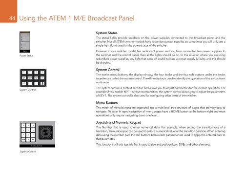
System Status<br />
DSK 1<br />
TIE<br />
DSK 2<br />
TIE<br />
The status lights provide feedback on the power supplies connected to the broadcast panel and the<br />
switcher. Not all <strong>ATEM</strong> switcher models have redundant power supplies so sometimes you will only see a<br />
single light illuminated for the power status of the switcher.<br />
Power Status<br />
However if your switcher model has redundant power and you have connected two power supplies to<br />
the switcher and the control panel, then all the lights should be on. In this situation where you are using<br />
redundant power supplies, any light that turns off could indicate a power supply is faulty, and this should<br />
be checked.<br />
DSK 1<br />
CUT<br />
DSK 1<br />
AUTO<br />
DSK 2<br />
CUT<br />
DSK 2<br />
AUTO<br />
KEY<br />
1<br />
FTB<br />
LUMA<br />
KEY<br />
MASK<br />
MENU<br />
KEY<br />
2<br />
CHROMA<br />
KEY<br />
System Control<br />
KEY<br />
3<br />
PATTRN<br />
KEY<br />
KEY<br />
4<br />
DVE<br />
HOME<br />
System Control<br />
1 2 3<br />
The twelve 4 menu 5 buttons, 6 the display window, the four knobs and the four soft buttons under the knobs<br />
together are called the system control. The 4 line display is used to identify the operation of the soft buttons<br />
7 8 9<br />
and knobs.<br />
CAM<br />
0 CLR<br />
The system control is context sensitive and allows you to adjust parameters for the current operation. For<br />
example if you enable KEY 1 in your next transition, the system control allows you to adjust the parameters<br />
of KEY 1. The system control is also used for configuring other parts of the switcher.<br />
CUT<br />
FILL<br />
Menu Buttons<br />
The matrix of menu buttons are organized into a multi level tree structure of pages that are very easy to<br />
navigate. To assist in rapid navigation all menu pages have a HOME button at the bottom right and most<br />
DSK 1 DSK 2<br />
operations only require TIE navigating TIE down one level.<br />
ON ON ON ON<br />
BKGD KEY 1 KEY 2 KEY 3 KEY 4<br />
1 2 3<br />
4 5 6<br />
7 8 9<br />
CAM 0 CLR<br />
SHIFT<br />
DIP<br />
MIX<br />
DVE<br />
WIPE<br />
Joystick and Numeric Keypad<br />
The Number Pad is used to enter numerical data. For example, when setting the transition rate of a<br />
transition, the number pad can be used to enter a numerical value for the transition duration. When entering<br />
DSK 1 DSK 2<br />
data using the number CUT pad, CUT the soft buttons below each parameter are used to apply the entered data to<br />
that parameter.<br />
PREV<br />
TRANS<br />
CUT<br />
AUTO<br />
The Joystick is a 3-axis DSK 1 joystick DSK 2 that FTB is used to size and position keys, DVEs and other elements.<br />
AUTO<br />
AUTO<br />
Joystick Control<br />
ON ON ON ON<br />
GD KEY 1 KEY 2 KEY 3 KEY 4<br />
DSK 1<br />
TIE<br />
DSK 2<br />
TIE<br />
IP<br />
IX<br />
DVE<br />
WIPE