Tree Configuration Thermosyphon Study - LEPTEN
Tree Configuration Thermosyphon Study - LEPTEN
Tree Configuration Thermosyphon Study - LEPTEN

Create successful ePaper yourself
Turn your PDF publications into a flip-book with our unique Google optimized e-Paper software.
Te<br />
−Tc<br />
Rt<br />
= (1)<br />
Q<br />
where T e and T c [K] are the evaporator and condenser average temperatures, respectively, and Q [W] is the<br />
thermosyphon rate of heat transfer.<br />
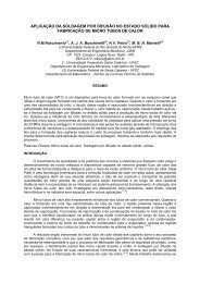
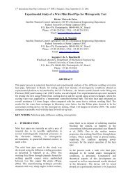
Condensers<br />
Evaporator<br />
Water feeding tube<br />
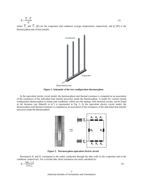
Figure 1. Schematic of the tree configuration thermosyphon<br />
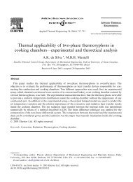
In the equivalent electric circuit model, the thermosyphon total thermal resistance is computed as an association<br />
of the resistances of the individual heat transfer processes inside the thermosyphon. A model for vertical normal<br />
configuration thermosyphon in steady state conditions, which uses the analogy with electrical circuits, can be found<br />
in the literature (see Mantelli et al. 2 ) is represented in Fig. 2. In the equivalent electric circuit model, the<br />
thermosyphon total thermal resistance is computed as an association of the resistances of the individual heat transfer<br />
processes inside the thermosyphon.<br />
Figure 2. <strong>Thermosyphon</strong> equivalent electric circuit<br />
Resistances R 1 and R 7 correspond to the radial conduction through the tube walls in the evaporator and in the<br />
condenser, respectively. For a circular tube, these resistances are easily calculated as:<br />
ln( re<br />
/ ri<br />
)<br />
R1 = 2π k l<br />
(2)<br />
t e<br />
3<br />
American Institute of Aeronautics and Astronautics