Tree Configuration Thermosyphon Study - LEPTEN
Tree Configuration Thermosyphon Study - LEPTEN
Tree Configuration Thermosyphon Study - LEPTEN

You also want an ePaper? Increase the reach of your titles
YUMPU automatically turns print PDFs into web optimized ePapers that Google loves.
low up, the rivulets are broken and liquid is spread all around the evaporator, wetting the entire internal wall and<br />
increasing the heat transfer coefficient (see Faghri 1 for more details).<br />
The R 3 and R 5 resistances shown in the equivalent circuit of Fig. 2 appear at the liquid-vapor interface in the<br />
evaporator and in the condenser, respectively. These resistances can generally be ignored (Brost 6 ). The resistance R 4<br />
is associated with the drop of saturation temperature of the vapor due to the pressure drop of the vapor flow between<br />
the evaporator and the condenser. In general, this resistance can also be neglected.<br />
Finally, the R 8 resistance is due to the axial heat conduction between the evaporator and the condenser through<br />
the tube walls. It can be estimated as the average length that the heat crosses between the evaporator and the<br />
condenser, which is the summation of half the length of the evaporator, half the length of the condenser and the<br />
length of the adiabatic section, divided by the thermal conductivity and by the cross-section area of the tube walls:<br />
( le<br />
+ lc<br />
) 2 + la<br />
R8<br />
=<br />
(9)<br />
2 2<br />
ktπ<br />
( re<br />
− ri<br />
)<br />
In general, the axial conduction resistance R 8 is much larger than the other resistances of the equivalent circuit of<br />
Fig. 2, and, as it is in parallel with resistances R 1 , R 2 , R 3 , R 4 , R 5 , R 6 and R 7 , which are associated in series, it can be<br />
neglected. As a result, the thermosyphon total thermal resistance is given by the summation in series of the<br />
resistances R 1 , R 2 , R 6 and R 7 . The thermophysical properties appearing in the above equations must be estimated at<br />
the average temperature of the thermosyphon, given by the arithmetic mean of the average temperatures of the<br />
evaporator and of the condenser.<br />
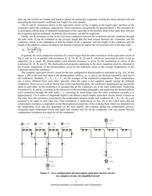
The complete equivalent electric circuit for the tree configuration thermosyphon is presented in Fig. 3(a). In this<br />
figure, q [W] is the total heat input to the thermosyphon, while q 1 ,q 2 , q 3 and q 4 are the heat rejected by each one of<br />
the condensers. Similarly, T c,1 , T c,2 , T c,3 , T c,4 are the averages of the condensers temperatures. These temperatures<br />
are, a priori, different from each other, specially when the vapor is not supplied equally among the different<br />
condensers. However, as it will be shown later in the experimental study, the condensers temperatures are practically<br />
equal to each other. In this modeling it is assumed that all the condensers are at the same temperature. Neglecting<br />
resistances R 3 , R 4 and R 5 , according to the discussion in the preceding paragraphs, and neglecting the thermal path by<br />
axial conduction through the tube walls, i. e., assuming R 8 much larger than the other resistances (actually it is<br />
approximately 3 to 4 orders of magnitude higher), one obtain a much simpler equivalent circuit, which is shown in<br />
Fig. 3(b). Also, the resistances associated to the condensation process inside each condenser (R 6,1 , R 6,2 , R 6,3 , R 6,4 ) are<br />
assumed to be equal to each other (R 6 ). This assumption is made based on Eqs. (4) to (6), which show that the<br />
condensation resistance is dependent on the thermophysical properties of the working fluid, which are dependent on<br />
the temperature level and also dependent on the heat transfer rate released during the condensation process.<br />
Assuming equal temperature levels and equal heat transfer rate for all the condensers, one can assume that the<br />
condensation resistances are equal for all the condensers.<br />
1<br />
2<br />
q = q + q + q + q<br />
1<br />
T [°C] T [°C] T [°C] T [°C]<br />
c,1 c,2 c,3 c,4<br />
2<br />
q [W] q [W] q [W] q [W]<br />
3<br />
3<br />
4<br />
4<br />
R R6,1<br />
R R<br />
7<br />
5,1 R7<br />
R6,2<br />
R 5,2<br />
R7<br />
R6,3<br />
R 5,3 R7<br />
R6,4<br />
R 5,4<br />
R7<br />
6<br />
R7<br />
R6<br />
R7<br />
R6<br />
R7<br />
R6<br />
q [W]<br />
T [°C]<br />
c<br />
R 4,1<br />
R 4,2<br />
R 4,3<br />
R 4,4<br />
R8,1<br />
R 8,2<br />
R R<br />
8,3<br />
8,4<br />
T [°C]<br />
v<br />
R 3<br />
R 2<br />
R 2<br />
R 1<br />
R 1<br />
T [°C]<br />
e<br />
T [°C]<br />
e<br />
q [W]<br />
(a)<br />
q [W]<br />
Figure 3. <strong>Tree</strong> configuration thermosyphon equivalent electric circuit:<br />
(a) complete circuit, (b) simplified circuit<br />
5<br />
American Institute of Aeronautics and Astronautics<br />
(b)