Tree Configuration Thermosyphon Study - LEPTEN
Tree Configuration Thermosyphon Study - LEPTEN
Tree Configuration Thermosyphon Study - LEPTEN

You also want an ePaper? Increase the reach of your titles
YUMPU automatically turns print PDFs into web optimized ePapers that Google loves.
Since the main objective of this work is to analyze the condensation process inside the parallel condensers and<br />
due to difficulties in assessing the evaporation resistance with the experimental set-up employed in this study<br />
(discussed later), this work will be focused on the condenser resistance only. The condenser resistance R c is<br />
computed as:<br />
Tv<br />
− Tc<br />
R 6 + R<br />
R<br />
7<br />
c = =<br />
(10)<br />
q 4<br />
where T v [°C] is the temperature of the vapor inside the thermosyphon.<br />
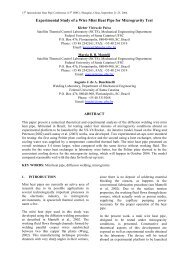
III. Experimental <strong>Study</strong><br />
The tree configuration thermosyphon tested consists of four vertical condensers with a common evaporator. All<br />
tubes and caps were made of 0.2% carbon steel (AISI 1020 or C22 Standards) and connected by welding. The<br />
condensers are made of 21 mm external diameter tubes with a length of 634 mm, and the evaporator is made of a 42<br />
mm external diameter tube with a length of 408 mm. The thickness of the tube walls are 1,5 mm and 2,65 mm for<br />
the condenser and the evaporator, respectively. These dimensions are similar to other thermosyphon configurations<br />
already tested in the laboratory (Mantelli et al. 2 ). The external surface of the thermosyphon tube was electrogalvanized.<br />
The thermosyphon was evacuated to approximately 10 -3 mbar. The selected working fluid was distilled<br />
water due to many reasons: water is cheap, easy to obtain and presents good thermal properties. The fluid was<br />
charged by means of a small tube welded in the evaporator section, as it can be observed in Fig. 2. Approximately<br />
300 ml of distilled water was used to fill the evaporator to up to 70% of its internal volume.<br />
Experimental Set-up<br />
The experimental set up consists of a frame, a cooling circuit, a thermally insulated electrical heater, a power<br />
supply unit, thermocouples, a data acquisition unit and a personal computer for data storage. Figure 4(a) shows a<br />
picture of the experimental setup. A semi-cylindrical electrical resistance is attached to the bottom of the evaporator<br />
tube. Its temperature distribution as a function of its length was measured before mounting with the heater in<br />
stagnant air and it was found to be not uniform, with a maximum difference of approximately 125 K between the<br />
center and the tips of the heater. To reduce the heat losses to the surrounding environment, the evaporator tube and<br />
the assembled heater were insulated with two layers of 35mm thick glass wool. A closed water-cooling circuit is<br />
mounted around the condenser tubes to remove the heat from the thermosyphon. It has one entry and one exit tube<br />
which allow the flow of the refrigeration water from a controlled thermal bath. The setup was instrumented by<br />
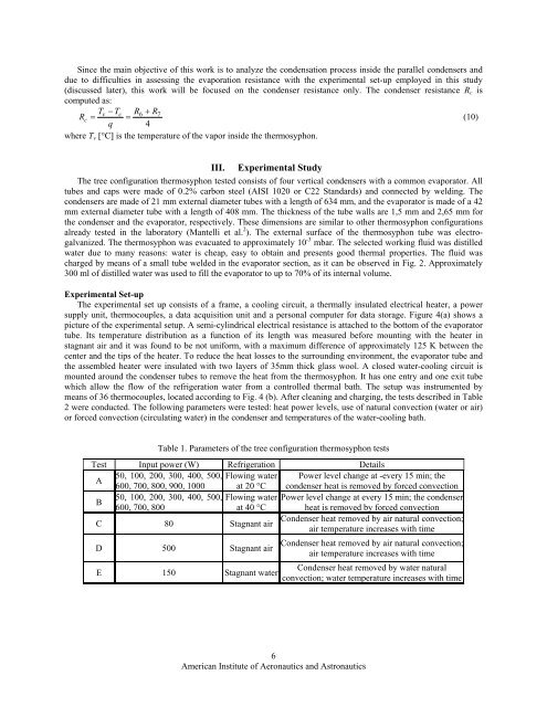
means of 36 thermocouples, located according to Fig. 4 (b). After cleaning and charging, the tests described in Table<br />
2 were conducted. The following parameters were tested: heat power levels, use of natural convection (water or air)<br />
or forced convection (circulating water) in the condenser and temperatures of the water-cooling bath.<br />
Table 1. Parameters of the tree configuration thermosyphon tests<br />
Test Input power (W) Refrigeration Details<br />
A<br />
50, 100, 200, 300, 400, 500, Flowing water Power level change at -every 15 min; the<br />
600, 700, 800, 900, 1000 at 20 °C condenser heat is removed by forced convection<br />
B<br />
50, 100, 200, 300, 400, 500, Flowing water Power level change at every 15 min; the condenser<br />
600, 700, 800<br />
at 40 °C heat is removed by forced convection<br />
C 80 Stagnant air<br />
Condenser heat removed by air natural convection;<br />
air temperature increases with time<br />
D 500 Stagnant air<br />
E 150 Stagnant water<br />
Condenser heat removed by air natural convection;<br />
air temperature increases with time<br />
Condenser heat removed by water natural<br />
convection; water temperature increases with time<br />
6<br />
American Institute of Aeronautics and Astronautics