Datasheet - PMCCatalogue
Datasheet - PMCCatalogue
Datasheet - PMCCatalogue

Create successful ePaper yourself
Turn your PDF publications into a flip-book with our unique Google optimized e-Paper software.
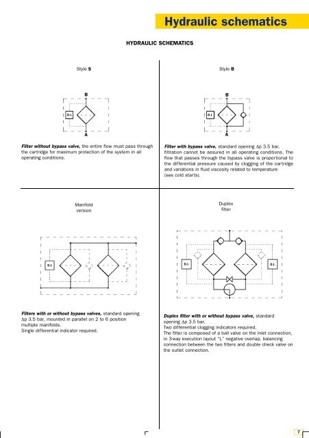
Hydraulic schematics<br />
HYDRAULIC SCHEMATICS<br />
Style S<br />
Style B<br />
B<br />
B<br />
D.I.<br />
D.I.<br />
A<br />
Filter without bypass valve, the entire flow must pass through<br />
the cartridge for maximum protection of the system in all<br />
operating conditions.<br />
A<br />
Filter with bypass valve, standard opening Δp 3.5 bar,<br />
filtration cannot be assured in all operating conditions. The<br />
flow that passes through the bypass valve is proportional to<br />
the differential pressure caused by clogging of the cartridge<br />
and variations in fluid viscosity related to temperature<br />
(see cold starts).<br />
Manifold<br />
version<br />
Duplex<br />
filter<br />
D.I. D.I. D.I.<br />
Filters with or without bypass valves, standard opening<br />
Δp 3.5 bar, mounted in parallel on 2 to 6 position<br />
multiple manifolds.<br />
Single differential indicator required.<br />
Duplex filter with or without bypass valve, standard<br />
opening Δp 3.5 bar.<br />
Two differential clogging indicators required.<br />
The filter is composed of a ball valve on the inlet connection,<br />
in 3-way execution layout “L” negative overlap, balancing<br />
connection between the two filters and double check valve on<br />
the outlet connection.<br />
7