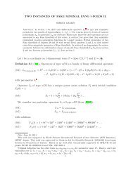
STUDY SUMMARY - IPMU
STUDY SUMMARY - IPMU
STUDY SUMMARY - IPMU

You also want an ePaper? Increase the reach of your titles
YUMPU automatically turns print PDFs into web optimized ePapers that Google loves.
<strong>SUMMARY</strong> REPORT<br />
WIDE FIELD FIBER-FED OPTICAL<br />
MULTI-OBJECT SPECTROMETER (WFMOS)<br />
There are four Metrology cameras, mounted on the prime focus support struts looking down<br />
at back-illuminated fiber tips via the primary mirror of Subaru. The metrology cameras determine<br />
the location of the fiber tips, allowing accurate positioning of the fibers on the selected science<br />
targets. Each metrology camera consists of imaging optics with a CCD detector and includes<br />
an internal flat-field source. Calibration of geometrical distortion inherent in the optics of<br />
the metrology cameras is achieved by having 154 illuminated fixed Fiducial Fibers whose positions<br />
are known accurately. Of the fixed fiducials, 91 are within the bounds of the hexagonal<br />
field of view, while 48 fixed fiducial fibers are at the perimeter of the hexagonal field. Beyond<br />
the perimeter of the hexagonal field, 15 fiducials are used to provide encoding of the rotator angle.<br />
The fiducial fibers also allow correction for geometric distortion in the WFC, through measurement<br />
and modeling.<br />
The field of view of each Metrology camera is designed to image 1/4 of the optics bench fibers.<br />
The cameras image the backlit science fibers by viewing the optics bench through the telescope<br />
optical system, including the WFC and the primary mirror. The centroid of each fiber image<br />
is calculated and used to determine each science fiber position with respect to the fixed-fiber<br />
locations. This coordinate system is accurately referenced to the A&G camera, allowing accurate<br />
placement of astronomical targets on the science fibers.<br />
The science fibers are back-illuminated by sources located inside the three spectrographs.<br />
Only one set of 800 fibers is illuminated at a time, in a manner allowing no ambiguity in determining<br />
fiber positions in the case that two fibers occupy a region of overlapping patrol regions.<br />
The Prime Focus Instrument (PFI) consists of the Optical Bench, which contains the Field<br />
Element, Fiber Positioner System, Acquisition and Guide System, and components of the Fiber<br />
System Power Distribution System and Thermal System. The optical bench is mounted to the<br />
Rotator within the PFI via a bi-conic structure. This structure is tuned in stiffness to compensate<br />
for differential flexure between the WFC and the Rotator interface where the WFMOS components<br />
are mounted. The PFI is housed within the PFU, which can be installed and removed from<br />
the telescope as a single unit.<br />
The Power Distribution System is located within the PFU to provide power conditioning<br />
and control to the electronics associated with the Fiber Positioner System, the Acquisition and<br />
Guide System, and the Metrology System. The distribution system interfaces to the telescope<br />
facility power and receives power control inputs from the System Control function. The Thermal<br />
System provides the interface between the telescope facility cooling system and the instrument<br />
systems located in the PFU to prevent excess heat from disturbing the telescope’s viewing<br />
environment.<br />
The Spectral Calibration Lamps provide the capability to measure the spectral response of<br />
the WFMOS instrument by providing a spectral source at the input to the telescope. The calibration<br />
lamps will be mounted on the telescope apart from the Prime Focus Unit.<br />
The System Control provides the capability to manage an observation’s preparation and<br />
execution. Preparation tasks include parsing large surveys into a series of individual observations,<br />
matching fibers to designated targets and selecting appropriate guide stars, predicting exposure<br />
times, and describing observations in a Subaru-format file. During telescope observations,<br />
the System Control orchestrates the instrument systems to achieve successful data collection, sequences<br />
the Metrology and Fiber Positioner Systems to achieve target acquisition with the fibers,<br />
interfaces to the Subaru Observatory Software System, and provides operator interfaces for<br />
quick-look data and instrument health and safety displays. The System Control also provides the<br />
21