STUDY SUMMARY - IPMU
STUDY SUMMARY - IPMU
STUDY SUMMARY - IPMU

Create successful ePaper yourself
Turn your PDF publications into a flip-book with our unique Google optimized e-Paper software.
<strong>SUMMARY</strong> REPORT<br />
WIDE FIELD FIBER-FED OPTICAL<br />
MULTI-OBJECT SPECTROMETER (WFMOS)<br />
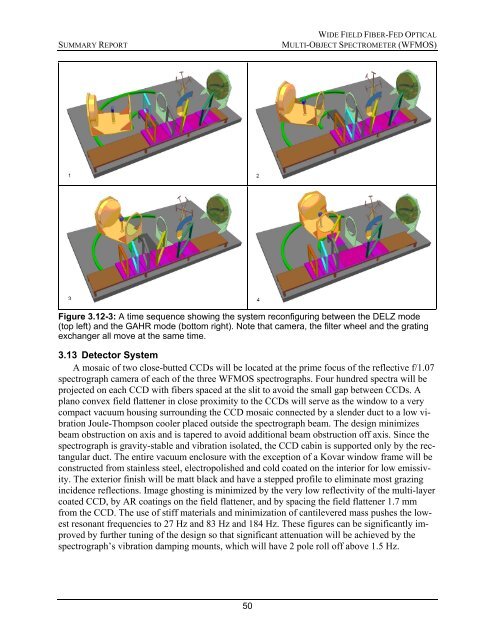
Figure 3.12-3: A time sequence showing the system reconfiguring between the DELZ mode<br />
(top left) and the GAHR mode (bottom right). Note that camera, the filter wheel and the grating<br />
exchanger all move at the same time.<br />
3.13 Detector System<br />
A mosaic of two close-butted CCDs will be located at the prime focus of the reflective f/1.07<br />
spectrograph camera of each of the three WFMOS spectrographs. Four hundred spectra will be<br />
projected on each CCD with fibers spaced at the slit to avoid the small gap between CCDs. A<br />
plano convex field flattener in close proximity to the CCDs will serve as the window to a very<br />
compact vacuum housing surrounding the CCD mosaic connected by a slender duct to a low vibration<br />
Joule-Thompson cooler placed outside the spectrograph beam. The design minimizes<br />
beam obstruction on axis and is tapered to avoid additional beam obstruction off axis. Since the<br />
spectrograph is gravity-stable and vibration isolated, the CCD cabin is supported only by the rectangular<br />
duct. The entire vacuum enclosure with the exception of a Kovar window frame will be<br />
constructed from stainless steel, electropolished and cold coated on the interior for low emissivity.<br />
The exterior finish will be matt black and have a stepped profile to eliminate most grazing<br />
incidence reflections. Image ghosting is minimized by the very low reflectivity of the multi-layer<br />
coated CCD, by AR coatings on the field flattener, and by spacing the field flattener 1.7 mm<br />
from the CCD. The use of stiff materials and minimization of cantilevered mass pushes the lowest<br />
resonant frequencies to 27 Hz and 83 Hz and 184 Hz. These figures can be significantly improved<br />
by further tuning of the design so that significant attenuation will be achieved by the<br />
spectrograph’s vibration damping mounts, which will have 2 pole roll off above 1.5 Hz.<br />
50