Download Prodigy Instruction Manual PDF file - Raynor Garage Doors
Download Prodigy Instruction Manual PDF file - Raynor Garage Doors
Download Prodigy Instruction Manual PDF file - Raynor Garage Doors

You also want an ePaper? Increase the reach of your titles
YUMPU automatically turns print PDFs into web optimized ePapers that Google loves.
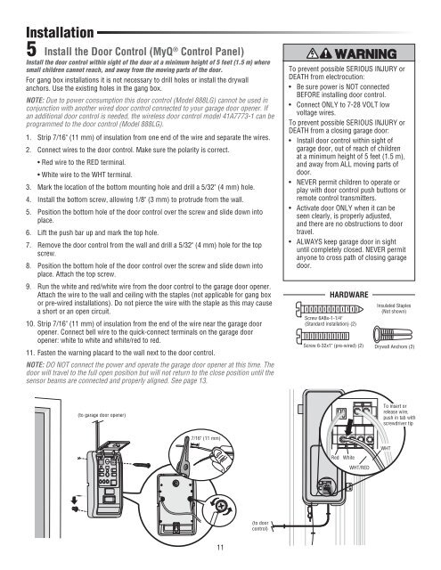
Installation<br />
5<br />
Install the Door Control (MyQ ® Control Panel)<br />
Install the door control within sight of the door at a minimum height of 5 feet (1.5 m) where<br />
small children cannot reach, and away from the moving parts of the door.<br />
For gang box installations it is not necessary to drill holes or install the drywall<br />
anchors. Use the existing holes in the gang box.<br />
NOTE: Due to power consumption this door control (Model 888LG) cannot be used in<br />
conjunction with another wired door control connected to your garage door opener. If<br />
an additional door control is needed, the wireless door control model 41A7773-1 can be<br />
programmed to the door control (Model 888LG).<br />
1. Strip 7/16" (11 mm) of insulation from one end of the wire and separate the wires.<br />
2. Connect wires to the door control. Make sure the polarity is correct.<br />
• Red wire to the RED terminal.<br />
• White wire to the WHT terminal.<br />
3. Mark the location of the bottom mounting hole and drill a 5/32" (4 mm) hole.<br />
4. Install the bottom screw, allowing 1/8" (3 mm) to protrude from the wall.<br />
5. Position the bottom hole of the door control over the screw and slide down into<br />
place.<br />
6. Lift the push bar up and mark the top hole.<br />
7. Remove the door control from the wall and drill a 5/32" (4 mm) hole for the top<br />
screw.<br />
8. Position the bottom hole of the door control over the screw and slide down into<br />
place. Attach the top screw.<br />
9. Run the white and red/white wire from the door control to the garage door opener.<br />
Attach the wire to the wall and ceiling with the staples (not applicable for gang box<br />
or pre-wired installations). Do not pierce the wire with the staple as this may cause<br />
a short or an open circuit.<br />
10. Strip 7/16" (11 mm) of insulation from the end of the wire near the garage door<br />
opener. Connect bell wire to the quick-connect terminals on the garage door<br />
opener: white to white and white/red to red.<br />
11. Fasten the warning placard to the wall next to the door control.<br />
NOTE: DO NOT connect the power and operate the garage door opener at this time. The<br />
door will travel to the full open position but will not return to the close position until the<br />
sensor beams are connected and properly aligned. See page 13.<br />
To prevent possible SERIOUS INJURY or<br />
DEATH from electrocution:<br />
• Be sure power is NOT connected<br />
BEFORE installing door control.<br />
• Connect ONLY to 7-28 VOLT low<br />
voltage wires.<br />
To prevent possible SERIOUS INJURY or<br />
DEATH from a closing garage door:<br />
• Install door control within sight of<br />
garage door, out of reach of children<br />
at a minimum height of 5 feet (1.5 m),<br />
and away from ALL moving parts of<br />
door.<br />
• NEVER permit children to operate or<br />
play with door control push buttons or<br />
remote control transmitters.<br />
• Activate door ONLY when it can be<br />
seen clearly, is properly adjusted,<br />
and there are no obstructions to door<br />
travel.<br />
• ALWAYS keep garage door in sight<br />
until completely closed. NEVER permit<br />
anyone to cross path of closing garage<br />
door.<br />
HARDWARE<br />
Screw 6ABx-1-1/4"<br />
(Standard installation) (2)<br />
Insulated Staples<br />
(Not shown)<br />
Screw 6-32x1" (pre-wired) (2) Drywall Anchors (2)<br />
(to garage door opener)<br />
To insert or<br />
release wire,<br />
push in tab with<br />
screwdriver tip<br />
7/16" (11 mm)<br />
Red<br />
White<br />
WHT/RED<br />
WHT<br />
(to door<br />
control)<br />
11