

1735 Operators Manual - Novatech Controls
1735 Operators Manual - Novatech Controls
1735 Operators Manual - Novatech Controls

You also want an ePaper? Increase the reach of your titles
YUMPU automatically turns print PDFs into web optimized ePapers that Google loves.
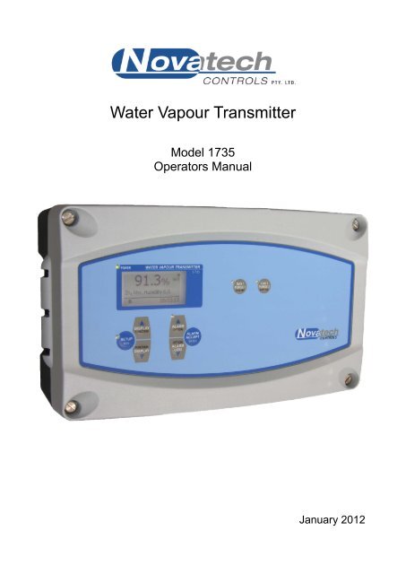
Water Vapour Transmitter<br />
Model <strong>1735</strong><br />
<strong>Operators</strong> <strong>Manual</strong><br />
January 2012
TABLE OF CONTENTS<br />
1. USING THIS MANUAL.................................................................................................................................. 5<br />
1.1 CAUTIONS .................................................................................................................................................. 5<br />
1.2 HEATER WARNING ...................................................................................................................................... 6<br />
2. INTRODUCTION ........................................................................................................................................... 7<br />
3. SPECIFICATIONS ......................................................................................................................................... 9<br />
3.1 HARDWARE SPECIFICATIONS ....................................................................................................................... 9<br />
3.2 OPERATIONAL SPECIFICATIONS ................................................................................................................. 10<br />
3.3 HEATER INTERLOCK RELAYS ..................................................................................................................... 11<br />
4. DISPLAY AND KEYPAD ............................................................................................................................ 13<br />
4.1 DISPLAY ................................................................................................................................................... 13<br />
4.2 TOP LINE DISPLAY .................................................................................................................................... 14<br />
4.3 KEYPAD ................................................................................................................................................... 15<br />
4.3.1 Keypad in RUN Mode ...................................................................................................................... 15<br />
4.3.2 Keypad in SETUP Mode ................................................................................................................. 16<br />
4.3.3 Information Screen .......................................................................................................................... 16<br />
5. SETUP MODE ............................................................................................................................................. 17<br />
5.1 SETUP MODE FUNCTION SUMMARY ......................................................................................................... 17<br />
5.2 SETUP MODE DETAILS ............................................................................................................................ 17<br />
5.2.0 To Change an Option in the SETUP Menu ..................................................................................... 17<br />
5.2.1 Probe 1 Offset ................................................................................................................................. 18<br />
5.2.2 Lower Line Items ............................................................................................................................. 18<br />
5.2.4 Oxygen Damping ............................................................................................................................. 19<br />
5.2.5 Spike Suppression .......................................................................................................................... 19<br />
5.2.6 Spike Trip Level ............................................................................................................................... 20<br />
6. ALARMS ..................................................................................................................................................... 21<br />
6.1 CHECKING AND ACCEPTING AN ALARM....................................................................................................... 21<br />
6.1.1 Current Alarms ................................................................................................................................ 22<br />
6.1.2 Alarm Log ........................................................................................................................................ 22<br />
6.2 ALARM RELAYS ........................................................................................................................................ 22<br />
6.3 COMMON ALARMS .................................................................................................................................... 23<br />
6.4 SELECTABLE PROCESS ALARMS ................................................................................................................ 24<br />
6.5 WARNING MESSAGES ............................................................................................................................... 24<br />
7. GAS CALIBRATE AND PURGE ................................................................................................................ 25<br />
7.1 ACTIONS THAT OCCUR WHEN THE GAS SOLENOID KEYS ARE PRESSED ....................................................... 26<br />
8. UPDATING THE SOFTWARE .................................................................................................................... 27<br />
9. INDEX .......................................................................................................................................................... 29<br />
January 2012<br />
<strong>1735</strong> Water Vapour Transmitter 3
© Copyright NOVATECH CONTROLS PTY LTD — 2012<br />
Edition - January 2012<br />
This manual describes the transmitter firmware version 1.20, January 2012<br />
Neither the whole nor any part of the information contained in, or the product described in, this manual may<br />
be adapted or reproduced in any material form except with the prior written approval of <strong>Novatech</strong> <strong>Controls</strong><br />
Pty Ltd (<strong>Novatech</strong>).<br />
The product described in this manual and products for use with it, are subject to continuous developments<br />
and improvement. All information of a technical nature and particulars of the product and its use (including<br />
the information in this manual) are given by <strong>Novatech</strong> in good faith. However, it is acknowledged that there<br />
may be errors or omissions in this manual. A list of details of any amendments or revisions to this manual<br />
can be obtained upon request from <strong>Novatech</strong> <strong>Controls</strong> Technical Enquiries. <strong>Novatech</strong> <strong>Controls</strong> welcome<br />
comments and suggestions relating to the product and this manual.<br />
All correspondence should be addressed to: -<br />
Technical Enquiries<br />
<strong>Novatech</strong> <strong>Controls</strong> Pty Ltd<br />
309 Reserve Road, Tel: +61 3 9585 2833<br />
Cheltenham Fax: +61 3 9585 2844<br />
Victoria 3192<br />
Email: info@novatech.com.au<br />
Australia<br />
Web site: http://www.novatech.com.au/<br />
<strong>Novatech</strong> <strong>Controls</strong> or their authorised dealers should carry out all maintenance and service on the product.<br />
<strong>Novatech</strong> <strong>Controls</strong> can accept no liability whatsoever for any loss or damage caused by service or<br />
maintenance by unauthorised personnel. This manual is intended only to assist the reader in the use of the<br />
product, and therefore <strong>Novatech</strong> <strong>Controls</strong> shall not be liable for any loss or damage whatsoever arising from<br />
the use of any information or particulars in, or any error or omission in, this manual, or any incorrect use of<br />
the product.<br />
January 2012<br />
4 <strong>1735</strong> Water Vapour Transmitter
1. USING THIS MANUAL<br />
This manual is intended to be used by the operator. It is not intended to describe how the <strong>1735</strong> water<br />
vapour transmitter should be connected, configured or serviced. If more detailed information is required than<br />
is shown in this manual the <strong>1735</strong> Technical <strong>Manual</strong> should be used. This is supplied with each transmitter<br />
and is also available on the <strong>Novatech</strong> web site at www.novatech.com.au<br />
It is assumed in this manual that the transmitter has been installed by competent personal and that the wiring<br />
to the main power supply, the oxygen probe and all the associated signal devices complies with the local<br />
safety codes and regulations.<br />
1.1 Cautions<br />
Please read the safety information below before connecting power to the transmitter.<br />
CAUTION 1<br />
The probe heater is supplied with mains voltage. This supply has electrical shock danger to maintenance<br />
personnel. Always isolate the transmitter before working with the probe.<br />
The EARTH wire (green) from a heated probe must ALWAYS be connected to earth.<br />
CAUTION 2<br />
Combustion or atmosphere control systems can be dangerous. Burners must be mechanically set up so that<br />
in the worst case of equipment failure, the system cannot generate explosive atmospheres. This danger is<br />
normally avoided with flue gas trim systems by adjustment so that in the case of failure the appliance will not<br />
generate CO in excess of 400 ppm in the flue. The CO level in the flue should be measured with a separate<br />
CO instrument, normally an infrared or fuel cell type.<br />
CAUTION 3<br />
The oxygen probe is heated to over 700°C (1300°F) and is a source of ignition. Since raw fuel leaks can<br />
occur during burner shutdown, the transmitter has an interlocking relay that removes power from the probe<br />
heater when the main fuel shut-off valve power is off. If this configuration does not suit or if it is possible for<br />
raw fuel to come into contact with a hot oxygen probe then the Model <strong>1735</strong> transmitter with a heated probe<br />
will not be safe in your application.<br />
An unheated probe can be utilised in such applications, however the oxygen readings are valid only above<br />
650°C (1200°F).<br />
CAUTION 4<br />
FIL-3 filter. If the optional FIL-3 has been fitted to the 1231 probe in this installation, please read the<br />
Important Notice in the Technical <strong>Manual</strong>.<br />
CAUTION 5<br />
The heater is supplied from the mains power directly, and the temperature is controlled at 720°C (1330°F).<br />
The outside of the process end of the probe can get to temperatures that are dangerous to touch. Wear<br />
insulating gloves when handling a probe that has been on.<br />
January 2012<br />
<strong>1735</strong> Water Vapour Transmitter 5
1.2 Heater Warning<br />
The probe heater is supplied with mains voltage. This supply has electrical shock danger to maintenance<br />
personnel. Always isolate the transmitter before working with the probe.<br />
The EARTH wire (green) from the probe must always be connected to earth.<br />
The heater is supplied from the mains power directly, and the temperature is controlled at 720°C (1328°F).<br />
The outside of the process end of the probe can get to temperatures that are dangerous to touch. Wear<br />
insulating gloves when handling a probe that has been on.<br />
January 2012<br />
6 <strong>1735</strong> Water Vapour Transmitter
2. INTRODUCTION<br />
The <strong>Novatech</strong> <strong>1735</strong> water vapour transmitter is designed for measuring water vapour in drying and baking<br />
applications, where the drying temperature is above the maximum limit of conventional relative humidity<br />
sensors (which are limited to 130-150°C) or a more robust sensor is preferred. The transmitter signal can be<br />
used with a conventional controller to improve the efficiency of industrial drying or baking applications, as<br />
well as to optimise the quality of the product being dried or baked.<br />
There are seven basic types of installation for the <strong>1735</strong> transmitter (see table below)<br />
Mode Selection mode in 1231 oxygen Second probe RGS temp.<br />
No. commissioning menu #4 probe installed installed sensor<br />
1 Indirect Fired, 1 zone Yes No No<br />
2 Indirect Fired, 2 zones Yes 1231 No<br />
3 Direct fired, fixed combustion Yes No No<br />
4 Direct fired, probes + RGS-01 + Temp. Yes RGS-01 Yes<br />
sensor<br />
5 Directly fired, external dry oxygen sensor Yes No No<br />
1. Indirectly heated dryers and ovens, 1 zone<br />
The in-situ 1231 probe measures the oxygen content within the drying chamber and calculations are<br />
performed to determine how much of the air space is taken up by water vapour. For indirectly heated dryers<br />
or ovens, an oxygen probe and transmitter are all that is required. The oxygen probe uses ambient air as a<br />
reference gas.<br />
2. Indirectly heated dryers and ovens, 2 zones<br />
If the dryer or oven has two zones that you would like to measure the humidity level in, a <strong>1735</strong> transmitter<br />
can be configured to read both zones and independently display and transmit the water vapour for each<br />
zone on independent channels.<br />
3. Directly heated dryers and ovens with constant combustion<br />
If the dryer or oven has a fixed combustion system (fixed firing rate), where the reduction of oxygen due to<br />
combustion is constant, then a reference gas sensor may not be necessary to condition reference gas from<br />
within the dryer. The dryer or oven oxygen level can be entered on the transmitter keyboard. The percent<br />
water vapour can be measured by gravimetric methods to calculate the correct initial setting.<br />
4. Directly heated dryers and ovens using separate oxygen sensors for the wet and dry<br />
measurements<br />
Where dryers or ovens use direct fired combustion, and the combustion oxygen can vary, 2 oxygen sensors<br />
can be used. This mode is different to the last mode in that it uses a 1231 probe to read the wet gas oxygen<br />
level in the dryer and the RGS-01 oxygen sensor to read the dry gas. The dry measurement of oxygen in the<br />
dryer or oven is measured after removing most of the water vapour. A temperature sensor is used to<br />
measure the temperature of the gas as it enters the RGS-01 oxygen sensor to compensate for the moisture<br />
that is left in the gas stream.<br />
5. Directly heated dryers and ovens using an external dry gas oxygen measurement fed into<br />
the <strong>1735</strong> as a 4-20mA signal<br />
Where dryers or ovens use direct fired combustion, and the combustion oxygen can vary, 2 oxygen sensors<br />
can be used. This mode is different to the last two modes in that it uses a 1231 probe to read the wet gas<br />
oxygen level in the dryer and a third party oxygen sensor to read the dry gas. It still uses an oxygen sensor<br />
but the oxygen measurement is fed into the <strong>1735</strong> as a 4-20mA signal proportional to 0-25% oxygen. The dry<br />
measurement of oxygen in the dryer or oven is measured after removing most of the water vapour. A<br />
temperature sensor is still used to measure the temperature of the gas as it enters the dry gas oxygen<br />
sensor to compensate for the moisture that is left in the gas stream.<br />
January 2012<br />
<strong>1735</strong> Water Vapour Transmitter 7
The <strong>1735</strong> water vapour transmitter has a variety of user-selectable functions. They are simple to use<br />
because each selection is menu driven. For options you are not sure about, read the manual on that<br />
particular item in chapter 5, SETUP mode.<br />
Features include:-<br />
Inputs<br />
Two zirconia oxygen probe, heated or unheated<br />
Furnace, kiln or flue thermocouple, field selectable as type K or J<br />
Reference gas sensor (RGS) temperature. Solid state sensor.<br />
Main flame established safety interlock (for heated probes only)<br />
Purge flow switch<br />
Outputs<br />
Two linearised 4-20mA or 0-20mA DC isolated outputs, max. load 1000Ω, 12 bit resolution<br />
The output function and the range are field selectable<br />
Common alarm relay (programmable)<br />
Three other alarm relays with selectable functions<br />
Computer<br />
The RS 232-C or RS 485 terminals for connection of a computer terminal or printer for diagnostics of the<br />
transmitter, probe or drying process. This connection is suitable for network connection to a computer, DCS<br />
or PLC using MODBUS protocol.<br />
Display<br />
Multi font graphical display<br />
Large characters for the top line<br />
Selectable top line function<br />
Water vapour range from 0 to 100%<br />
Dew point from -50°C to 100°C (-58°F to 212°F)<br />
Absolute humidity from 0 to 10,000 g/kg water vapour/dry process gas<br />
Mass fraction 0 to 1000 g/kg water vapour/process gas<br />
Oxygen from 1x 10 -30 to 100%<br />
Multiple lower line items for the secondary functions. eg Probe temperature, Dew point probe #2<br />
Alarm display mode that shows the time the alarm occurred, acceptance time and the cleared time<br />
Alarm log mode that keeps the time the alarm occurred, the acceptance time and the time the alarm was<br />
cleared for the last 4,000 alarms<br />
Power<br />
Universal mains supply voltage, 100 to 240VAC<br />
Automatically detects the mains voltage and frequency and set the power control accordingly<br />
January 2012<br />
8 <strong>1735</strong> Water Vapour Transmitter
3. SPECIFICATIONS<br />
3.1 Hardware Specifications<br />
Number of oxygen probes: 1 or 2<br />
Water vapour range: 0 to 100%<br />
Dew point range: -50 to 100°C<br />
Absolute humidity range:<br />
Mass fraction range:<br />
0 to 10,000 g/kg<br />
0 to 1,000 g/kg<br />
Dryer RH range: 0.0 to 100%<br />
Oxygen range: 1 x 10 -30 to 100%<br />
Oxygen accuracy:<br />
Thermocouple types:<br />
±1% of actual measured oxygen value with a repeatability of ±0.5% of the<br />
measured value<br />
Type K and J<br />
Temperature accuracy: +/- 2°C<br />
Analog outputs:<br />
Output load:<br />
0-20mA or 4-20mA field selectable<br />
Active outputs (Do NOT loop power these outputs)<br />
1000 ohm max<br />
Alarm relays: 4<br />
Alarm relay contacts:<br />
Mains voltage supply:<br />
Power:<br />
2Amp 240VAC, 2A 30VDC<br />
(WARNING: Do not use both mains voltage and low voltage connections to<br />
adjacent alarm contacts)<br />
100 to 240VAC 50/60 Hz<br />
5 Watts for controller plus probe power<br />
500W max., 25% duty cycle each probe on 240VAC<br />
100W max., 100% duty cycle each probe on 110VAC<br />
~50W average on 110 and 240VAC after the probe has reached the operating<br />
temperature<br />
Environmental Rating: Operating Temperature -25°C to 55°C<br />
Relative Humidity 5% to 95% (non-condensing)<br />
Degree of Protection:<br />
Case Size:<br />
Case Weight:<br />
IP65<br />
IP54 with internal reference air pump<br />
260mm (10.2”) wide, 160mm (6.3”) high, 90mm (3.5”) deep<br />
3 Kg (6.6 lbs.)<br />
January 2012<br />
<strong>1735</strong> Water Vapour Transmitter 9
3.2 Operational Specifications<br />
Range of outputs on channel #1:<br />
Field selectable from the following:<br />
Function Minimum Range Maximum Range<br />
Water vapour 1 20% 0 to 100%<br />
Dew point 1 20°C -50 to 100°C<br />
Absolute humidity 1 200g/Kg 0 to 10,000 g/kg<br />
Mass fraction 1 50g/Kg 0 to 1,000 g/kg<br />
Probe 1 oxygen 1.0% 0.0 to 25.0%<br />
Probe 2 oxygen 1.0% 0.0 to 25.0%<br />
No output<br />
Range of outputs on channel #2:<br />
Field selectable from the following:<br />
Function Minimum Range Maximum Range<br />
Water vapour 2 20% 0 to 100%<br />
Dew point 2 20°C -50 to 100°C<br />
Absolute humidity 2 200g/Kg 0 to 10,000 g/Kg<br />
Mass fraction 2 50g/Kg 0 to 1,000g/kg<br />
Probe 1 oxygen 1.0% 0.0 to 25.0%<br />
Probe 2 oxygen 1.0% 0.0 to 25.0%<br />
No output<br />
Range of local oxygen indication: 1.0 x 10 -30 to 100%<br />
Local display, secondary functions:<br />
Zone 2 water vapour 0 to 100%<br />
Zone 1 dew point -50 to 100°C<br />
Zone 2 dew point -50 to 100°C<br />
Zone 1 absolute humidity<br />
0 to 1,000 kg/Kg<br />
Zone 2 absolute humidity<br />
0 to 1,000 kg/kg<br />
Zone 1 mass fraction<br />
0 to 1,000 g/kg<br />
Zone 2 mass fraction<br />
0 to 1,000 g/kg<br />
Ambient temperature -25 to 80°C<br />
Ambient relative humidity 5 to 95%<br />
Runtime<br />
>10 years (hours and minutes)<br />
Service date<br />
Day/Month/Year<br />
Probe 1 temperature -25 to 1372°C<br />
Probe 2 temperature -25 to 1372°C<br />
Probe 1 EMF<br />
-40 to 1350mV<br />
Probe 2 EMF<br />
-40 to 1350mV<br />
Probe 1 impedance<br />
0.0 to 300.0kohm<br />
Probe 2 impedance<br />
0.0 to 300.0kohm<br />
Probe 1 oxygen 1x10 -30 % to 100%<br />
Probe 2 oxygen 1x10 -30 % to 100%<br />
The top line item can also appear on the secondary line if another item is selected on the top line. This list is<br />
based on zone water vapour being selected for the top line.<br />
January 2012<br />
10 <strong>1735</strong> Water Vapour Transmitter
3.3 Heater Interlock Relays<br />
CAUTION<br />
Explosion protection when using heated probes is achieved by switching the power to the probe heater off<br />
whenever the main fuel valve is closed.<br />
The principle of safety is that if the main fuel valve is open then main flame has been established. With this<br />
primary source of ignition on, the probe heater can be safely switched on. The most dangerous situation is if<br />
fuel leaks into the combustion appliance when the fuel valve is closed. When power is removed from the<br />
main fuel valve the heater should also be switched off.<br />
To achieve this protection, connect a main fuel valve voltage free contact to the ‘BURNER ON SWITCH’<br />
terminals 10 & 11. When the main fuel valve is open, the voltage free contact should be closed. For<br />
installations where there is no risk of explosion, connect a link between terminals number 10 & 11.<br />
Heater Supply Interlock Connection for Heated Probes<br />
For safety, contacts must be<br />
open if the main fuel valve is<br />
closed in a direct fired system<br />
10<br />
BURNER INPUT<br />
11<br />
If a safety interlock is not required, a wire must be connected between terminals 10 &11 to enable –<br />
• The heaters on heated probes<br />
• Process alarms<br />
• Auto-purge and auto-cal checking.<br />
January 2012<br />
<strong>1735</strong> Water Vapour Transmitter 11
This page has been intentionally left blank.<br />
January 2012<br />
12 <strong>1735</strong> Water Vapour Transmitter
4. DISPLAY AND KEYPAD<br />
The <strong>1735</strong> transmitter has a graphic display, 8 keys that are accessed from the outside of the cabinet and 5<br />
LED indicators to show the status of the transmitter.<br />
All the keys have a dual function. The larger white text on the key is the function while the transmitter is in<br />
the RUN mode and the smaller black text on the key is the function in the SETUP mode.<br />
The SETUP mode is accessed by pressing the SETUP key. The transmitter will return to the RUN mode<br />
when the SETUP key is pressed again or one minute after the last key is pressed.<br />
4.1 Display<br />
The front panel of the model <strong>1735</strong> water vapour transmitter<br />
The <strong>1735</strong> display is used to show the top line item in a large font and the secondary functions in a smaller<br />
font. The default display is shown below with probe zone 1 water vapour on the top line and zone 2 water<br />
vapour on the lower line.<br />
Power on<br />
indicator<br />
Activity indicator<br />
(see below for<br />
details)<br />
POWER<br />
25.2%<br />
Z 2 Water Vapour 3.7%<br />
B<br />
WATER VAPOUR TRANSMITTER<br />
<strong>1735</strong><br />
WV<br />
14:20:36<br />
Heartbeat<br />
indicator<br />
Prime measurement indicator<br />
(WV, DP, O 2 , AH, MF, RH)<br />
Prime humidity measurement.<br />
User selectable<br />
Lower line,<br />
secondary measurements<br />
Current time<br />
In addition to displaying the current humidity level and the various secondary values, the display is also used<br />
to show the current and active alarm conditions and to configure the transmitter. This is achieved by<br />
entering the SETUP mode (see chapter 5).<br />
The Activity indicators show actions that are happening in the background.<br />
B The burner input has been enabled (terminals 10&11)<br />
A The transmitter is doing an auto calibration. This happens every minute or when the AUTO CAL key<br />
is pressed in setup mode<br />
T (Flashing) The probe(s) is(are) below operating temperature (650°C, 1200°F)<br />
Z The transmitter is doing an impedance check of the probe(s).<br />
January 2012<br />
<strong>1735</strong> Water Vapour Transmitter 13
4.2 Top Line Display<br />
The top line of the display shows the prime humidity measurement in a large font. The units are selectable<br />
from the following zone 1 items:<br />
Water vapour (WV)<br />
Dew point (DP)<br />
Probe oxygen (O 2 )<br />
Absolute humidity (AH)<br />
Mass fraction (MF)<br />
Whichever item is selected to be shown on the top line will not be shown on the lower line.<br />
The alarm levels will be based on whichever is selected as the top line units. See chapter 5.2.6 and 5.2.7.<br />
The selection is made in the commissioning menu. For access to this menu see the <strong>1735</strong> Technical manual.<br />
January 2012<br />
14 <strong>1735</strong> Water Vapour Transmitter
4.3 Keypad<br />
There are 8 keys built into the decal on the outside of the door of the <strong>1735</strong> transmitter. The key function is<br />
printed in WHITE and BLACK to identify the function of the key in either RUN mode or SETUP mode.<br />
Key text RUN mode (WHITE text) SETUP mode (BLUE/BLACK text)<br />
SETUP / RUN Enter SETUP mode Return to RUN mode<br />
DISPLAY / FUNCTION ∆ Display scroll up Function scroll up<br />
DISPLAY / FUNCTION ∇ Display scroll down Function scroll down<br />
ALARM / OPTION ∆ Alarm scroll up Option scroll up<br />
ALARM / OPTION ∇ Alarm scroll down Option scroll down<br />
ALARM ACCEPT / ENTER Alarm accept Enter<br />
GAS 1 PURGE 1 / SENS IMP Gas 1 / Purge 1 manual activate Probe impedance<br />
GAS 2 PURGE 2 / AUTO CAL Gas 2 / Purge 2 manual activate Auto calibrate<br />
4.3.1 Keypad in RUN Mode<br />
When the transmitter is turned on, and has gone through the start-up procedure, it will go to the RUN mode.<br />
In this mode the top line of the display will show the selected units of humidity from probe 1. The other key<br />
functions are –<br />
SETUP / RUN Key<br />
Pressing this key once will put the transmitter into the SETUP mode. The function of all the keys will then<br />
change to the functions that they have in the SETUP mode. Pressing the SETUP / RUN key again will return<br />
the transmitter to the RUN mode, or it will return automatically one minute after the last key press.<br />
DISPLAY Up / Down Keys<br />
The display keys are used to scroll the lower line up and down through the variety of measurements that are<br />
selected on the lower line display. The list can be changed to suit the operator by using SETUP function #3.<br />
ALARM Up Key<br />
If there is either a new alarm or an active alarm the ALARM UP key can be pressed to examine the alarm<br />
status. The alarm light will be flashing if there is a new alarm or steady if there is an existing alarm. (see<br />
chapter 6, Alarms).<br />
ALARM Down Key<br />
When the transmitter is in the run mode or the alarm mode (the ALARM UP key has been pressed), the<br />
ALARM DOWN key and the ALARM UP key allow the operator to examine the alarm log. The date / time of<br />
last 4000 alarms can be scrolled through. Each alarm record consists of the alarm name and the date / time<br />
that the alarm was initiated, accepted and cleared (see chapter 6, Alarms).<br />
ALARM Accept Key<br />
The ALARM ACCEPT key is used to accept a new alarm (see chapter 6, Alarms).<br />
GAS 1 / PURGE 1 and GAS 2 / PURGE 2 Keys<br />
These two keys are used to turn on the gas / purge solenoids. When the transmitter is in the manual cal /<br />
purge mode (Commissioning function #22/31) the solenoid will be activated for as long as the key is pressed.<br />
When the transmitter is in the auto cal / purge mode the automatic cal / purge cycle is started. The cycle can<br />
be stopped by pressing the same key again. (See chapter 7, Gas Calibrate and Purge)<br />
January 2012<br />
<strong>1735</strong> Water Vapour Transmitter 15
4.3.2 Keypad in SETUP Mode<br />
When the SETUP / RUN key is pressed once, the transmitter will go into the SETUP mode.<br />
For information about the additional user-selectable options, see the <strong>1735</strong> Technical <strong>Manual</strong>.<br />
The following key functions are then available in the SETUP mode.<br />
SETUP / RUN Key<br />
Pressing this key once will put the transmitter into the SETUP mode. The function of all the keys will then<br />
change to the functions that they have in the SETUP mode. Pressing the SETUP / RUN key again will return<br />
the transmitter to the RUN mode, or it will return automatically one minute after the last key press.<br />
FUNCTION Up and FUNCTION Down Keys<br />
These two keys allow the selection of the required setup function from the list shown at the start of chapter<br />
5.1 (SETUP mode).<br />
OPTION Up and OPTION Down Keys<br />
These two keys allow for the selection of the options that are available in the selected function. See the<br />
details of these in chapter 5.2 (Setup mode details).<br />
ENTER Key<br />
The ENTER key saves the selected option. If the ENTER key is not pressed when a new option is chosen,<br />
the previous option will be retained.<br />
Probe Impedance Key<br />
When this key is pressed the transmitter will measure the impedance of the sensor in the probe(s). This will<br />
only happen if the burner is enabled (terminals 10 and 11) and the probe temperature is over 700°C<br />
(1290°F).<br />
Auto Calibrate Key<br />
When this key is pressed the transmitter will calibrate the analog output channels. This is done by directing<br />
the output current away from the output terminals (terminals 12 &13 and 14 & 15) and directing the current<br />
back into the transmitter input. The transmitter will then calculate a zero and a span calibration factor for<br />
each of the output channels. The output calibration will only happen if the channel is not set to manual<br />
output calibration. (see Technical <strong>Manual</strong> for more details)<br />
4.3.3 Information Screen<br />
The <strong>1735</strong> transmitter has an information screen available to the user to allow more detailed information<br />
about the running of the transmitter to be easily read by the user.<br />
The information available is:<br />
1. Model and version of the current firmware<br />
2. The date/time that the firmware was compiled<br />
3. The maximum temperature that the transmitter has measured inside the cabinet<br />
4. Current date and time<br />
5. The time of all the next timed events (Impedance test, cal/purge 1, cal/purge 2)<br />
6. ADC calibration data (analogue input calibration)<br />
7. DAC calibration data (analogue output calibration)<br />
8. Probe temperature record (probe 1 and 2)<br />
The information screen is entered from the run mode by pressing (and holding) the ALARM ACCEPT key<br />
and then pressing the SETUP key. The first data appears at the top of the screen and there is a scroll bar<br />
down the left hand side. The data can be scrolled through by using the DISPLAY up and down keys. The<br />
data cannot be changed.<br />
January 2012<br />
16 <strong>1735</strong> Water Vapour Transmitter
5. SETUP MODE<br />
This chapter describes the functions available when the SETUP mode is selected on the transmitter.<br />
The SETUP mode is accessed by pressing the SETUP key. The transmitter will return to the RUN mode<br />
when the SETUP key is pressed again or 1 minute after the last key is pressed.<br />
5.1 SETUP Mode Function Summary<br />
When the transmitter is in the SETUP mode the SETUP light will be on. The following table shows the<br />
SETUP menu functions:<br />
Menu # Function name (top line) Range Default value<br />
01 Probe 1 offset -6.0 to +6.0mV 0.0mV<br />
02 Probe 2 offset -6.0 to +6.0mV 0.0mV<br />
03 Lower line items - See SETUP function #3<br />
for details (chapter 5.2.2)<br />
04 Oxygen damping No damping, to<br />
5 seconds<br />
5 minutes of damping<br />
05 Spike Suppression Disabled / to 5 minutes Disabled<br />
06 Spike Trip Level 5mV – 100mV 10mV<br />
NOTE: The alarm levels and delay times can be shown in this menu but can only be changed in the<br />
Commissioning menu. See the <strong>1735</strong> Technical manual for details.<br />
NOTE: The alarm units and the levels will be in the units that have been selected in function #6 in the<br />
commissioning menu.<br />
5.2 SETUP Mode Details<br />
Power on<br />
indicator<br />
Selected<br />
option<br />
Function<br />
number<br />
Activity Indicator<br />
A or Z<br />
See chapter 4.1<br />
POWER<br />
01 Probe 1 Offset<br />
+0.0 mV<br />
Setup Menu<br />
Saved<br />
5.2.0 To Change an Option in the SETUP Menu<br />
WATER VAPOR TRANSMITTER<br />
<strong>1735</strong><br />
Function<br />
name<br />
Verification that the<br />
selected option has<br />
been saved<br />
Menu name<br />
1. Select the SETUP mode by pressing the SETUP / RUN key once. The SETUP light will come on<br />
and the display will have the format shown above. The operations of the keys are now the<br />
operations written in black/blue on the keypad. The menu name is written at the bottom of the<br />
display.<br />
2. When the SETUP mode has been selected the required function can be found by using the<br />
FUNCTION UP and FUNCTION DOWN keys.<br />
3. The options available for that function can be seen by using the OPTION UP and OPTION DOWN<br />
keys.<br />
4. When the required option is on the display the ENTER key is used to save that option.<br />
5. Press the SETUP / RUN key to return to the RUN mode.<br />
The details of each function are given below.<br />
NOTE: An asterisk (*) on the end of the line identifies the default option that is set during a COLD-START.<br />
January 2012<br />
<strong>1735</strong> Water Vapour Transmitter 17
5.2.1 Probe 1 Offset<br />
POWER<br />
WATER VAPOUR TRANSMITTER<br />
<strong>1735</strong><br />
POWER<br />
WATER VAPOUR TRANSMITTER<br />
<strong>1735</strong><br />
01 Probe 1 Offset<br />
+0.0 mV<br />
Saved<br />
Setup Menu<br />
02 Probe 2 Offset<br />
+0.0 mV<br />
Saved<br />
Setup Menu<br />
Each <strong>Novatech</strong> probe has an offset calibration value printed on a tag that is attached to the probe when it is<br />
dispatched. The offset value must be entered into this setup function to achieve the most accurate<br />
measurements. The value is usually between -1.0 to +1.0mV.<br />
RANGE: -6.0 to +6.0mV (0.0mV is set after a COLD-START)<br />
NOTE: An error of 1mV in the probe offset will change the oxygen reading by about 1% oxygen when the<br />
probe is in ambient air. However, the water vapour is very sensitive to the oxygen reading and therefore it is<br />
important to set the offset correctly.<br />
If in any doubt about the correct offset value, set it to 0.0mV.<br />
The function ’02 Probe 2 Offset’ will only appear if the transmitter has been configured for 2 probes.<br />
5.2.2 Lower Line Items<br />
POWER<br />
WATER VAPOUR TRANSMITTER<br />
<strong>1735</strong><br />
03 Lower Line Items<br />
Probe 1 EMF<br />
Setup Menu<br />
Enabled<br />
This function allows the operator to change the items that are available to be displayed on the lower line of<br />
the transmitter when it is in the RUN mode. If the word “Enabled” appears on the display for a selected lower<br />
line measurement option, the measurement will be available to be shown on the display in the RUN more by<br />
scrolling through the list using the DISPLAY up and DISPLAY down keys.<br />
A lower line selection can be “Enabled” or disabled by pressing the ENTER key.<br />
The item that has been selected to appear on the top line of the display will not appear on the list for the<br />
lower line.<br />
OPTIONS:<br />
Water Vapour *<br />
Dew Point *<br />
Absolute Humidity *<br />
Mass Fraction *<br />
Ambient Temperature<br />
RGS Sensor Temperature<br />
Ambient Relative Humidity<br />
Dryer Temperature<br />
Dryer Relative Humidity<br />
External Dry Oxygen<br />
Flue Pressure<br />
Runtime<br />
Service date<br />
Probe 1/2 Temperature<br />
Probe 1/2 EMF<br />
Probe 1/2 Impedance<br />
Probe 1/2 Oxygen *<br />
* The items with the asterisk are made available on the lower line when not selected for the top line<br />
January 2012<br />
18 <strong>1735</strong> Water Vapour Transmitter
5.2.4 Oxygen Damping<br />
POWER<br />
WATER VAPOUR TRANSMITTER<br />
<strong>1735</strong><br />
04 Oxygen damping<br />
5 Seconds<br />
Setup Menu<br />
Saved<br />
The oxygen measurement can be damped if there are annoying fluctuations in the process gas. Of course<br />
any damping will slow down the reaction time of the transmitter. The larger the number selected here, the<br />
steadier the measurement will be.<br />
The damped oxygen value is also used in the calculation of all other parameters that are based on the<br />
oxygen value. This figure is also used to damp the fluctuations in the external oxygen input if this is used.<br />
RANGE: “No Damping” to 5 minutes<br />
(5 seconds is set after a COLD-START)<br />
5.2.5 Spike Suppression<br />
POWER<br />
WATER VAPOUR TRANSMITTER<br />
<strong>1735</strong><br />
05 Spike Suppression<br />
Disabled<br />
Setup Menu<br />
Saved<br />
This function allows the operator to automatically suppress spike suppression caused by condensation.<br />
Due to the high levels of moisture in some environments it is not unusual to experience condensation buildup<br />
on the inner and outer sheath of the probe. When this occurs the condensation will often drip back onto<br />
the hot sensing area of the probe causing rapid thermal expansion which causes the probe to read incorrect<br />
levels for some period of time.<br />
This menu allows the operator to set the maximum duration of time that the analyser can automatically<br />
suppress these condensation related spikes.<br />
In normal operation a value of ~2 minutes is acceptable<br />
OPTIONS:<br />
Disabled *<br />
15 / 30 / 60 Seconds, 2 / 3 / 4 / 5 Minutes<br />
January 2012<br />
<strong>1735</strong> Water Vapour Transmitter 19
5.2.6 Spike Trip Level<br />
NOTE: This menu is only visible if spike suppression is enabled in the previous menu.<br />
POWER<br />
WATER VAPOUR TRANSMITTER<br />
<strong>1735</strong><br />
06 Spike Trip Level<br />
10mV<br />
Setup Menu<br />
Locked<br />
This function sets the instantaneous jump in probe EMF that indicates that a condensation related spike is<br />
interfering with normal readings.<br />
RANGE: 5mV to 100mV in 1mV increments (default is 10mV)<br />
January 2012<br />
20 <strong>1735</strong> Water Vapour Transmitter
6. ALARMS<br />
The <strong>1735</strong> has 4 alarm relays and a built in alarm annunciator and an alarm log. When an alarm occurs and<br />
the ALARM up key is pressed, the transmitter goes into the alarm display mode. In this mode some of the<br />
keys take on a special function.<br />
Key text RUN mode ALARM mode<br />
SETUP / RUN<br />
Return to RUN mode<br />
DISPLAY / FUNCTION up<br />
Next alarm time<br />
DISPLAY / FUNCTION down<br />
Previous alarm time<br />
ALARM / OPTION up Enter ALARM display mode Next Alarm<br />
ALARM / OPTION down Enter ALARM log mode Previous Alarm<br />
ALARM ACCEPT / ENTER<br />
Accept alarm<br />
When the alarm mode has been entered the SETUP light flashes once a second.<br />
All relays have fail-safe alarm contacts. That is –<br />
When the transmitter is off the contacts are open circuit<br />
When the transmitter is on but there are no alarms the contacts are closed<br />
When there is a current alarm event the contacts are open circuit<br />
All alarms drive the alarm light on the front door.<br />
The light will be off if there are no alarms current<br />
The light will flash if there is a current alarm that has not been accepted<br />
The light will be on steady if there are current alarm(s) that have been accepted<br />
The light will flash faster as more alarms occur<br />
6.1 Checking and Accepting an Alarm<br />
When a new alarm occurs, either a process alarm or an alarm that will appear in the common alarm list, the<br />
ALARM light will flash. The more new alarms there are, the faster the light will flash.<br />
To check the cause of the alarm –<br />
1. Press the ALARM up key. This will put the transmitter into the current alarm mode. The SETUP<br />
light will flash.<br />
2. The alarm screen will appear displaying the cause of the alarm on the top line.<br />
POWER WATER VAPOUR TRANSMITTER<br />
<strong>1735</strong><br />
Probe 1 TC Open/Ct<br />
Time Activated:<br />
13 Apr 2007 13:05:28<br />
Status: Active<br />
Cause of the alarm<br />
Time title:<br />
Time Activated<br />
Time Accepted<br />
Time Cleared<br />
Time of the event<br />
Alarm status:<br />
Active<br />
Accepted<br />
Self cleared<br />
3. Press the ALARM ACCEPT key to accept the alarm.<br />
4. Press the OPTION up key to see the next active alarm or the OPTION down to see the previous<br />
active alarm.<br />
5. When all the new alarms have been ACCEPTED the ALARM light will stop flashing.<br />
6. Accept each alarm and then press the SETUP / RUN key to return to the run mode.<br />
January 2012<br />
<strong>1735</strong> Water Vapour Transmitter 21
6.1.1 Current Alarms<br />
To view the alarms that are still current press the ALARM up key from the RUN mode and then use the<br />
ALARM up and down keys to view all alarms. Use the DISPLAY up and down keys to view the Time<br />
Activated and the Time Accepted of each alarm.<br />
6.1.2 Alarm Log<br />
The alarm log keeps a record of the alarm events after the cause of the alarm has been cleared. It will hold<br />
a record of up to 4000 alarm events and will be retained even with the transmitter power off.<br />
To view all the alarms that have occurred in the alarm log press the ALARM down key from the RUN mode.<br />
The display will look like this:<br />
POWER<br />
OXYGEN TRANSMITTER<br />
<strong>1735</strong><br />
Probe 2 TC Open/Ct<br />
Time Activated<br />
08 Mar 2006 03:45:29<br />
Alarm Log (0002/0057)<br />
Cause of the alarm<br />
Time title:<br />
Time Activated<br />
Time Accepted<br />
Time Cleared<br />
Time of the event<br />
Number of the alarm being viewed /<br />
Total number of alarms in the log<br />
Use the OPTION up and down to scroll through the alarm events that have been saved in the alarm log. The<br />
alarm event will be transferred to the alarm log when the alarm has been cleared.<br />
The alarms are stored in the alarm log in chronological order. However, it may be seen that the current<br />
alarm number will skip some numbers. These numbers have been reserved for alarm events that are still<br />
current. When the alarm cause has been removed, these alarm events will be transferred to the alarm log.<br />
6.2 Alarm Relays<br />
The common alarm relay is used to monitor faults within the transmitter and the probe. The list of events that<br />
will cause the common alarm relay to be activated is shown in chapter 6.3, Common Alarms. The relay<br />
contacts will be open circuit if there is a current alarm condition. The contacts will close again when the<br />
alarm has been acknowledged.<br />
The other three alarm relays are user defined and are used to monitor the process. The function of the<br />
process alarm relays is user selectable. See chapter 6.4, Selectable Process Alarms, and the <strong>1735</strong><br />
Technical <strong>Manual</strong> for further information.<br />
January 2012<br />
22 <strong>1735</strong> Water Vapour Transmitter
6.3 Common Alarms<br />
The common alarm<br />
The events that drive the common alarm relay are –<br />
1. ‘Probe 1 Heater Fail’<br />
2. ‘Probe 2 Heater Fail’<br />
In the first 20 minutes of power being applied to the heater after being switched on, this alarm will not occur,<br />
but a ‘T’ display will be shown on the bottom of the display. If an ADC alarm occurs, the heaters will<br />
automatically be turned off. If the probe has not reached 650°C (1200°F) in 20 minutes the ‘Probe 1(2)<br />
Heater Fail’ alarm will be raised.<br />
3. ‘Probe 1 High Impedance’<br />
4. ‘Probe 2 High Impedance’<br />
Oxygen probe or electrode failure (high impedance). This alarm is inhibited when the probe temperature is<br />
under 650°C (1200°F).<br />
5. ‘Probe 1 TC Open Circuit’<br />
6. ‘Probe 2 TC Open Circuit’<br />
Probe thermocouple is open circuit. The heater in heated probes will switch off.<br />
7. ‘Dryer TC Open Circuit’<br />
Stack thermocouple is open circuit. If the thermocouple is not needed, select “NO T/C” for “Aux TC Type” or<br />
place a short circuit between terminals 7 & 8.<br />
8. ‘Reference Air Pump Fail’<br />
The reference air pump in the transmitter has failed<br />
9. ‘Reference Air Pump Overload’<br />
The reference air pump in the transmitter is drawing excessive power and has been disabled to prevent<br />
damage to the analyser.<br />
10. ‘BBRAM Fail’<br />
The BBRAM is an internal component that maintains the clock. If this device fails then the device loses its<br />
ability to accurately set and maintain time. This will affect time-related functions such as automatic purges<br />
which will no longer trigger at the set time.<br />
11. ‘Alarm Log Fail’<br />
The internal memory device responsible for storing both the device calibration and alarm log has failed. If<br />
this occurs then the device will run using default settings. If this alarm appears contact your supplier to<br />
arrange for the device to be repaired.<br />
12. ‘ADC Calibration Fail’<br />
The analog to digital converter has been found to fall outside the normal calibration specifications. In this<br />
case the probe heaters will automatically be turned off and the device will have very limited functionality.<br />
13. ‘Output 1 Failure’<br />
14. ‘Output 2 Failure’<br />
The digital to analog and voltage isolator circuit has been found to fall outside the normal calibration<br />
specifications. This check is only performed when the ‘AUTO CAL’ button is pressed.<br />
Refer to chapter 4.2.2.<br />
15. ‘Heater 1 SSR Failure’<br />
16. ‘Heater 2 SSR Failure’<br />
17. ‘Heater SSR Leakage’<br />
The <strong>1735</strong> has the ability to monitor the power output to both the heaters and purge/cal solenoids. As a<br />
result, the transmitter will give an alarm within 1 second of a heater power control switch (Solid State Relay)<br />
failure. If either of the SSR’s are found to be faulty, both heaters will be turned off immediately and the alarm<br />
will be raised. The SSR must be replaced. The ‘SSR Leakage’ alarm will occur if one of the heater SSR’s<br />
are partly shorted.<br />
January 2012<br />
<strong>1735</strong> Water Vapour Transmitter 23
If probe #1 SSR has failed and only one probe is being used, the <strong>1735</strong> Technical <strong>Manual</strong> describes how the<br />
SSR for probe #2 can be selected instead. If 2 probes are being used but neither of the solenoid outputs are<br />
being used consult the <strong>1735</strong> Technical <strong>Manual</strong>.<br />
18. ‘RGS Sensor Failed’<br />
The transmitter has determined that a RGS temperature sensor is required for operation, but has failed to<br />
detect a valid input.<br />
19. ‘Probe 1 Filter Blocked’<br />
20. ‘Probe 2 Filter Blocked’<br />
Blocked probe filter. This test is only performed when automatic purging of the probe is selected. Refer to<br />
the Technical <strong>Manual</strong> for further details. This alarm will not reset until the next purge cycle that can be<br />
initiated manually or automatically, or the power to the transmitter is turned off and back on.<br />
21. ‘Gas 1 Calibration Error’<br />
22. ‘Gas 2 Calibration Error’<br />
This alarm will only be raised if the oxygen measurement during an automatic gas calibration check falls<br />
outside the set gas % limits. This alarm will not reset until the next purge cycle that can be initiated manually<br />
or automatically, or the power to the transmitter is turned off and back on.<br />
6.4 Selectable Process Alarms<br />
There are four user configurable alarm relays. Any or all of the following functions can be selected for each<br />
relay. The description of how the trip levels and the delay times are set is in the <strong>1735</strong> Technical <strong>Manual</strong>.<br />
NOTE: Description of how to configure the process alarms is covered in the technical manual.<br />
NOTE: The process alarms can be configured to trigger either when the process variable exceeds a<br />
threshold, or when the process variable drops below a threshold. The process variable used for all process<br />
alarms is the same as the one selected on the top line display of the display.<br />
23. Process Alarm 1 – Zone 1<br />
24. Process Alarm 2 – Zone 1<br />
25. Process Alarm 3 – Zone 1<br />
26. Process Alarm 4 – Zone 1<br />
27. Process Alarm 1 – Zone 2<br />
28. Process Alarm 2 – Zone 2<br />
29. Process Alarm 3 – Zone 2<br />
30. Process Alarm 4 – Zone 2<br />
The precise message for each process alarm will change to reflect the condition and threshold of the alarm.<br />
Example; ‘Z 2 Water Vap > 4%’ – would indicate that the process alarm has been triggered by water vapour<br />
exceeding 4% in zone 2.<br />
6.5 Warning Messages<br />
26. ‘Probe 1 Temperature Low’<br />
27. ‘Probe 2 Temperature Low’<br />
The probe temperature is under 650°C (1200°F). The oxygen and water vapour readings are therefore<br />
invalid. If the probe heater has been on for more than 20 minutes and the temperature is less than 650°C<br />
(1200°F) a ‘Probe 1(2) Heater Fail’ alarm will occur. There will be a flashing ‘T’ symbol on the bottom left<br />
hand corner of the display until the temperature of the probe(s) is above 650°C (1200°F).<br />
NOTE: The ‘Probe 1(2) Temperature Low’ function is also used with unheated probes to show that the probe<br />
temperature is below 650°C (1200°F) when the process temperature falls below this level.<br />
29. ‘Cal 1 in Progress’<br />
30. ‘Cal 2 in Progress’<br />
A calibration check is occurring, either manual or automatic mode.<br />
31. ‘Purge 1 in Progress’<br />
32. ‘Purge 2 in Progress’<br />
A probe purge is occurring, either manual or automatic mode.<br />
January 2012<br />
24 <strong>1735</strong> Water Vapour Transmitter
7. GAS CALIBRATE AND PURGE<br />
The <strong>Novatech</strong> oxygen sensor that is used in the <strong>Novatech</strong> oxygen probe is extremely predictable, stable and<br />
reliable. For this reason, the calibration of a <strong>Novatech</strong> oxygen system does not require the use of calibration<br />
gases.<br />
However, all <strong>Novatech</strong> oxygen probes have a built in gas connection that does allow the accuracy of the<br />
probe to be checked, or the probe filter (is fitted) to be purged. This chapter describes the operation of this<br />
gas checking and purging system. For further details see the <strong>1735</strong> Technical <strong>Manual</strong>.<br />
The <strong>1735</strong> has a timer and solenoid driving system that can be configured to admit a certified calibration gas<br />
into the probe or an air supply to purge the probe filters through the gas connection. Both the calibration gas<br />
and the filter purge gas must be piped to the port on the probe labeled “CAL/PURGE”.<br />
There are two solenoids drivers in the <strong>1735</strong> transmitter. They can be used for a variety of combinations of<br />
gas checking and probe purging functions. The available options depend on the way that the transmitter has<br />
been configured.<br />
Single Probe<br />
Configuration<br />
Gas 1 & Purge 2<br />
Gas 1 & Gas 2<br />
Dual Probe<br />
Configuration<br />
Purge 1 & Purge 2<br />
Gas 1 & Gas 2<br />
Solenoid 1 should be connected to calibration gas and<br />
Solenoid 2 should be connected to the purge gas<br />
Solenoid 1 should be connected to calibration gas #1 and<br />
Solenoid 2 should be connected to calibration gas #2<br />
Solenoid 1 should be connected to the purge gas on probe #1 and<br />
Solenoid 2 should be connected to the purge gas on probe #2<br />
Solenoid 1 should be connected to calibration gas #1 and<br />
Solenoid 2 should be connected to calibration gas #2<br />
The transmitter can also be configured to be in a MANUAL or AUTOMATIC purge and gas check mode.<br />
The information on configuring the transmitter is contained in the <strong>1735</strong> Technical <strong>Manual</strong>.<br />
January 2012<br />
<strong>1735</strong> Water Vapour Transmitter 25
7.1 Actions that Occur when the Gas Solenoid Keys are Pressed<br />
Purge and<br />
Gas check<br />
mode<br />
Number of<br />
probes Gas option<br />
Automatic Single Gas 1 & Purge 2 Pressing the GAS 1/ PURGE 1 key will start the timed gas<br />
check cycle on solenoid #1 to probe #1<br />
Pressing the GAS 2/ PURGE 2 key will start the timed filter<br />
purge cycle on solenoid #2 to probe #1<br />
Automatic Single Gas 1 & Gas 2 Pressing the GAS 1/ PURGE 1 key will start the timed gas<br />
check cycle on solenoid #1 to probe #1<br />
Pressing the GAS 2/ PURGE 2 key will start the timed gas<br />
check cycle on solenoid #2 to probe #1<br />
Automatic Dual Purge 1 & Purge 2 Pressing the GAS 1/ PURGE 1 key will start the timed filter<br />
purge cycle on solenoid #1 to probe #1<br />
Pressing the GAS 2/ PURGE 2 key will start the timed filter<br />
purge cycle on solenoid #2 to probe #2<br />
Automatic Dual Gas 1 & Gas 2 Pressing the GAS 1/ PURGE 1 key will start the timed gas<br />
check cycle on solenoid #1 to probe #1<br />
Pressing the GAS 2/ PURGE 2 key will start the timed gas<br />
check cycle on solenoid #2 to probe #2<br />
<strong>Manual</strong> Single Purge 1 & Purge 2 Pressing the GAS 1/ PURGE 1 key will turn on solenoid #1 to<br />
purge probe #1 for as long as the key is pressed<br />
Pressing the GAS 2/ PURGE 2 key will turn on solenoid #2 to<br />
purge probe #1 for as long as the key is pressed<br />
<strong>Manual</strong> Single Gas 1 & Gas 2 Pressing the GAS 1/ PURGE 1 key will turn on solenoid #1 to<br />
pass calibration gas to probe #1 for as long as the key is<br />
pressed<br />
Pressing the GAS 2/ PURGE 2 key will turn on solenoid #2 to<br />
pass calibration gas to probe #1 for as long as the key is<br />
pressed<br />
<strong>Manual</strong> Dual Purge 1 & Purge 2 Pressing the GAS 1/ PURGE 1 key will turn on solenoid #1 to<br />
purge probe #1 for as long as the key is pressed<br />
Pressing the GAS 2/ PURGE 2 key will turn on solenoid #2 to<br />
purge probe #2 for as long as the key is pressed<br />
<strong>Manual</strong> Dual Gas 1 & Gas 2 Pressing the GAS 1/ PURGE 1 key will turn on solenoid #1 to<br />
pass calibration gas to probe #1 for as long as the key is<br />
pressed<br />
Pressing the GAS 2/ PURGE 2 key will turn on solenoid #2 to<br />
pass calibration gas to probe #2 for as long as the key is<br />
pressed<br />
Refer to the person responsible for the commissioning to find out how the transmitter has been configured.<br />
January 2012<br />
26 <strong>1735</strong> Water Vapour Transmitter
8. UPDATING THE SOFTWARE<br />
The programme for <strong>1735</strong> transmitter is run from memory that is inside the main microprocessor. The<br />
programme is inserted at the time of manufacture. If the software needs to be updated to a later version, the<br />
factory can supply an EEROM (electrically erasable read only memory) containing the update. The following<br />
procedure should be used –<br />
1. Turn the power off to the transmitter<br />
2. Remove the hose from the reference air pump (if fitted)<br />
3. Unplug the reference air pump DC power lead (if fitted)<br />
4. Remove the shield from the main PCB in the back of the cabinet by undoing the 2 M4 screws<br />
5. Carefully remove the update EEROM from the packaging<br />
NOTE: The EEROM is static sensitive. Avoid static discharges through the pins of the EEROM by earthing<br />
yourself before picking up the EEROM.<br />
6. Plug the EEROM into the 32 pin socket in the lower left hand corner of the main PCB<br />
NOTE: Be very careful not to bend any of the pins of the EEROM. If the EEROM does not have all the pins<br />
correctly plugged into the socket during upgrade the transmitter program may be destroyed and it will have to<br />
be returned to <strong>Novatech</strong> for service.<br />
Note also the direction of the EEROM. Pin 1 is identified by a small dot on the EEROM. The writing on the<br />
EEROM label must be up the same way as the transmitter.<br />
Pin 1 of the EEROM<br />
<strong>1735</strong> Ver. 1.02<br />
7. While the power is still turned OFF, press and hold the DISPLAY DOWN and the ALARM LOG<br />
DOWN keys. The following message should be shown on the display<br />
8. If the message “Invalid EEROM, Unable to Upgrade” is displayed, turn the power off again and<br />
check the pins of the EEROM and that it was in the correct direction.<br />
9. If the display looks like the following image, press the DISPLAY UP key to load the upgrade software<br />
Description of the<br />
update software in the<br />
EEROM<br />
Press the DISPLAY UP key<br />
to “Flash” the update and run<br />
the new software version<br />
POWER<br />
Flash Update Firmware?<br />
Model <strong>1735</strong><br />
Version 1.07<br />
Flash<br />
Cancel<br />
OXYGEN TRANSMITTER<br />
<strong>1735</strong><br />
Press the ALARM UP key to<br />
“Cancel” the update and run<br />
the previous software<br />
version<br />
10. Turn the power off<br />
11. Remove the EEROM and save it in the original packaging<br />
12. Replace the main shield and secure it with the two screws.<br />
13. Reconnect the reference air pump hose and plug (if fitted).<br />
14. Turn the power back on without any keys pressed. The version number of the software will be<br />
shown on the first screen.<br />
NOTE: The EEROM can be used to upgrade any number of transmitters<br />
January 2012<br />
<strong>1735</strong> Water Vapour Transmitter 27
This page has been intentionally left blank.<br />
January 2012<br />
28 <strong>1735</strong> Water Vapour Transmitter
9. INDEX<br />
Alarms ................................................................................................................................................................................. 4<br />
Alarms, checking ................................................................................................................................................................. 4<br />
Alarms, Common ................................................................................................................................................................ 6<br />
Alarms, process enabling .................................................................................................................................................... 2<br />
Alarms, Selectable .............................................................................................................................................................. 7<br />
Alarms, Warning messages ................................................................................................................................................ 7<br />
Calibration, Gas check ........................................................................................................................................................ 3<br />
Computer ............................................................................................................................................................................ 6<br />
Damping, Oxygen ............................................................................................................................................................... 2<br />
Display, run mode ............................................................................................................................................................. 11<br />
Display, Setup mode ......................................................................................................................................................... 15<br />
Heater Interlock Relays ....................................................................................................................................................... 9<br />
Inputs .................................................................................................................................................................................. 6<br />
Interlock ............................................................................................................................................................................... 9<br />
Key, Auto calibrate ............................................................................................................................................................ 14<br />
Key, Probe impedance ...................................................................................................................................................... 14<br />
Keypad .............................................................................................................................................................................. 13<br />
Lower line changes ........................................................................................................................................................... 16<br />
Output ranges ..................................................................................................................................................................... 8<br />
Outputs................................................................................................................................................................................ 6<br />
Probe offset entry .............................................................................................................................................................. 16<br />
Setup mode ....................................................................................................................................................................... 15<br />
Specifications - Hardware ................................................................................................................................................... 7<br />
Specifications - Operational ................................................................................................................................................ 8<br />
Voltage, mains supply ......................................................................................................................................................... 7<br />
Warnings ............................................................................................................................................................................. 3<br />
January 2012<br />
<strong>1735</strong> Water Vapour Transmitter 29
Declaration of Conformity<br />
Application of Council Directives:<br />
2004/108/EC<br />
2006/95/EC<br />
Standards to which conformity is declared:<br />
EN50270:1999<br />
Electromagnetic compatibility – Electrical apparatus for the detection and measurement of<br />
combustible gases, toxic gases or oxygen<br />
CFR47 FCC Part 15, Subpart B (Class A)<br />
Telecommunications<br />
Vibration and Shock<br />
IEC-68-2-2<br />
IEC-68-2-3<br />
Manufacturer’s name:<br />
Manufacturer’s address:<br />
Type of equipment:<br />
Model Number:<br />
<strong>Novatech</strong> <strong>Controls</strong> Pty Ltd<br />
309 Reserve Road<br />
Cheltenham VIC 3192<br />
AUSTRALIA<br />
Oxygen Transmitter<br />
1730 Series Transmitter<br />
1231 Oxygen Probe<br />
1232 Oxygen Probe<br />
1234 Oxygen Sensor<br />
I hereby declare that the equipment specified herein conforms to the above<br />
directive(s) and standards(s) in 2007.<br />
Full Name:<br />
Position:<br />
Fraser Chapman<br />
R & D Manager<br />
January 2012<br />
30 <strong>1735</strong> Water Vapour Transmitter
January 2012<br />
<strong>1735</strong> Water Vapour Transmitter 31


