1735 Operators Manual - Novatech Controls
1735 Operators Manual - Novatech Controls
1735 Operators Manual - Novatech Controls
You also want an ePaper? Increase the reach of your titles
YUMPU automatically turns print PDFs into web optimized ePapers that Google loves.
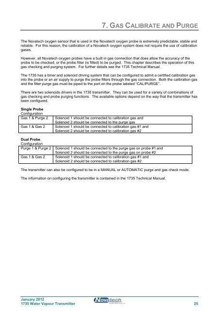
7. GAS CALIBRATE AND PURGE<br />
The <strong>Novatech</strong> oxygen sensor that is used in the <strong>Novatech</strong> oxygen probe is extremely predictable, stable and<br />
reliable. For this reason, the calibration of a <strong>Novatech</strong> oxygen system does not require the use of calibration<br />
gases.<br />
However, all <strong>Novatech</strong> oxygen probes have a built in gas connection that does allow the accuracy of the<br />
probe to be checked, or the probe filter (is fitted) to be purged. This chapter describes the operation of this<br />
gas checking and purging system. For further details see the <strong>1735</strong> Technical <strong>Manual</strong>.<br />
The <strong>1735</strong> has a timer and solenoid driving system that can be configured to admit a certified calibration gas<br />
into the probe or an air supply to purge the probe filters through the gas connection. Both the calibration gas<br />
and the filter purge gas must be piped to the port on the probe labeled “CAL/PURGE”.<br />
There are two solenoids drivers in the <strong>1735</strong> transmitter. They can be used for a variety of combinations of<br />
gas checking and probe purging functions. The available options depend on the way that the transmitter has<br />
been configured.<br />
Single Probe<br />
Configuration<br />
Gas 1 & Purge 2<br />
Gas 1 & Gas 2<br />
Dual Probe<br />
Configuration<br />
Purge 1 & Purge 2<br />
Gas 1 & Gas 2<br />
Solenoid 1 should be connected to calibration gas and<br />
Solenoid 2 should be connected to the purge gas<br />
Solenoid 1 should be connected to calibration gas #1 and<br />
Solenoid 2 should be connected to calibration gas #2<br />
Solenoid 1 should be connected to the purge gas on probe #1 and<br />
Solenoid 2 should be connected to the purge gas on probe #2<br />
Solenoid 1 should be connected to calibration gas #1 and<br />
Solenoid 2 should be connected to calibration gas #2<br />
The transmitter can also be configured to be in a MANUAL or AUTOMATIC purge and gas check mode.<br />
The information on configuring the transmitter is contained in the <strong>1735</strong> Technical <strong>Manual</strong>.<br />
January 2012<br />
<strong>1735</strong> Water Vapour Transmitter 25


