1735 Operators Manual - Novatech Controls
1735 Operators Manual - Novatech Controls
1735 Operators Manual - Novatech Controls
Create successful ePaper yourself
Turn your PDF publications into a flip-book with our unique Google optimized e-Paper software.
4.3.2 Keypad in SETUP Mode<br />
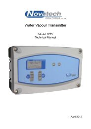
When the SETUP / RUN key is pressed once, the transmitter will go into the SETUP mode.<br />
For information about the additional user-selectable options, see the <strong>1735</strong> Technical <strong>Manual</strong>.<br />
The following key functions are then available in the SETUP mode.<br />
SETUP / RUN Key<br />
Pressing this key once will put the transmitter into the SETUP mode. The function of all the keys will then<br />
change to the functions that they have in the SETUP mode. Pressing the SETUP / RUN key again will return<br />
the transmitter to the RUN mode, or it will return automatically one minute after the last key press.<br />
FUNCTION Up and FUNCTION Down Keys<br />
These two keys allow the selection of the required setup function from the list shown at the start of chapter<br />
5.1 (SETUP mode).<br />
OPTION Up and OPTION Down Keys<br />
These two keys allow for the selection of the options that are available in the selected function. See the<br />
details of these in chapter 5.2 (Setup mode details).<br />
ENTER Key<br />
The ENTER key saves the selected option. If the ENTER key is not pressed when a new option is chosen,<br />
the previous option will be retained.<br />
Probe Impedance Key<br />
When this key is pressed the transmitter will measure the impedance of the sensor in the probe(s). This will<br />
only happen if the burner is enabled (terminals 10 and 11) and the probe temperature is over 700°C<br />
(1290°F).<br />
Auto Calibrate Key<br />
When this key is pressed the transmitter will calibrate the analog output channels. This is done by directing<br />
the output current away from the output terminals (terminals 12 &13 and 14 & 15) and directing the current<br />
back into the transmitter input. The transmitter will then calculate a zero and a span calibration factor for<br />
each of the output channels. The output calibration will only happen if the channel is not set to manual<br />
output calibration. (see Technical <strong>Manual</strong> for more details)<br />
4.3.3 Information Screen<br />
The <strong>1735</strong> transmitter has an information screen available to the user to allow more detailed information<br />
about the running of the transmitter to be easily read by the user.<br />
The information available is:<br />
1. Model and version of the current firmware<br />
2. The date/time that the firmware was compiled<br />
3. The maximum temperature that the transmitter has measured inside the cabinet<br />
4. Current date and time<br />
5. The time of all the next timed events (Impedance test, cal/purge 1, cal/purge 2)<br />
6. ADC calibration data (analogue input calibration)<br />
7. DAC calibration data (analogue output calibration)<br />
8. Probe temperature record (probe 1 and 2)<br />
The information screen is entered from the run mode by pressing (and holding) the ALARM ACCEPT key<br />
and then pressing the SETUP key. The first data appears at the top of the screen and there is a scroll bar<br />
down the left hand side. The data can be scrolled through by using the DISPLAY up and down keys. The<br />
data cannot be changed.<br />
January 2012<br />
16 <strong>1735</strong> Water Vapour Transmitter


