BIO, BIOA, ZIO
BIO, BIOA, ZIO
BIO, BIOA, ZIO

You also want an ePaper? Increase the reach of your titles
YUMPU automatically turns print PDFs into web optimized ePapers that Google loves.
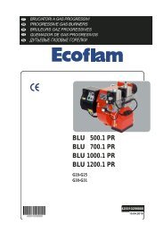
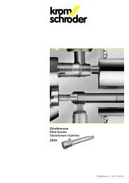
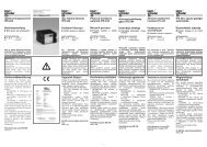
Burners for gas <strong>BIO</strong>, <strong>BIO</strong>A, <strong>ZIO</strong><br />
Technical Information · GB<br />
7.2.14 Edition 12.08<br />
• Large capacity range up to 1000 kW<br />
• Maintenance-friendly thanks to modular design<br />
• Robust burner design<br />
• Direct or lance ignition<br />
• Ionisation control or optionally with UV sensor<br />
• Suitable for new systems and modernisation of existing systems thanks to<br />
individual length adjustment<br />
• Air preheating to 450°C available as an option<br />
• Low polluting level thanks to optimised combustion<br />
• For installation as ceiling or side-wall burner thanks to arbitrary installation<br />
position<br />
• Can be combined with different combustion chamber shapes<br />
www.kromschroeder.com
2<br />
Table of contents<br />
Burners for gas <strong>BIO</strong>, <strong>BIO</strong>A, <strong>ZIO</strong> ...................... 1<br />
Table of contents .................................2<br />
1 Application. ................................... 3<br />
1.1 Examples of application. .........................5<br />
1.1.1 Continuous control with pneumatic ratio control system ...5<br />
1.1.2 Continuous control with pneumatic ratio control system and<br />
lance ................................................5<br />
1.1.3 Continuous control with pneumatic ratio control system ...6<br />
1.1.4 Staged control with pneumatic ratio control system ......6<br />
2 Mechanical construction. .........................7<br />
2.1 Burner housing (furnace flange) ...................7<br />
2.2 Burner insert ..................................7<br />
2.3 Burner tube ...................................8<br />
3 Function. ......................................9<br />
4 Selection .....................................10<br />
4.1 Burner type. ..................................10<br />
4.2 Burner size. ..................................10<br />
4.3 Burner head. ..................................11<br />
4.4 Field of application ............................12<br />
4.5 Calculating the burner tube length ...............13<br />
4.5.1 Burners in burner quarls ...........................13<br />
4.5.2 Burners with burner attachment tube ................16<br />
4.6 Selection table ................................18<br />
4.6.1 Type code .......................................19<br />
5 Project planning information .................... 20<br />
5.1 Installation ...................................20<br />
5.2 Recommended ignition transformer ..............20<br />
5.3 Nozzle-mixing burners .........................20<br />
5.4 Flame control. ................................20<br />
5.5 Hot air compensation. .........................20<br />
5.6 Purging air/cooling air . . . . . . . . . . . . . . . . . . . . . . . . . 21<br />
5.7 Emissions ....................................21<br />
5.8 Gas line connection ...........................22<br />
5.9 Air line connection ............................22<br />
6 Technical data. ............................... 23<br />
6.1 Dimensions ..................................25<br />
6.2 Burner lance .................................27<br />
6.2.1 <strong>BIO</strong> .............................................27<br />
6.2.2 <strong>ZIO</strong> ............................................27<br />
7 Maintenance cycles ........................... 28<br />
Feedback ..................................... 29<br />
Contact. ...................................... 29<br />
<strong>BIO</strong>, <strong>BIO</strong>A, <strong>ZIO</strong> · Edition 12.08<br />
t = To be continued
3<br />
<strong>BIO</strong><br />
1 Application<br />
For industrial furnaces and firing systems in the iron and steel<br />
industries in the precious, non-ferrous and light metal sector,<br />
as well as in the plastics, fibre and paper industries. Other<br />
fields of application are thermal incineration installations, as<br />
well as driers and hot-air generators.<br />
For low temperature applications (e.g. for crucible heating,<br />
radiant tube heating or hot-air generation), the burners are<br />
equipped with a heat-resistant steel attachment tube.<br />
For high temperature applications (e.g. forging furnace), the<br />
burners are used in combination with a burner quarl made<br />
from refractory concrete. Different flame shapes can be<br />
achieved by using burner quarls with a different geometry.<br />
The burner may be adapted to the system requirements using<br />
different burner tube lengths.<br />
<strong>BIO</strong>A<br />
<strong>ZIO</strong><br />
<strong>BIO</strong>, <strong>BIO</strong>A, <strong>ZIO</strong> · Edition 12.08
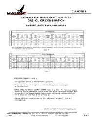
Application<br />
4<br />
Shaft melting and holding furnace Bogie hearth forging furnace Incineration installation for thermal regenerative<br />
flue air purification<br />
Strip galvanising plant Rotary table furnace Aluminium tank furnace<br />
<strong>BIO</strong>, <strong>BIO</strong>A, <strong>ZIO</strong> · Edition 12.08
Application<br />
5<br />
1.1 Examples of application<br />
Threepoint<br />
step<br />
VAS<br />
M<br />
VAG<br />
GEH<br />
EKO<br />
LEH<br />
EKO<br />
<strong>ZIO</strong>, <strong>BIO</strong>, <strong>BIO</strong>A<br />
1.1.1 Continuous control with<br />
pneumatic ratio control system<br />
This type of control offers the benefit of<br />
the mixture setting being maintained<br />
over a wide control range while at the<br />
same time preventing air deficiency.<br />
This type of control is used in melting<br />
furnaces in the aluminium industry or in<br />
regenerative incineration installations in<br />
the environment industry, for example.<br />
IC 20 + BVA<br />
BVA<br />
AKT<br />
VAS<br />
VAG<br />
M<br />
VAS<br />
GEH<br />
GDJ<br />
VR<br />
EKO<br />
GEH<br />
LEH<br />
EKO<br />
<strong>BIO</strong>..L, <strong>ZIO</strong>..L<br />
1.1.2 Continuous control with<br />
pneumatic ratio control system and<br />
lance<br />
The burner’s flexibility is increased thanks<br />
to an ignition lance. The control range<br />
can be extended incrementally with an<br />
optional integrated lance. This type of<br />
control is used in heat treatment furnaces<br />
in the iron and non-ferrous metal<br />
industries and in heating furnaces in the<br />
steel industry, for example.<br />
IC 20..E + BVA<br />
BVA<br />
<strong>BIO</strong>, <strong>BIO</strong>A, <strong>ZIO</strong> · Edition 12.08
Application > Examples of application<br />
6<br />
DG..VC<br />
AKT GFK AKT<br />
DL..A<br />
+ FLS<br />
M<br />
VAS<br />
VAS<br />
VAG<br />
M<br />
IC 20<br />
+ LFC<br />
GEH<br />
EKO<br />
<strong>ZIO</strong>, <strong>BIO</strong>, <strong>BIO</strong>A<br />
1.1.3 Continuous control with<br />
pneumatic ratio control system<br />
The burner is designed for near-stoichiometrical<br />
operation and a control<br />
range of 1:10 with its special burner head<br />
construction for CO2-optimised combustion.<br />
In combination with the cascade<br />
control system, the burner is capable of<br />
operating even with very low connection<br />
ratings, control ranges of 1:45 can be<br />
achieved.<br />
DG..C<br />
IC 20 + BVA<br />
LEH<br />
EKO<br />
AKT<br />
VAG+VBY<br />
MB 7 + BVHM<br />
GEH<br />
EKO<br />
LEH<br />
EKO<br />
<strong>BIO</strong>, <strong>BIO</strong>A, <strong>ZIO</strong><br />
1.1.4 Staged control with pneumatic<br />
ratio control system<br />
The high output pulse at the burner generated<br />
by this type of control produces<br />
a uniform temperature distribution and<br />
good circulation of the furnace or kiln<br />
atmosphere, e.g. in heat treatment furnaces<br />
in the iron and non-ferrous metal<br />
industries or kilns for heavy-clay and fine<br />
ceramics. The pneumatic air/gas ratio<br />
control system offers maximum safety by<br />
an air deficiency cut-out, with a constant<br />
lambda value being maintained while<br />
the air pressure varies.<br />
<strong>BIO</strong>, <strong>BIO</strong>A, <strong>ZIO</strong> · Edition 12.08
7<br />
2 Mechanical construction<br />
The <strong>BIO</strong>, <strong>BIO</strong>A and <strong>ZIO</strong> burners are composed of three modules:<br />
burner housing, burner insert and burner tube. This structure<br />
allows the burners to be easily adapted to the respective process<br />
or to be integrated into existing systems. Maintenance and<br />
repair times are reduced and existing furnace installations<br />
can be easily converted.<br />
2.1 Burner housing (furnace flange)<br />
<strong>BIO</strong> <strong>BIO</strong>A <strong>ZIO</strong><br />
The burner is secured to the furnace by the burner housing.<br />
The burner housing accommodates the burner insert and<br />
the burner tube, and routes the combustion air. The combustion<br />
air pressure can be measured using an air pressure test<br />
nipple.<br />
2.2 Burner insert<br />
<strong>BIO</strong>, <strong>BIO</strong>A<br />
<strong>ZIO</strong><br />
The combustion gas is supplied to the burner head via the<br />
gas connection and the gas pipe. The gas connection flange<br />
comprises of the gauge glass, ground screw and electrode<br />
plugs with plug caps.<br />
As of construction stage E, the connection flange is equipped<br />
with an integrated measuring orifice and flow adjustment for<br />
easy measuring and exact adjusting of the gas flow rate.<br />
The ignition and ionisation electrodes are screwed into the<br />
connection flange and can be replaced without removing the<br />
burner insert as of burner size 65 and construction stage D.<br />
Burners <strong>BIO</strong>, <strong>BIO</strong>A and <strong>ZIO</strong> are nozzle-mixing burners. Gas<br />
and air are mixed only once they are in the burner head. This<br />
prevents explosive gases from being generated in the pipeline.<br />
There are various burner head versions for different flame<br />
shapes and gas types.<br />
<strong>BIO</strong>, <strong>BIO</strong>A, <strong>ZIO</strong> · Edition 12.08
Mechanical construction<br />
8<br />
2.3 Burner tube<br />
Different overall lengths enable adjustment to the system<br />
requirements.<br />
In the burner quarl<br />
The burner head is positioned inside the burner tube. The<br />
burner quarl accommodates the burner tube and simultaneously<br />
acts as the combustion chamber for the complete<br />
combustion of the flame.<br />
With attachment tube<br />
The burner head is positioned inside the burner tube. An attachment<br />
tube made of heat-resistant steel acts as the combustion<br />
chamber for the complete combustion of the flame<br />
for low- and medium-temperature applications.<br />
<strong>BIO</strong>, <strong>BIO</strong>A, <strong>ZIO</strong> · Edition 12.08
9<br />
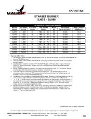
3 Function<br />
The burner control unit opens the gas and air control valves.<br />
Gas flows through the gas connection flange and air flows<br />
through the burner housing as far as the nozzle-mixing burner<br />
head.<br />
The combustible gas/air mixture is produced downstream of<br />
the burner head. Slots and holes in the air disc vary the degree<br />
and manner of twisting of the combustion air and determine<br />
the flame geometry. Depending on the gas type, the geometry<br />
of the gas nozzle varies.<br />
The gas/air mixture is electrically ignited directly by an ignition<br />
electrode or an ignition lance. A flame forms which is<br />
monitored using an ionisation electrode or optionally using<br />
the UV sensor.<br />
The choice of the respective combustion chamber material<br />
and geometry is primarily determined by the process.<br />
Using burner quarls, almost any flame shape and outlet velocity<br />
can be achieved.<br />
For low-temperature applications, a combustion chamber<br />
made of heat-resistant steel is used. The combustion chamber<br />
is part of the metallic burner attachment tube.<br />
<strong>BIO</strong>, <strong>BIO</strong>A<br />
<strong>ZIO</strong><br />
Burner insert<br />
Gas<br />
Burner housing<br />
Burner insert<br />
Gas<br />
Air<br />
Burner housing<br />
Air<br />
Burner head<br />
Burner tube<br />
Burner head<br />
Burner tube<br />
Burner head<br />
Ignition electrode<br />
Ionisation electrode<br />
Gas nozzle<br />
<strong>BIO</strong>, <strong>BIO</strong>A, <strong>ZIO</strong> · Edition 12.08
10<br />
4 Selection<br />
4.1 Burner type<br />
Type<br />
Housing<br />
Air temperature Furnace temperature<br />
°C °C<br />
<strong>BIO</strong> GG 25 20 to 450 50 to 1600<br />
<strong>BIO</strong>A AlSi 20 to 200 50 to 1400<br />
<strong>ZIO</strong> ST 20 to 450 50 to 1600<br />
4.2 Burner size<br />
Burner size<br />
Burner capacity<br />
[kW]<br />
<strong>BIO</strong> 50 40<br />
<strong>BIO</strong>, <strong>BIO</strong>A 65 90<br />
<strong>BIO</strong> 80 150<br />
<strong>BIO</strong> 100 230<br />
<strong>BIO</strong> 125 320<br />
<strong>BIO</strong> 140 450<br />
<strong>ZIO</strong> 165 630<br />
<strong>ZIO</strong> 200 1000<br />
<strong>BIO</strong>, <strong>BIO</strong>A, <strong>ZIO</strong> · Edition 12.08
Selection<br />
11<br />
4.3 Burner head<br />
The choice of burner head depends on the flame shape, gas type and variant.<br />
Flame shape<br />
Control range<br />
Code letter<br />
Furnace<br />
Air<br />
burnerhead Continuous<br />
volume<br />
Constant air<br />
Low fi re λ λ 2) temperature temperature 3)<br />
Staged<br />
[°C]<br />
[°C]<br />
normal R 1:10 1:3 > 1:10 > 1.05 0.8 – 1.3 50 – 1350 20 – 150 5)<br />
long H 1:10 1:4 1:10 > 1.3 0.8 – 1.5 500 – 1600 20 – 450<br />
fl at K 4) – – > 1:10 > 1.05 0.9 – 1.2 50 – 1100 5) 20 – 150 5)<br />
1) Standard version, for larger control ranges, see under Variant.<br />
2) Indicate the rough range for the max. connection rating. For precise values for the individual versions, see burner diagrams. The ranges were determined<br />
for an ionisation current ≥ 5 μA. Extension of the working range using a UV sensor.<br />
3) The gas fl ow rate should be reduced in accordance with the enthalpy gain of the preheated combustion air.<br />
4) In conjunction with a burner quarl, for use as a radiant burner.<br />
5) Higher temperatures available on request.<br />
Gas type<br />
Code letter<br />
Calorifi c value range<br />
kWh/m 3 (n)<br />
Densitiy ρ<br />
kg/m 3<br />
Natural gas L and H quality B 8 to12 0.7 to 0.9<br />
Propane, propane/butane, butane M 25 to 35 2.0 to 2.1<br />
Propane, propane/butane, butane G 1) 25 to 35 2.0 to 2.1<br />
Town gas, coke oven gas D 4 to 5 0.4 to 0.6<br />
Low calorifi c value gas L 2) 1.7 3) to 2.5 0.9 to 1.15<br />
1) For <strong>BIO</strong> 50.<br />
2) Not for all burner sizes. Burner capacity is limited to 50% of the rated capacity.<br />
3) Calorifi c value range < 1.7 on request.<br />
Variant Code letter Low fi re<br />
Output<br />
[kW]<br />
λ<br />
Separate low-fi re gas and air rate supply L approx. 1.5 > 1.05<br />
Reduced max. connection rating R – > 1.05<br />
<strong>BIO</strong>, <strong>BIO</strong>A, <strong>ZIO</strong> · Edition 12.08
Selection<br />
12<br />
4.4 Field of application<br />
Field of application Illustration*<br />
Combustion<br />
chamber<br />
Industrial furnaces, open<br />
combustion chambers 4) A Open cone<br />
Industrial furnaces, open<br />
combustion chambers 4) B Cylindrical<br />
Industrial furnaces, open<br />
combustion chambers 4) C Tapered<br />
Industrial furnaces, open<br />
combustion chambers 4) D Flat fl ame quarl<br />
Crucible heating E Cylindrical<br />
Radiant tube heating<br />
1), 2), 3) F<br />
Hot-air generation<br />
1), 3) G<br />
Burner attachment<br />
tube with<br />
purging air bore<br />
holes<br />
Burner attachment<br />
tube with<br />
purging air bore<br />
holes, protective<br />
fl ame tube FPT<br />
Control<br />
High/Low<br />
Continuous<br />
High/Low<br />
High/Low/Off<br />
Continuous<br />
High/Low<br />
High/Low/Off<br />
Continuous<br />
High/Low<br />
High/Low/Off<br />
Continuous<br />
High/Low<br />
High/Low/Off<br />
Continuous<br />
Burner<br />
head type<br />
Max.<br />
capacity<br />
R 100 %<br />
Note<br />
Recommended for cold-air operating mode only,<br />
otherwise the nitric oxide values are too high<br />
R, H 100 % Normal to medium fl ow velocity<br />
R, H ca. 80 %<br />
K 100 %<br />
H 100 %<br />
On/High/Off H 100 %<br />
High/Low<br />
High/Low/Off<br />
Continuous<br />
R 100 %<br />
Medium to high velocity, capacity depending<br />
on the diameter<br />
In the case of continuous control, usage in<br />
the lower capacity range (≥ 40%) is restricted,<br />
depending on the burner<br />
The connection rating of the burners is<br />
chiefl y dependent on the capacity of the<br />
burner chamber.<br />
The connection rating of the burners is<br />
chiefl y dependent on the capacity of the<br />
burner chamber, usually < 2.5 W/cm². A<br />
draught blocker must be fi tted on the fl ue<br />
gas side.<br />
Protection of the fl ame from cooling is ensured<br />
by using a protective fl ame tube FPT<br />
(recommended for fl ow velocity of<br />
> 15 m/s)<br />
* See burner with attachment tube or burner quarl type.<br />
1) When using the burners in radiant tubes or in small combustion chambers, a trial under operating conditions is recommended. The burners must be<br />
secured gas-tight to the furnace or burner quarl by the furnace fl ange, so that a backfl ow of hot fl ue gases is avoided.<br />
2) The outlet diameter of the radiant tube must be reduced to the point where a pressure loss of approx. 10 mbar occurs at max. burner capacity.<br />
3) Only where the furnace temperature is < 600°C.<br />
4) For optimal operation, the burner quarl and the fl ame shapes are combined according to the fi eld of application (see Burners in burner quarls).<br />
<strong>BIO</strong>, <strong>BIO</strong>A, <strong>ZIO</strong> · Edition 12.08
Selection<br />
13<br />
4.5 Calculating the burner tube length<br />
4.5.1 Burners in burner quarls<br />
<strong>BIO</strong>, <strong>BIO</strong>A, <strong>ZIO</strong> Burner quarl type Gas type*<br />
Flame shape<br />
Burner head**<br />
Burner<br />
chamber<br />
length BKL<br />
(L 10 )<br />
[mm]<br />
50 A B, G, D R 215 to 265<br />
50 B, C B, G, D R 115 to 265<br />
50 B, C B, G H 115 to 265<br />
50 D B K 130 to 135<br />
65 A B, M, G, D R 215 to 265<br />
65 B, C B, M, G, D R 115 to 265<br />
65 B, C B, M, G, D H 115 to 265<br />
65 D B, M, D K 155 to 175<br />
80 A B, M R 215 to 265<br />
80 B, C B, M R 165 to 265<br />
80 B, C B, M H 165 to 265<br />
80 D B, M K 205 to 225<br />
100 A B, G, M, D R 215 to 315<br />
100 B, C B, G, M, D R 165 to 265<br />
100 B, C B, G, M, D H 165 to 315<br />
100 D B, M K 230 to 250<br />
100 D D K 170 to 190<br />
125 A B, M, G R 265 to 365<br />
125 B, C B, M, G R 215 to 315<br />
125 B, C B, M H 215 to 365<br />
125 D B K 190 to 210<br />
* B = natural gas, M = butane, butane/propane, propane, D = town gas,<br />
G = propane, propane/butane<br />
** Flame shape: R = normal, H = long, K = fl at<br />
Burner quarl type<br />
BKL<br />
BKL<br />
BKL<br />
BKL<br />
∅<br />
A<br />
B<br />
C<br />
D<br />
<strong>BIO</strong>, <strong>BIO</strong>A, <strong>ZIO</strong> · Edition 12.08
14<br />
<strong>BIO</strong>, <strong>BIO</strong>A, <strong>ZIO</strong> Burner quarl type Gas type*<br />
Flame shape<br />
Burner head**<br />
Burner<br />
chamber<br />
length BKL<br />
(L 10 )<br />
[mm]<br />
140 A B, M, D R 315 to 415<br />
140 B, C B, M, D R 265 to 365<br />
140 B, C B, M, G, D H 265 to 415<br />
140 D B, M K 215 to 235<br />
165 A B, M R 315 to 465<br />
165 B B, M R 265 to 415<br />
165 B, C B, M, D H 265 to 465<br />
165 D B, M K 240 to 260<br />
200 A B, M R 415 to 565<br />
200 B B, M R 315 to 465<br />
200 B, C B, M, D H 315 to 565<br />
200 D B K 255 to 275<br />
* B = natural gas, M = butane, butane/propane, propane, D = town gas,<br />
G = propane, propane/butane<br />
** Flame shape: R = normal, H = long, K = fl at<br />
For further information on burner quarls – see www.docuthek.com<br />
BKL<br />
BKL<br />
BKL<br />
BKL<br />
∅<br />
A<br />
B<br />
C<br />
D<br />
<strong>BIO</strong>, <strong>BIO</strong>A, <strong>ZIO</strong> · Edition 12.08
Selection > Calculating the burner tube length > Burners in burner quarls<br />
15<br />
L1<br />
L2<br />
L O<br />
max. 10°<br />
BKL<br />
Legend<br />
L1 = Burner tube length<br />
L2 = Position of burner head<br />
L O = Furnace wall thickness<br />
BKL = Burner chamber length (L10)<br />
The position of the burner head (L2) should be appropriately selected, so that the<br />
burner head extends into the burner quarl.<br />
The position of the burner head is available in the following lengths: 35, 135, 235,<br />
335 mm, etc.<br />
Determine the position of the burner head: L2 = L O - BKL<br />
The burner tube length (L1) is predefined, depending on the flame shape R, K or H:<br />
R, K burner head: L1 = L2 + 15 mm<br />
H burner head: L1 = L2 + 65 mm<br />
Example<br />
Desired flame shape = R (normal).<br />
Selected burner with 40 kW capacity = <strong>BIO</strong> 50,<br />
the related burner chamber length (BKL) = 115 to 265 mm.<br />
Furnace wall thickness L O = 340 mm.<br />
Determine the position of the burner head:<br />
L2 = L O - BKL = 340 mm - 115 mm = 225 mm.<br />
Take the next smallest position of the burner head (L2):<br />
calculated position of the burner head = 225 mm ➔ next smallest position of the<br />
burner head = 135 mm.<br />
Test whether the burner chamber length (BKL) fits:<br />
furnace wall thickness – next smallest position of the burner head = burner<br />
chamber length<br />
L O - L2 = BKL ➔ 340 mm - 135 mm = 205 mm.<br />
The required BKL for burners <strong>BIO</strong> 50 with a furnace wall thickness of 340 mm<br />
and a burner head position of 135 mm is 205 mm. 205 mm falls into the burner<br />
chamber length range for burners <strong>BIO</strong> 50: 115 to 265 mm (see table Burners in<br />
burner quarls).<br />
<strong>BIO</strong>, <strong>BIO</strong>A, <strong>ZIO</strong> · Edition 12.08
Selection > Calculating the burner tube length<br />
16<br />
4.5.2 Burners with burner attachment tube<br />
Examples for fields of application<br />
E F G<br />
Crucible heating Radiant tube heating Hot-air generation<br />
<strong>BIO</strong>, <strong>BIO</strong>A, <strong>ZIO</strong> · Edition 12.08
Selection > Calculating the burner tube length > Burners with burner attachment tube<br />
17<br />
L1<br />
L O<br />
L2 L 1-2<br />
Legend<br />
L1 = Burner tube length<br />
L2 = Position of burner head<br />
LO = Furnace wall thickness<br />
L 1-2 = Distance from burner head to<br />
burner tube end<br />
Distance from burner head to burner tube end (L 1-2 ):<br />
<strong>BIO</strong>, <strong>BIO</strong>A, <strong>ZIO</strong><br />
H burner head<br />
R burner head<br />
[mm]<br />
[mm]<br />
50 115 115<br />
65 115 115<br />
80 165 165<br />
100 165 165<br />
125 215 215<br />
140 265 265<br />
165 265 165<br />
200 315 215<br />
Position of burner head:<br />
L2 = L O ± 50 mm<br />
The burner tube length (L1) is calculated by adding the position of the burner<br />
head (L2) to the distance from burner head to burner tube end (L 1-2 ):<br />
L1 = L2 + L 1-2<br />
Example<br />
Desired flame shape = R (normal).<br />
Selected burner with 40 kW capacity = <strong>BIO</strong> 50,<br />
the related distance from burner head to burner tube end (L 1-2 ) = 115 mm.<br />
Available furnace wall thickness L O = 250 mm.<br />
Determine the position of the burner head:<br />
L2 = L O - 50 mm = 250 - 50 mm = 200 mm.<br />
Take the next largest position of the burner head (L2):<br />
calculated position of the burner head = 200 mm ➔ next largest position of the<br />
burner head = 235 mm.<br />
Calculate the related burner tube length (L1):<br />
L1 = L2 + L 1-2 = 235 mm + 115 mm = 350 mm.<br />
<strong>BIO</strong>, <strong>BIO</strong>A, <strong>ZIO</strong> · Edition 12.08
Selection<br />
18<br />
4.6 Selection table<br />
50 65 80 100 125 140 165 200 H R K B G M L D L - 50 –… /35 – … -(1) – -(99) A – Z B<br />
<strong>BIO</strong> <br />
<strong>BIO</strong>A <br />
<strong>ZIO</strong> <br />
= standard, = available<br />
Order example<br />
<strong>ZIO</strong> 165RB-50/35-(17)D<br />
<strong>BIO</strong>, <strong>BIO</strong>A, <strong>ZIO</strong> · Edition 12.08
Selection > Selection table<br />
19<br />
4.6.1 Type code<br />
Code<br />
Description<br />
<strong>BIO</strong><br />
Burner for gas<br />
<strong>BIO</strong>A<br />
Burner for gas with aluminium housing<br />
<strong>ZIO</strong><br />
Burner for gas<br />
50 to 200 Burner size<br />
Flame shape:<br />
H<br />
Long<br />
R<br />
Normal<br />
K<br />
Flat<br />
B<br />
G<br />
M<br />
L<br />
D<br />
Gas type:<br />
Natural gas<br />
Propane, propane/butane<br />
Butane, butane/propane<br />
Low calorifi c value gas<br />
Town gas<br />
Variant:<br />
Separate low-fi re gas and air rate supply<br />
Reduced max. connection rating<br />
L<br />
R<br />
–50*<br />
–100**<br />
–150*<br />
–200**<br />
Burner tube length [mm]<br />
–250*<br />
–300**<br />
to<br />
/35–<br />
/135–<br />
Position of burner head<br />
/235–<br />
to<br />
-(1) to -(99) Burner head identifi er<br />
A to F<br />
Construction stage<br />
B<br />
With purging air bore holes<br />
* R-, K burner head<br />
** H burner head<br />
<strong>BIO</strong>, <strong>BIO</strong>A, <strong>ZIO</strong> · Edition 12.08
20<br />
5 Project planning information<br />
5.1 Installation<br />
Installation position: any.<br />
Gas and air connection: can be rotated in 90° steps.<br />
Install and insulate the burner in order to avoid any overheating<br />
of the components during operation. Where applicable,<br />
purging air must be used to prevent ingress of aggressive<br />
gases and thermal overload of components.<br />
Purging air bore holes in the furnace flange area ensure cooling<br />
and stability in the case of combustion in small combustion<br />
chambers (for example radiant tubes).<br />
5.2 Recommended ignition transformer<br />
≥ 7.5 kV, ≥ 12 mA, e.g. TZI 7,5-12/100 or TGI 7,5-12/100.<br />
5.3 Nozzle-mixing burners<br />
Non-return gas valves are not required, since the burners are<br />
of the nozzle-mixing type.<br />
5.4 Flame control<br />
Flame control is performed using an ionisation electrode or<br />
optionally using a UV sensor.<br />
5.5 Hot air compensation<br />
In order to maintain the total connection rating constant in<br />
hot-air operating mode:<br />
1. Gas connection rating and gas pressure are reduced<br />
Total connection rating [%]<br />
100<br />
96<br />
90<br />
85<br />
80<br />
75<br />
0 50 100 150 200 250 300 350 400 450<br />
Combustion air temperature [°C]<br />
2. Air pressure is increased<br />
air pressure [%]<br />
200<br />
180<br />
160<br />
140<br />
120<br />
Gas connection rating<br />
Gas pressure<br />
100<br />
0 50 100 150 200 250 300 350 400 450<br />
Combustion air temperature [°C]<br />
<strong>BIO</strong>, <strong>BIO</strong>A, <strong>ZIO</strong> · Edition 12.08
Project planning information<br />
21<br />
5.6 Purging air/cooling air<br />
Cooling air at 20°C<br />
Air volume at rated capacity [%]<br />
Purging/cooling air volume for burner<br />
6<br />
5<br />
4<br />
3<br />
2<br />
1<br />
<strong>BIO</strong>/<strong>ZIO</strong>..K<br />
<strong>BIO</strong>, <strong>ZIO</strong><br />
<strong>BIO</strong>/<strong>ZIO</strong>..KB..E<br />
0<br />
0<br />
700 800 900 1000 1100 1200 1300 1400<br />
Furnace temperature °C<br />
Purging air<br />
Depending on the furnace temperature, the burner must be<br />
cooled with a low air volume, being switched off, in order to<br />
avoid condensation due to the furnace atmosphere entering<br />
the burner housing. The air fan should not be switched off<br />
until the furnace has cooled down completely.<br />
Cooling air<br />
Thermal overload of the burner components must be avoided<br />
while the burner is switched off. The cooling air volume depends<br />
on the furnace and cooling air temperatures.<br />
The cooling air volumes in the diagram are given in standard<br />
cubic metres.<br />
12<br />
10<br />
8<br />
6<br />
4<br />
2<br />
Cooling air at 450°C<br />
Air volume at rated capacity [%]<br />
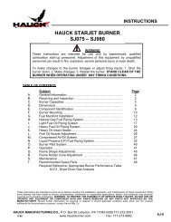
5.7 Emissions<br />
NOX<br />
[mg/m3]<br />
5% O2<br />
600<br />
500<br />
400<br />
300<br />
200<br />
100<br />
70<br />
50<br />
K (450 °C)<br />
H (450 °C)<br />
R, K (20 °C)<br />
H (20 °C)<br />
10 50 100<br />
Capacity [%]<br />
Flame shape:<br />
R = Normal<br />
H = Long<br />
K = Flat<br />
T Furnace<br />
= 1000°C<br />
Emissions for cold-air operating mode do not exceed the limits<br />
stipulated by the German Clean Air Directive.<br />
NO X values depend on the temperature, burner head, combustion<br />
chamber, furnace chamber, λ value and output (NO X<br />
values on request).<br />
If operated with LPG, NO X values are approx. 25% higher.<br />
<strong>BIO</strong>, <strong>BIO</strong>A, <strong>ZIO</strong> · Edition 12.08
Project planning information<br />
22<br />
5.8 Gas line connection<br />
To ensure accurate measurements of the pressure differential<br />
on the integrated gas measuring orifice for burners <strong>BIO</strong> as<br />
from construction stage E, the following applies for the design<br />
of the gas connection:<br />
– Ensure undisturbed flow to the gas connection on the burner<br />
for a distance of ≥ 5 DN.<br />
– Use a bellows unit with the same nominal dimensions as<br />
the gas connection on the burner.<br />
– Use a pipe bend up to an angle of 90° with the same nominal<br />
dimensions as the gas connection on the burner.<br />
– Only use reducing nipples with an external thread at both<br />
ends in order to reduce the nominal diameter on the burner<br />
(e.g. from 1” to ¾”).<br />
To ensure optimum flow, to avoid incorrect measurements and<br />
to enable burner operation with excess gas, we recommend<br />
the following:<br />
– Do not screw the manual valve directly into the burner.<br />
5.9 Air line connection<br />
Ensure there is a bellows unit and an air adjusting cock upstream<br />
of the burner. It is recommended to install a measuring<br />
orifice FLS to determine the air flow rate.<br />
<strong>BIO</strong>, <strong>BIO</strong>A, <strong>ZIO</strong> · Edition 12.08
23<br />
6 Technical data<br />
Gas supply pressure: approx. 20 to 60 mbar,<br />
Air supply pressure: approx. 25 to 40 mbar,<br />
each depending on flame shape and gas type (gas and air<br />
pressures – see burner diagrams at www.docuthek.com).<br />
Burner length increments: 100 mm.<br />
Types of gas: natural gas or LPG (gaseous); other gases on<br />
request.<br />
Heating: direct using a burner quarl or an attachment tube,<br />
indirect using a burner attachment tube inside the radiant<br />
tube.<br />
Control type:<br />
staged: On/Off, High/Low/Off,<br />
continuous: constant λ value.<br />
Most of the burner components are made of corrosionresistant<br />
stainless steel.<br />
Housing:<br />
<strong>BIO</strong>: GG25,<br />
<strong>BIO</strong>A: AlSi,<br />
<strong>ZIO</strong>: ST.<br />
Flame control: direct ionisation control (UV control as an option).<br />
Ignition: direct, electrical, lance as an option.<br />
Maximum furnace temperature:<br />
<strong>BIO</strong>/<strong>ZIO</strong> in burner quarl: up to 1600°C,<br />
with K burner head: up to 1100°C (higher temperatures on<br />
request),<br />
<strong>BIO</strong>/<strong>ZIO</strong> with burner attachment tube: up to 800°C (higher<br />
temperatures on request).<br />
Maximum air temperature:<br />
<strong>BIO</strong>, <strong>ZIO</strong>: 450°C,<br />
<strong>BIO</strong>A: 200°C.<br />
<strong>BIO</strong>, <strong>BIO</strong>A, <strong>ZIO</strong> · Edition 12.08
Technical data<br />
24<br />
Burner Rated capacity 1) Flame shape<br />
code letter<br />
Flame length 2) Flame outlet velocity 3)<br />
kW cm m/s<br />
<strong>BIO</strong> 50 40 R 30 15<br />
<strong>BIO</strong> 50 40 H 35 50<br />
<strong>BIO</strong> 65 90 R 40 20<br />
<strong>BIO</strong>A 65 90 R 40 20<br />
<strong>BIO</strong> 65 90 H 60 65<br />
<strong>BIO</strong>A 65 90 H 60 65<br />
<strong>BIO</strong> 65 90 K – –<br />
<strong>BIO</strong> 80 150 R 45 20<br />
<strong>BIO</strong> 80 150 H 70 70<br />
<strong>BIO</strong> 80 150 K – –<br />
<strong>BIO</strong> 100 230 R 55 20<br />
<strong>BIO</strong> 100 230 H 80 70<br />
<strong>BIO</strong> 100 230 K – –<br />
<strong>BIO</strong> 125 320 R 55 20<br />
<strong>BIO</strong> 125 320 H 115 60<br />
<strong>BIO</strong> 140 450 R 80 20<br />
<strong>BIO</strong> 140 450 H 140 70<br />
<strong>BIO</strong> 140 450 K – –<br />
<strong>ZIO</strong> 165 630 R 80 20<br />
<strong>ZIO</strong> 165 630 H 160 70<br />
<strong>ZIO</strong> 165 630 K – –<br />
<strong>ZIO</strong> 200 1000 R 100 25<br />
<strong>ZIO</strong> 200 1000 H 200 80<br />
1) Higher capacities are possible – either on request or see burner diagrams at www.docuthek.com.<br />
2) Measured in the burner quarl from the front edge of the burner quarl, 6° open cone for R head, cylindrical for H head. The fl ame diameter is approx.<br />
one to two times that of the burner tube or burner quarl outlet.<br />
3) Referred to rated capacity, with a fl ame temperature of 1600°C for R burner head and 1500°C for H burner head. The fl ow velocity is increased when the<br />
outlet diameter of the burner quarl is reduced. The rated capacity must then be adjusted to the outlet diameter.<br />
<strong>BIO</strong>, <strong>BIO</strong>A, <strong>ZIO</strong> · Edition 12.08
Technical data<br />
25<br />
6.1 Dimensions<br />
d3<br />
n3<br />
h H<br />
LA<br />
L5<br />
k3<br />
D3<br />
L3<br />
S<br />
D<br />
d2<br />
F<br />
n2<br />
h H 30<br />
GA<br />
LA<br />
L5<br />
L3<br />
S<br />
D<br />
d2<br />
F<br />
n2<br />
GA<br />
L4<br />
L6<br />
L2<br />
L1<br />
k2<br />
D2<br />
L6<br />
L4<br />
L2<br />
L1<br />
k2<br />
D2<br />
L1 (burner tube length) and L2 (position of burner head) are variable (see Calculating the burner tube length)<br />
<strong>BIO</strong><br />
<strong>BIO</strong>A<br />
Burner<br />
Max.<br />
Dimensions [mm]<br />
capacity*<br />
Gas connection<br />
Air connection<br />
Weight<br />
[kW] D** GA LA H h S L3 L4 L5 L6 D2 k2 d2 n2 F D3 k3 d3 n3 [kg]<br />
<strong>BIO</strong> 50 40 50 Rp 1 / 2 Rp 1 1 / 2 50 38 12 73 149 240 127 181 151 12 4 75 – – – – 5.4<br />
<strong>BIO</strong> 65 90 65 Rp 3 / 4 Rp 1 1 / 2 62 48 12 73 156 246 127 195 165 12 4 95 – – – – 7.2<br />
<strong>BIO</strong>A 65 90 65 Rp 1 / 2 ∅ 48 80 44 16 95 170 261 149 195 165 13 4 88 – – – – 3.6<br />
<strong>BIO</strong> 80 150 82 Rp 3 / 4 Rp 2 112 55 14 90 172 272 140 240 210 14 4 110 – – – – 11.2<br />
<strong>BIO</strong> 100 230 100 Rp 1 Rp 2 100 60 16 103 185 285 153 240 200 14 4 120 – – – – 12.6<br />
<strong>BIO</strong> 125 320 127 Rp 1 1 / 2 DN 65 135 73 16 120 254 350 212 270 240 14 4 145 185 145 18 4 21.7<br />
<strong>BIO</strong> 140 450 140 Rp 1 1 / 2 DN 80 150 80 18 130 271 381 232 300 265 14 4 160 200 160 18 8 29<br />
* Cold-air connection, open fl ame, λ = 1,1<br />
** Approx. 10 cm larger in the case of a deviation from the standard length, as a weld seam is applied.<br />
<strong>BIO</strong>, <strong>BIO</strong>A, <strong>ZIO</strong> · Edition 12.08
Technical data > Dimensions<br />
26<br />
L6<br />
S<br />
d2<br />
F<br />
n2<br />
D<br />
Z<br />
I<br />
d3<br />
H<br />
GA<br />
L4<br />
LA<br />
D3<br />
k3<br />
L3<br />
L2<br />
L1<br />
k2<br />
D2<br />
<strong>ZIO</strong><br />
Burner<br />
Max.<br />
Dimensions [mm]<br />
capacity*<br />
Gas connection<br />
Air connection<br />
Weight<br />
[kW] D** GA LA H h S L3 L4 L5 L6 D2 k2 d2 n2 F D3 k3 d3 n3 [kg]<br />
<strong>ZIO</strong> 165 630 165 R 1 1 / 2 DN 100 213 – 20 150 359 – 230 285 240 14 4 ∅ 220 220 180 18 8 26<br />
<strong>ZIO</strong> 200 1000 194 R 2 DN 150 220 – 20 220 469 – 340 330 295 22 8 ∅ 255 285 240 22 8 37<br />
* Cold-air connection, open fl ame, λ = 1,1<br />
** Approx. 10 cm larger in the case of a deviation from the standard length, as a weld seam is applied.<br />
<strong>BIO</strong>, <strong>BIO</strong>A, <strong>ZIO</strong> · Edition 12.08
Technical data<br />
27<br />
6.2 Burner lance<br />
6.2.1 <strong>BIO</strong><br />
Gas connection: Rp ¼.<br />
Air connection: Rp 3/8.<br />
Gas pressure: 30 to 50 mbar.<br />
Air pressure: 30 to 50 mbar.<br />
L7<br />
6.2.2 <strong>ZIO</strong><br />
Gas connection: Rp ¼.<br />
Air connection: Rp ½.<br />
Air<br />
L7<br />
B<br />
E2<br />
B<br />
gas<br />
E1<br />
I<br />
Z<br />
C<br />
E1<br />
W1<br />
I<br />
I<br />
Z<br />
Gas<br />
W2<br />
Burner<br />
air<br />
C<br />
Gas Air<br />
connection connection<br />
Dimensions<br />
B C E1 E2 L7 W1 W2<br />
mm mm mm mm mm ∠ ° ∠ °<br />
<strong>BIO</strong> 80..L 57 54 7 10 177 36 45<br />
<strong>BIO</strong> 100..L 57 54 7 10 190 36 45<br />
<strong>BIO</strong> 125..L 69 65 8 8 261 30 30<br />
<strong>BIO</strong> 140..L 63 62 16 18 276 42 45<br />
E2<br />
Burner<br />
Gas Air<br />
connection connection<br />
Dimensions<br />
B C E1 E2 L7<br />
mm mm mm mm mm<br />
<strong>BIO</strong> 165..L 118 77 27 71 382<br />
<strong>BIO</strong> 200..L 137 77 27 89 482<br />
<strong>BIO</strong>, <strong>BIO</strong>A, <strong>ZIO</strong> · Edition 12.08
28<br />
7<br />
Maintenance cycles<br />
Twice per year, but if the media are highly contaminated, this<br />
interval should be reduced.<br />
<strong>BIO</strong>, <strong>BIO</strong>A, <strong>ZIO</strong> · Edition 12.08
Feedback<br />
Finally, we are offering you the opportunity to assess this “Technical Information (TI)” and to give us your opinion, so that we<br />
can improve our documents further and suit them to your needs.<br />
Clarity<br />
Found information quickly<br />
Searched for a long time<br />
Didn’t find information<br />
What is missing?<br />
No answer<br />
Comprehension<br />
Coherent<br />
Too complicated<br />
No answer<br />
Scope<br />
Too little<br />
Sufficient<br />
Too wide<br />
No answer<br />
29<br />
Use<br />
To get to know the product<br />
To choose a product<br />
Planning<br />
To look for information<br />
Navigation<br />
I can find my way around<br />
I got “lost”<br />
No answer<br />
My scope of functions<br />
Technical department<br />
Sales<br />
No answer<br />
Remarks<br />
(Adobe Reader 7 or higher required)<br />
1 Contact<br />
Elster GmbH<br />
Postfach 2809 · 49018 Osnabrück<br />
Strotheweg 1 · 49504 Lotte (Büren)<br />
Germany<br />
T +49 541 1214-0<br />
F +49 541 1214-370<br />
info@kromschroeder.com<br />
www.kromschroeder.com<br />
www.elster.com<br />
The current addresses of our international<br />
agents are available on the Internet:<br />
www.kromschroeder.com Sales<br />
Kromschröder, a product<br />
brand of the Elster Group<br />
We reserve the right to make technical<br />
modifications in the interests of progress.<br />
Copyright © 2007 Elster Group<br />
All rights reserved.<br />
03250786<br />
<strong>BIO</strong>, <strong>BIO</strong>A, <strong>ZIO</strong> · Edition 12.08