- Page 1:
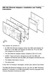
April 2011 IMPORTANT 1. The motherb
- Page 5 and 6:
FEDERAL COMMUNICATIONS COMMISSION R
- Page 8 and 9:
CONTENTS SECTION 1. HARDWARE OVERV
- Page 10 and 11:
Programming Considerations ........
- Page 12 and 13:
INS 8250 Functional Pin Description
- Page 14 and 15:
FIGURE LISTING 1. System Block Dia
- Page 16 and 17:
SECTION I. HARDWARE OVERVIEW The
- Page 18 and 19:
The 16KB Memory Expansion Kits allo
- Page 20 and 21:
SECTION 2. HARDWARE ~ Contents: Sys
- Page 22 and 23:
SYSTEM BOARD The System Board fits
- Page 24 and 25:
The memory is dynamic 16K x 1 chips
- Page 26 and 27:
System Board Data Flow Figure 2. S
- Page 28 and 29:
1/0 Channel Diagram REAR PANEl SI
- Page 30 and 31:
I/O CHRDY I I/O Channel Ready: This
- Page 32 and 33:
System Board Component Diagram REA
- Page 34 and 35:
Keyboard Interface B lock Diagram
- Page 36 and 37:
1 2 3 4 5 6 7 8 9 10 11 12 13 14 15
- Page 38 and 39:
Cassette User Interface The cassett
- Page 40 and 41:
Cassette Interface Connector Specif
- Page 42 and 43:
I/O Address Map HEX RANGE 9 8 7 6
- Page 44 and 45:
System Memory Map X'OOOOO' 16 TO 6
- Page 46 and 47:
System Memory Map Cont. START ADDR
- Page 48 and 49:
5-1/4" Diskette Drives Switch Setti
- Page 50 and 51:
32/64KB Memory Expansion Option Sw
- Page 52 and 53:
Power Supply The system DC power su
- Page 54 and 55:
N I ~ VI ) § I • \. ~ o el so.
- Page 56 and 57:
IBM Monochrome Display and Parallel
- Page 58 and 59:
System Channel Interface Lines Used
- Page 60 and 61:
Programming Considerations Programm
- Page 62 and 63:
• CRT Status Port (I/O Address '3
- Page 64 and 65:
Color/Graphics Monitor Adapter The
- Page 66 and 67:
CPU .. r-- ) ) ) DISPLAY ADDRESS BU
- Page 68 and 69:
Modes of Operation There are two ba
- Page 70 and 71:
IBM Monochrome Display Adapter V s.
- Page 72 and 73:
Color selection is determined by th
- Page 74 and 75:
1"'"""""\ Table 5. I R G B Summary
- Page 76 and 77:
Programming the Mode Control and St
- Page 78 and 79:
Bit 5 When on, this bit will change
- Page 80 and 81:
I/O Address and Bit Map Read/Write
- Page 82 and 83:
Color/Graphics Monitor Adapter Auxi
- Page 84 and 85:
Parallel Printer Adapter The Printe
- Page 86 and 87:
Programming Considerations The Prin
- Page 88 and 89:
Parallel Printer Adapter Interface
- Page 90 and 91:
Table 7. Printer Specifications (1
- Page 92 and 93:
Table 9. Functions and Conditions o
- Page 94 and 95:
Table 10. Connector Pin Assignment
- Page 96 and 97:
(4) Data transfer sequence Fig. 17
- Page 98 and 99: ASCII Control Codes Control Codes V
- Page 100 and 101: (8) DC 2 (Device Control 2) The DC
- Page 102 and 103: (b) 3) ESC 2 (Escape 2) Receipt of
- Page 104 and 105: ehaves like the LF code. Therefore,
- Page 106 and 107: [DATA] IESCGI ABCDEFGHI [PRINT] ABC
- Page 108 and 109: 5 1/4-Inch Diskette Drive Adapter T
- Page 110 and 111: ~ Functional Description From a pro
- Page 112 and 113: The FOe is capable of performing 15
- Page 114 and 115: Table 13. Symbol Descriptions (cont
- Page 116 and 117: Command Summary (continued) DATA B
- Page 118 and 119: Command Summary (continued) DATA B
- Page 120 and 121: Table 15. Status Register I BIT NO.
- Page 122 and 123: Table 17. Status Register 3 BIT NO.
- Page 124 and 125: ~ ~ +AO-9 +AEN -lOW -lOR -DACK2 +T
- Page 126 and 127: Adapter Inputs -Index -Write Protec
- Page 128 and 129: 5-1/4" Diskette Drive Adapter Exter
- Page 130 and 131: (3) The write-protect sensor disabl
- Page 132 and 133: Memory Expansion Options Two Memory
- Page 134 and 135: Switch - Configurable Start Address
- Page 136 and 137: Game Control Adapter The Game Co
- Page 138 and 139: I/O Channel Description A9-AO: D7-D
- Page 140 and 141: ) ) ) 15 PIN MALE '0' SHELL c....t
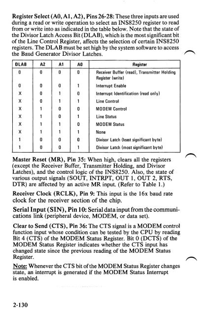
- Page 142 and 143: Asynchronous Communications Adapter
- Page 144 and 145: Modes of Operation The different mo
- Page 146 and 147: I TRANSMIT 'IACUIT I +5V ~ 4S-"l Tx
- Page 150 and 151: Data Set Ready (DSR), Pin 37: When
- Page 152 and 153: Input/Output Signals Data (D7-DO) B
- Page 154 and 155: Bit 3: This bit is the Parity Enabl
- Page 156 and 157: Table 23. BAUD RATE AT 1.843 Mhz De
- Page 158 and 159: Interrupt Identification Register T
- Page 160 and 161: Interrupt Enable Register This 8-bi
- Page 162 and 163: In the diagnostic mode, the receive
- Page 164 and 165: Transmitter Holding Register The T
- Page 166 and 167: Asynchronous Communications Adapter
- Page 168 and 169: SECTION 3. ROM and SYSTEM r", USAGE
- Page 170 and 171: MOV AH,l ;function is to set time o
- Page 172 and 173: Vectors With Special Meanings Inter
- Page 174 and 175: BIOS Memory Map STARTING ADDRESS H
- Page 176 and 177: The timer is set mode 3 which means
- Page 178 and 179: Keyboard Encoding and Usage Encodin
- Page 180 and 181: Keys 71-83 have meaning only in bas
- Page 182 and 183: ALT - Temporarily shifts keys 2-13,
- Page 184 and 185: Keyboard Usage This section is inte
- Page 186 and 187: Table 28. BASIC Screen Editor Speci
- Page 188 and 189: Low Memory Maps (O-'0600'x) Table 3
- Page 190 and 191: BASIC Workspace Variables If you do
- Page 192: APPENDICES Contents: Appendix A: RO
- Page 195 and 196: lOC OBJ LINE SOURCE STITlE( ROM BIO
- Page 197 and 198: LOC OBJ LINE SOURCE 0068 ?! 155 De
- Page 199 and 200:
LOC OBJ LINE SOURCE E09E BBf5 EOAO
- Page 201 and 202:
lOC OBJ LINE SOURCE £179 E2FD 462
- Page 203 and 204:
LOC OBJ LINE SOURCE E278 7408 612 J
- Page 205 and 206:
lOC OBJ LINE SOURCE 755 ; ---------
- Page 207 and 208:
LOC OSJ LINE SOU RCE E42B 7440 900
- Page 209 and 210:
lOC OBJ LINE SOURCE ESIE 884000 E52
- Page 211 and 212:
LaC OBJ LINE SOURCE E613 803E120001
- Page 213 and 214:
LaC OSJ LINE SOURCE E6EC eSOAOE E6E
- Page 215 and 216:
LaC OBJ LINE SOURCE E7SF 1505 .402:
- Page 217 and 218:
LaC OBJ LINE SOURCE 1659 ASSUME CS:
- Page 219 and 220:
LOC OBJ LINE SOURCE E994 8E08 1798
- Page 221 and 222:
LOC 08J LINE SOURCE £"91 474849 EA
- Page 223 and 224:
LaC OBJ LINE SOURCE E890 E99700 E89
- Page 225 and 226:
LOC 08J LINE SOURCE 2255 ;-- INT 13
- Page 227 and 228:
LOC OS! LINE SOURCE 2407 ;------ DI
- Page 229 and 230:
lOC OBJ LINE SOURCE (Eol 7438 fE03
- Page 231 and 232:
LOC OBJ LINE SOURCE Ef'tD £67200 2
- Page 233 and 234:
LOC OBJ LINE SOURCE 2870 I ~- -----
- Page 235 and 236:
LOC (lBJ LINE SOURCE 3007 j --- INT
- Page 237 and 238:
laC OBJ LINE SOURCE 3157 (AH}=6 SCR
- Page 239 and 240:
lOC OBJ LINE SOURt.:E FOA43828ZDOAI
- Page 241 and 242:
lOC OBJ LINE SOURCE FtC7 3458 VIDEO
- Page 243 and 244:
LOC OBJ LINE SOURCE F260 750E f2:62
- Page 245 and 246:
LOC OBJ LINE SOURCE F32B 06 3760 PU
- Page 247 and 248:
LOC OBJ LINE SOURCE F3Cl 3910 NEAR
- Page 249 and 250:
laC OBJ LINE SOURCE 1'460 80HfE F46
- Page 251 and 252:
LOC OBJ LINE SOURCE F4FF BSFB 4213
- Page 253 and 254:
LOC OBJ LINE SOURCE 4359 j------ IM
- Page 255 and 256:
LOC OBJ LINE SOURCE F689 57 4511 PU
- Page 257 and 258:
lOC OBJ LINE SOLIRCE 4662 THE 0 COL
- Page 259 and 260:
LOC OBJ LINE SOURCE F7Cl 8AC4 F7e]
- Page 261 and 262:
LaC OBJ LINE SOURCE F840 4967 EQUIP
- Page 263 and 264:
LOC OBJ LINE SOURCE F8DA E304 5116
- Page 265 and 266:
LOC OBJ LINE SOURCE F97E EBF9 5268
- Page 267 and 268:
LOC OBJ LINE SOURCE H20 C3 5415 RET
- Page 269 and 270:
LOC OBJ LINE SOURCE fC46 0030300000
- Page 271 and 272:
LOC OBJ LINE SOURCE FEBS 833E6E0018
- Page 273 and 274:
lOC OBJ LINE SOURCE 5866 ;.*.-•
- Page 275 and 276:
A-82 NOTES
- Page 277 and 278:
8088 REGISTER MODEL AX: AH Al ACCUM
- Page 279 and 280:
MEMORY SEGMENTATION MODEL LOGICAL
- Page 281 and 282:
XCHG =Exchange RegisterImemory with
- Page 283 and 284:
SBB = Subtract with borrow Reg./mem
- Page 285 and 286:
AND = And Reg./memory and register
- Page 287 and 288:
Indirect within segment 11111111 mo
- Page 289 and 290:
8088 CONDITIONAL TRANSFER OPERATION
- Page 291 and 292:
BOBBINSTRUCTION SET MATRIX LO HI 0
- Page 293 and 294:
INSTRUCTION SET INDEX Mnemonic Pag
- Page 295 and 296:
VALUE AS CHARACTERS AS TEXT ATTRIBU
- Page 297 and 298:
VALUE AS CHARACTERS AS TEXT ATTRIBU
- Page 299 and 300:
VALUE AS CHARACTERS AS TEXT ATTRIBU
- Page 301 and 302:
VALUE AS CHARACTERS AS TEXT ATTRIBU
- Page 303 and 304:
VALUE AS CHARACTERS AS TEXT ATTRIBU
- Page 305 and 306:
Character Set (OO-7F) Quick Referen
- Page 307 and 308:
C-14 NOTES
- Page 309 and 310:
SYSTEM BOARD (PROCESSOR AND SUPPORT
- Page 311 and 312:
SYSTEM BOARD (DEVICE DECODES) I~ i
- Page 313 and 314:
SYSTEM BOARD (ROS AND BUS DRIVER) ~
- Page 315 and 316:
Ṉ-0 SYSTEM BOARD (DYNAMIC MEMORY
- Page 317 and 318:
SYSTEM BOARD (KEYBOARD/SENSE/CONTRO
- Page 319 and 320:
\:j I " m < -tv CI:I Q » :11:1 Q P
- Page 321 and 322:
I- z ..... 0 t:::I 0 ... ;:; ~ r
- Page 323 and 324:
tl I-0'1 ," r-" "~ (S"T" 'RESET I E
- Page 325 and 326:
~ ~ ~ ~ ~~ IBM MONOCHROME DISPLAY A
- Page 327 and 328:
tj III ~ N 14L.517') ~ 0 __________
- Page 329 and 330:
~ N s: N CI CO J ~ CI 2 A Y 18 n DA
- Page 331 and 332:
IBM MONOCHROME OISPLAY DANGER HAZAR
- Page 333 and 334:
COLOR/GRAPHICS MONITOR ADAPTER ~
- Page 335 and 336:
1'. -- COLOR/GRAPHICS MONITOR ADAPT
- Page 337:
1 COLOR/GRAPHICS MONITOR ADAPTER :;
- Page 341 and 342:
PARALLEL PRINTER ADAPTER D-34
- Page 343 and 344:
t:l +AEN AND U'I GATE , ., + ENABL
- Page 345 and 346:
t:! W CI CHARGE PUMP 00 AOI en U ~I
- Page 347 and 348:
5%" DISKETTE DRIVE .., CI -N ... ';
- Page 349 and 350:
t:j ~ N o W z N ;:1'1: ~ aZKO: ." R
- Page 351 and 352:
32KB MEMORY EXPANSION d-w- I NNO) 3
- Page 353 and 354:
64 ~~ MEMORY EXPANSION ~~ D-46
- Page 355 and 356:
BO~ t::l azq +';V[)( +'>vOC 'f c+o;
- Page 357 and 358:
D-50 NOTES
- Page 359 and 360:
IBM Monochrome Display Size: Length
- Page 361 and 362:
12. Binary: (1) Pertaining to a sel
- Page 363 and 364:
40. Hertz (Hz.): A unit offrequency
- Page 365 and 366:
70. OR: A logic operator having the
- Page 367 and 368:
G-8 NOTES
- Page 369 and 370:
Other Related Publications 7. NATIO
- Page 371 and 372:
Asynchronous Communications Adapter
- Page 373 and 374:
Character Codes 3-11 Generator 2-
- Page 375 and 376:
DIN (Connectors) 2-5 DIP (Dual In-L
- Page 377 and 378:
Game Control Adapter (continued) C
- Page 379 and 380:
I/O (Input/Output) Address Map 2-33
- Page 381 and 382:
Microsecond 2-3 Mnemonic B-18 Mod
- Page 383 and 384:
Parameters, 6845 Initialization 2-4
- Page 385 and 386:
Read/Write Memory (continued) Grap
- Page 387 and 388:
s Scan Codes 2-17 Screen 2-43 Sche
- Page 389 and 390:
u Unit Specifications Appendix E
- Page 391 and 392:
1-22 NOTES
- Page 393:
III"I UNITED NO POSTAGE NECESSARY