Project Hurunui Wind Construction and Project Overview
Project Hurunui Wind Construction and Project Overview
Project Hurunui Wind Construction and Project Overview

Create successful ePaper yourself
Turn your PDF publications into a flip-book with our unique Google optimized e-Paper software.
<strong>Project</strong> <strong>Hurunui</strong> <strong>Wind</strong> <strong>Construction</strong> Effects <strong>and</strong> Management Report<br />
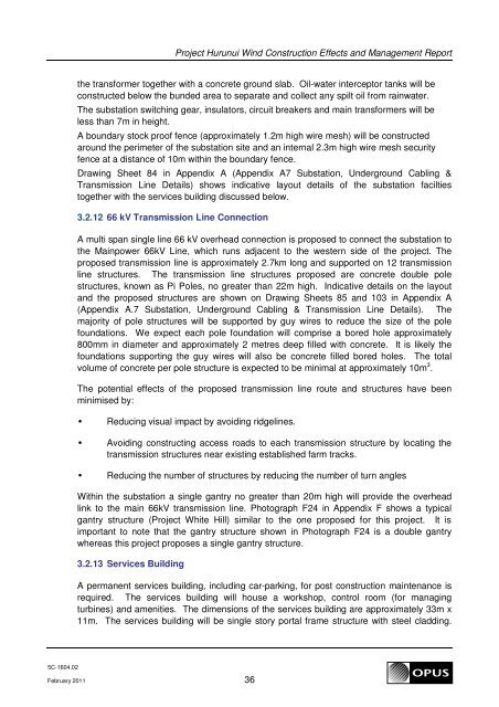
the transformer together with a concrete ground slab. Oil-water interceptor tanks will be<br />
constructed below the bunded area to separate <strong>and</strong> collect any spilt oil from rainwater.<br />
The substation switching gear, insulators, circuit breakers <strong>and</strong> main transformers will be<br />
less than 7m in height.<br />
A boundary stock proof fence (approximately 1.2m high wire mesh) will be constructed<br />
around the perimeter of the substation site <strong>and</strong> an internal 2.3m high wire mesh security<br />
fence at a distance of 10m within the boundary fence.<br />
Drawing Sheet 84 in Appendix A (Appendix A7 Substation, Underground Cabling &<br />
Transmission Line Details) shows indicative layout details of the substation facilties<br />
together with the services building discussed below.<br />
3.2.12 66 kV Transmission Line Connection<br />
A multi span single line 66 kV overhead connection is proposed to connect the substation to<br />
the Mainpower 66kV Line, which runs adjacent to the western side of the project. The<br />
proposed transmission line is approximately 2.7km long <strong>and</strong> supported on 12 transmission<br />
line structures. The transmission line structures proposed are concrete double pole<br />
structures, known as Pi Poles, no greater than 22m high. Indicative details on the layout<br />
<strong>and</strong> the proposed structures are shown on Drawing Sheets 85 <strong>and</strong> 103 in Appendix A<br />
(Appendix A.7 Substation, Underground Cabling & Transmission Line Details). The<br />
majority of pole structures will be supported by guy wires to reduce the size of the pole<br />
foundations. We expect each pole foundation will comprise a bored hole approximately<br />
800mm in diameter <strong>and</strong> approximately 2 metres deep filled with concrete. It is likely the<br />
foundations supporting the guy wires will also be concrete filled bored holes. The total<br />
volume of concrete per pole structure is expected to be minimal at approximately 10m 3 .<br />
The potential effects of the proposed transmission line route <strong>and</strong> structures have been<br />
minimised by:<br />
• Reducing visual impact by avoiding ridgelines.<br />
• Avoiding constructing access roads to each transmission structure by locating the<br />
transmission structures near existing established farm tracks.<br />
• Reducing the number of structures by reducing the number of turn angles<br />
Within the substation a single gantry no greater than 20m high will provide the overhead<br />
link to the main 66kV transmission line. Photograph F24 in Appendix F shows a typical<br />
gantry structure (<strong>Project</strong> White Hill) similar to the one proposed for this project. It is<br />
important to note that the gantry structure shown in Photograph F24 is a double gantry<br />
whereas this project proposes a single gantry structure.<br />
3.2.13 Services Building<br />
A permanent services building, including car-parking, for post construction maintenance is<br />
required. The services building will house a workshop, control room (for managing<br />
turbines) <strong>and</strong> amenities. The dimensions of the services building are approximately 33m x<br />
11m. The services building will be single story portal frame structure with steel cladding.<br />
5C-1604.02<br />
February 2011 36