

ASPIRE Spring 09 - Aspire - The Concrete Bridge Magazine
ASPIRE Spring 09 - Aspire - The Concrete Bridge Magazine
ASPIRE Spring 09 - Aspire - The Concrete Bridge Magazine

You also want an ePaper? Increase the reach of your titles
YUMPU automatically turns print PDFs into web optimized ePapers that Google loves.
Tse, Pilarski, Amundson and Molnau<br />
2007 NBC<br />
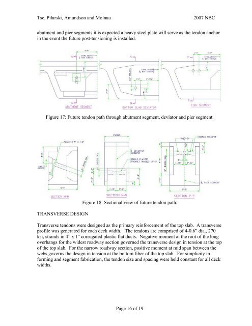
abutment and pier segments it is expected a heavy steel plate will serve as the tendon anchor<br />
in the event the future post-tensioning is installed.<br />
Figure 17: Future tendon path through abutment segment, deviator and pier segment.<br />
TRANSVERSE DESIGN<br />
Figure 18: Sectional view of future tendon path.<br />
Transverse tendons were designed as the primary reinforcement of the top slab. A transverse<br />
profile was generated for each deck width. <strong>The</strong> tendons are comprised of 4-0.6” dia., 270<br />
ksi, strands in 4” x 1” corrugated plastic flat ducts. Negative moment at the root of the long<br />
overhangs for the widest roadway section governed the transverse design in tension at the top<br />
of the top slab. For the narrow roadway section, positive moment at mid span between the<br />
webs governs the design in tension at the bottom fiber of the top slab. For simplicity in<br />
forming and segment fabrication, the tendon size and spacing were held constant for all deck<br />
widths.<br />
Page 16 of 19


