626 TRANSACTIONS OF TH E A.S.M.E. OCTOBER, 1941Such data would be of help in verifying the results of theoreticalstudies.C. S. L. R o b i n s o n . 21 The authors have confirmed the factthat the quantity of oil supplied to a bearing affects the powerlosses. It might be pointed out, however, that an analysis ofthe results can be made in terms of dimensionless groups.Retaining the original nomenclature, assume L = (Q, p, Z,N, d, I, c).The specific weight of the oil is not included. This assumesthat not much work is done in lifting the oil from a lower levelto a higher one, and that the kinetic energy of the oil is notpaper because of a similar experience of testing a high-speedbearing which was described in a previous paper.26Under the heading, “Effect of Top-Half Grooving on Loss,”there is a statement which, if substantiated, seems of importance.It is: “The effect on the power loss was not measurable in,thesetests, the reason for this being that a vacuum occurs over alarge portion of the upper half.” Did the authors measure thisvacuum and if so what figures have they obtained? The lossesin the upper half which is not carrying any load must not be overlookedespecially if the width of the upper shell groove is 2/ 3 thatof the bearing length, as mentioned in the paper. In an endeavorto segregate the upper-half and relief losses from the lower-partlosses, the following was done in the case of the 7 X lO’/Vin.bearing under 202 psi pressure at 3600 rpm :For various oil viscosities and a flow of oil of 7.5 gpm the losseswere calculated separately for the two 90-deg reliefs, the upperhalf and the lower half.27 The average relief clearance wasF i g . 15 C o e f f i c i e n t o f F r i c t i o n f o r S q u a r e B e a r i n g s (l/d = 1)f o r L a r g e s t a n d S m a l l e s t V a l u e s o f Q/Nd3 T e s t e dimportant. There may be energy expended in pumping oilagainst a pressure change, but this depends upon the volume,not the weight, of oil flow. This precludes the possibility of aReynolds number criterion.Applying the pi theorem of dimensional analysisThe new dimensionless group22 Q/Nd3, might be called the“specific oil flow” or the “specific quantity of oil.” It is interestingto compare it with the dimensionless source strength used byMuskat and Morgan23•furthermore, the test results obtained by the authors areconsistent with those given by Muskat and Morgan, where(r/c)/ was plotted against (r/c)2 ZN/p for various values of go.The accompanying curve Fig. 15 shows the approximate magnitudeof the effect of Q/Nd3 on the coefficient of friction. Thisis based on some of the authors’ original data for a 3 X 3-in.bearing and a 4 X 4-in. bearing.The writer is indebted to the authors for permitting the useof their results in the foregoing discussion.L. M. T i c h v i n s k y . 25 The writer is greatly interested in this21 Gear Engineering D epartm ent, General Electric Company,River Works, W est Lynn, Mass. Mem. A.S.M.E.22 Reference (4) of paper, p. 84.23 “The Thick-Film Lubrication of Full Journal Bearings of FiniteW idth,” by M. M uskat and F. Morgan. Trans. A.S.M .E., vol, 61,1939, p. A-117.24 The units of ZN/p are centipoises X rpm /psi; and those ofQ/Nd3 are gpm /rpm X (in.)3.26 U. S. Naval Engineering Experiment Station, Annapolis, Md.F i g . 16 D is t r ib u t io n o f L o s s e s in a 7 X IO '/V I n . H ig h -S p e e d B e a r in g(Z = [15 — 22] centipoises; N = 3600 rpm ; P = 202 psi; Q — 7.5 gpm.)taken from the bearing drawing. The clearance in the upperhalf was calculated by figuring the minimum oil-film thicknessin the lower half and subtracting it from the total diametralclearance. On the curve, Fig. 16 of this discussion, the totalcalculated losses, composed of losses in reliefs, upper half andlower half are compared with losses measured during tests. Itis seen that the difference between the measured and calculatedlosses is greater for higher values of ZN/P. The individuallosses also increase with speed. In the case of the bearing tested,the calculated losses in the upper half and in the reliefs representeach about 20 per cent of the total losses so that the losses in thelower half amount to 60 per cent of the total bearing losses.26 “Tests of a 7 by lOVi-Inch Bearing a t 3600 Rpm ,” by L. M.Tichvinsky, Trans. A.S.M.E., vol. 60, 1938, pp. 393-397.27 For the m ethod of calculation refer to: “Journal Bearing Performance,”by R. Baudry and L. M. Tichvinsky, Trans. A.S.M.E.,vol. 57, 1935, p. A-121.
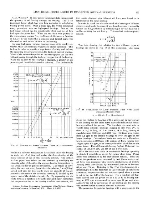
LINN, IRONS—POWER LOSSES IN HIGH-SPEED JOURNAL BEARINGS 627C. D. W i l s o n . 28 In their paper, the authors take into accountthe quantity of oil flowing through the bearing. This is animportant factor which has been long neglected in calculatingbearing power losses. Over 2 years ago, the writer conductedmany power-loss tests on high-speed bearings. One of thefirst things noticed was the considerable effect that the oil flowhad upon the power loss. When the test data were plotted inthe conventional manner (i.e., coefficient of friction as a functionof ZN/p), it was found that a separate and distinct curve wasobtained for each rate of oil flow to the bearing.In large high-speed turbine bearings, more oil is usually circulatedthan the minimum required for stable operation. Thisis done in order to provide a large factor of safety and to keepthe operating temperatures within the limits of current practice.Much of the excess oil supplied to the bearing spills out the endswithout passing through the load-carrying portion of the bearing.When the oil flow to the bearing is changed, a greater or lesspercentage of the oil is by-passed in this way. This undoubtedlytest results obtained with different oil flows were found to beconsistent for the same bearing.In order to check test data obtained with bearings of differentdiameters and loads, however, it was found necessary to modifyfurther the ZN/p relation by multiplying it by the diameter dand by omitting the unit load p. This resulted in the empiricalrelationTest data showing this relation for two different types ofbearings are shown in Fig. 17 of this discussion. One curveF ig . 17R e s u l t s o f A l l i s - C h a l m e b s T e s t s o n 23 D i f f e r e n tB e a r i n g sresults in a different temperature distribution inside the bearingfor each rate of oil flow and makes the determination of themean viscosity of the oil film extremely difficult. The authorsin their paper have taken this into account by modifying theviscosity value of the oil at the average bearing temperature bythe actual oil flow in gallons per minute. The writer, in correlatinghis own test data, found that the relation / = {ZN/p)agreed well with the test results when the viscosity Z was expressedas the ratio of the oil-outlet viscosity Zi divided by thesquare root of the oil-inlet viscosity Z2. By expressing the viscosityterm as a function of both the inlet and outlet viscosities,the temperature rise in the bearing is taken into account, and28 Steam Turbine Engineering D epartm ent, Allis-Chalmers M anufacturingCompany, Milwaukee, Wis. Mem. A.S.M.E.shows the relation for bearings with a groove cut in the top halfof the bearing and the other curve shows the relation for similarbearings without the groove. The test data represent tests ontwenty-three different bearings, ranging in size from 2V2 in.diam X 3V2 in. long, to 17 in. diam X 18 in. long, running atspeeds between 1500 rpm and 8000 rpm. Oil flows were variedfrom 1.2 gpm in the smaller bearings to over 100 gpm in thelarger bearings. One series of tests was made on a 12-in-diambearing running at 3600 rpm with various oil flows, ranging from16 gpm up to 100 gpm, so as to study the effect of oil flow on thepower losses. Four different oils having Saybolt Universal viscositiesof 150, 210, 350, and 560 at 100 F were used.All of the tests were made on commercial bearings operatingin standard pedestals as set up for regular shop tests. Powerlosses were determined by the heat-balance method. Inlet andoutlet temperatures were measured by test thermometers andoil flows were measured with positive-displacement oil meters.Bearing loads were limited by commercial practice to between60 psi and 175 psi. Referring to Fig. 17 of this discussion, it isinteresting to note the reduction in the coefficient of friction fora constant temperature rise and constant speed when a grooveis cut in the top half of the bearing. For a constant oil flow,tests showed that the power loss in a 12 X 12 in. bearing runningat 3600 rpm was reduced by more than 20 per cent whena groove was cut in the top half of the bearing and the bearingwas retested under otherwise identical conditions.The power-loss formula for bearings with a groove cut in the
- Page 1 and 2:
Transactionsof theHeat Transfer to
- Page 3 and 4:
H eat T ran sfer to H ydrogen-N itr
- Page 5 and 6:
COLBURN, COGHLAN—HEAT TRANSFER TO
- Page 7 and 8:
COLBURN, COGHLAN—HEAT TRANSFER TO
- Page 9 and 10:
Electric-Slip Couplings for UseW it
- Page 11 and 12:
ANDRIOLA—ELECTRIC-SLIP COUPLINGS
- Page 13 and 14:
ANDRIOLA—ELECTRIC-SLIP COUPLINGS
- Page 15 and 16: ANDRIOLA—ELECTRIC-SLIP COUPLINGS
- Page 17 and 18: ANDRIOLA—ELECTRIC-SLIP COUPLINGS
- Page 19 and 20: Flexible Couplings for Internal-C o
- Page 21 and 22: ORMONDROYD—FLEXIBLE COUPLINGS FOR
- Page 23 and 24: ORMONDROYD—FLEXIBLE COUPLINGS FOR
- Page 25 and 26: C om bustion Explosions in P ressur
- Page 27 and 28: CREECH—COMBUSTION EXPLOSIONS IN P
- Page 29 and 30: CREECH—COMBUSTION EXPLOSIONS IN P
- Page 31 and 32: M athem atics of Surge Vessels and
- Page 33 and 34: MASON, PHILBRICK—MATHEMATICS OF S
- Page 35 and 36: MASON, PHILBRICK—MATHEMATICS OF S
- Page 37 and 38: MASON, PHILBRICK—MATHEMATICS OF S
- Page 39 and 40: MASON, PHILBRICK—MATHEMATICS OF S
- Page 41 and 42: MASON, PHILBRICK—MATHEMATICS OF S
- Page 43 and 44: MASON, PHILBRICK—MATHEMATICS OF S
- Page 45 and 46: 604 TRANSACTIONS OF THE A.S.M.E. OC
- Page 47 and 48: 606 TRANSACTIONS OF THE A.S.M.E. OC
- Page 49 and 50: 608 TRANSACTIONS OF THE A.S.M.E. OC
- Page 51 and 52: 610 TRANSACTIONS OF THE A.S.M.E. OC
- Page 53 and 54: TRANSACTIONS OF THE A.S.M.E. OCTOBE
- Page 55 and 56: 614 TRANSACTIONS OF THE A.S.M.E. OC
- Page 58 and 59: 618 TRANSACTIONS OF THE A.S.M.E. OC
- Page 60 and 61: 620 TRANSACTIONS OF THE A.S.M.E. OC
- Page 62 and 63: 622 TRANSACTIONS OF THE A.S.M.E. OC
- Page 64 and 65: 624 TRANSACTIONS OF THE A.S.M.E. OC
- Page 68 and 69: 628 TRANSACTIONS OF THE A.S.M.E. OC
- Page 70 and 71: Flow P roperties of L ubricantsU nd
- Page 72 and 73: NORTON, KNOTT, MUENGER—FLOW PROPE
- Page 74 and 75: NORTON, KNOTT, MUENGER—FLOW PROPE
- Page 76 and 77: NORTON, KNOTT, MUENGER—FLOW PROPE
- Page 78 and 79: NORTON, KNOTT, MUENGER—FLOW PROPE
- Page 80 and 81: NORTON, KNOTT, MUENGER—FLOW PROPE
- Page 82 and 83: NORTON, KNOTT, MUENGER—FLOW PROPE
- Page 84 and 85: 646 TRANSACTIONS OF THE A.S.M.E. OC
- Page 86 and 87: 648 TRANSACTIONS OF THE A.S.M.E. OC
- Page 88 and 89: 650 TRANSACTIONS OF THE A.S.M.E. OC
- Page 90 and 91: 652 TRANSACTIONS OF THE A.S.M.E. OC
- Page 92 and 93: A H igh-T em perature Bolting M ate
- Page 94 and 95: WHEELER—A HIGH-TEMPERATURE BOLTIN
- Page 96 and 97: WHEELER—A HIGH-TEM PERATURE BOLTI
- Page 98 and 99: WHEELER—A HIGH-TEM PERATURE BOLTI
- Page 100 and 101: WHEELER—A HIGH-TEMPERATURE BOLTIN
- Page 102 and 103: WHEELER—A HIGH-TEMPERATURE BOLTIN
- Page 104 and 105: W HEELER—A HIGH-TEMPERATURE BOLTI