650 TRANSACTIONS OF THE A.S.M.E. OCTOBER, 1941authors in this investigation were not referred to a standardtemperature.)Although the authors do not use the ammonia correctionsmentioned in the introduction to their paper, it should be pointedout that the value assumed by them is higher than experimentallydetermined values found by Rummel and by Schwartz.Rummel15 found 7.3 micromhos per ppm nitrogen ammonia forammonia alone in water, and 8 micrornhos per ppm nitrogenammonia for carbonated-ammonia solution. Schwartz16 reported8 micromhos per ppm nitrogen ammonia.Nomenclature. It is observed that the terms “total dissolvedsolids,” “total solids,” and “dissolved solids” appear to be usedinterchangeably throughout the paper. The following definitions17on water for industrial use are given by the AmericanSociety for Testing Materials:2 (e) Dissolved Solids.11 “Dissolved solids” comprise thedried residue from evaporation of the filtrate, after separation ofsuspended solids.2 (/) Dissolved Salts. “Dissolved salts” are the sum of theindividually determined ions in a complete analysis.The terms “dissolved solids” and “dissolved salts” are appropriatefor use and applicable to the subject m atter discussed bythe authors.A. E. Kin'REDOE.1* Preceding a broad discussion of steamsamplingequipment the writer wishes to commend the authorson the compact and effective mechanical design of the equipmentthey had described, in the light of the purpose for which thisequipment was developed. Reference to the field of applicationfor which this equipment is designed is purposely made becausethere is a fair distinction to be made between equipmentdesigned to serve the single function of degasifying the steamsample for conductivity test and that for the dual function ofboth degasifying the steam sample for conductivity tests whileyet permitting the collection of the separated gas for analysis.An appreciable demand for equipment of the latter type seemsto be indicated by the need for detecting quickly the generationof hydrogen in high-pressure boilers and superheaters, resultingfrom the dissociation of steam; appearance of hydrogen in thesample, of course, indicating a dissociation and active corrosionby the free oxygen so liberated.It seems impossible to discuss a paper of this kind technicallywithout first establishing a few points of fundamental fact. Inany physical process of gas removal there is no possible designwhich can produce an absolute zero in fact. Different designsemphasize different advantages but, in such a process, dependingupon a driving force between the solvent and the solute, the endpoint must, from the nature of the process, still have an actualif not measurable difference between the actual value, whethermeasurable or not, and absolute zero. Appreciation of this factis necessary to give proper evaluation to the different methodsof design of degasifying equipment. This paper emphasizes theuse of clean steam for flushing the fractionating tower and acounterflow arrangement of the condensed sample and the flushingsteam. Both of these elements are in themselves desirablefeatures if they can be utilized without sacrifice of other desir16 D ata from curve prepared by J. K. Rummel and availablethrough the courtesy of The Babcock & Wilcox Company, NewYork, N. Y.le Footnote 13 of this discussion, refer to p. 729.17 “ Tentative M ethods of Reporting Results of Analysis of IndustrialW aters,” D596-40T A.S.T.M . Book of Standards, Supplement1940, p art 2, p. 541.18 The term “ total dissolved solids” is not defined on pp. 56 and92 of Bibliography (4), but what appears to be an ambiguous definitionappears on page 151.18 Chief Engineer, Cochrane Corporatien, Philadelphia, Pa.able features. The point we wish to make is that proper evaluationof all the elements entering into the degasifying process arenecessary to determine the best cycle of operation for any particularequipment.There are three basic factors to be considered in the design ofdegasifying equipment. These are:1 The creation of a satisfactory equilibrium condition.2 The selection of an advantageous operating temperature.3 The provision of an effective degasifying means.Equipments, designed to operate at relatively high vacuumsand temperatures below 100 F, very easily produce satisfactoryequilibrium conditions but are greatly handicapped by thehigher viscosities of water at these temperatures. The higherviscosity of the water places a greater burden on the deaeratingmeans in spite of the favorable equilibrium conditions. Degasificationat low temperatures can be accomplished but operatesunder a definite handicap.Operation of degasifying equipment at around atmosphericpressure with counterflow of steam and water provides a suitableequilibrium condition and utilizes the advantageously low viscosityof water at this temperature. In spite of the favorableequilibrium condition and operating temperature, the controllinglimitation on the design of degasifying equipment for atmosphericoperation will be the actual degasifying means. The latter isvery apt to be handicapped and compromised in the design ofsmall compact test equipment such as that under discussion.Because the limiting factor in the design of degasifying equipmentis the third element of the three tabulated, the design ofequipment of the writer’s company to be later described, utilizesthe most effective degasifying means known, i.e., the atomizingmethod, at a very slight sacrifice to the most favorable equilibriumcondition for the purpose of obtaining the greatest neteffective result.If a condensed-steam sample, containing as much as 1 cc per 1of oxygen is flushed with an equal quantity of steam at atmosphericpressure in an open chamber without a counterflow arrangement,all but 1 part in 100,000 of the dissolved gas in theliquid would be transferred to the steam, if equilibrium werereached. That is to say, when the quantity of flushing steamequals the quantity of condensate to be deaerated and the steamitself contains 1 cc per 1 of oxygen, the presence of that oxygenwould support in solution in the liquid only 0.00001 cc per 1.This value ranges somewhere between 0.2 and 1 per cent of thesmallest quantity of oxygen that can be determined by any knowntest method. It emphasizes the fallacy of limiting equipmentdesign to conditions which are theoretically advantageous butpractically worthless. For the same reason, we choose to placeemphasis, in the design of our equipment, on effective means ofdegasification. Similar values apply to other gases, proportionateto their solubility and inversely proportionate to their specificvolume at the operating conditions.In contrast to the equipment presented by the authors, wewish to refer to equipment designed by the writer’s company toserve all the purposes of the former equipment and, in addition,to make possible selection of gases removed from the steamsample for analysis. In the foregoing, we have briefly outlinedreasons for placing emphasis on the effectiveness of the deaeratingmeans as opposed to the obvious need of giving attention tosatisfactory equilibrium conditions. In the degasification of asteam sample, involving the removal of carbon dioxide and ammonia,there is additional reason to use the most effective meansof degasification possible.Solutions of both carbon dioxide in water and ammonia inwater form loose chemical combinations of carbonic acid andammonium hydroxide respectively. Each also ionizes the solu-
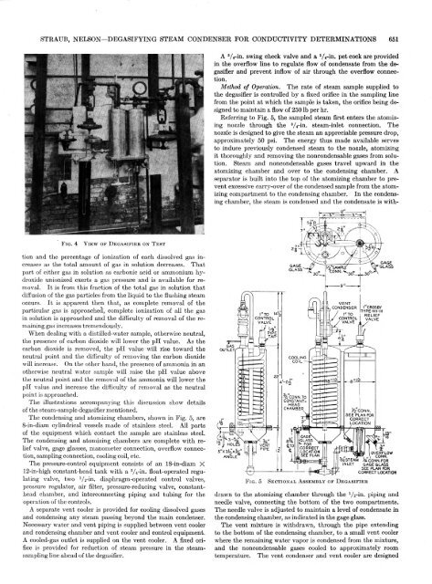
STRAUB, NELSON—DEGASIFYING STEAM CONDENSER FOR CONDUCTIVITY DETERMINATIONS 651A 3/ 4-in. swing check valve and a 'A-in. pet cock are providedin the overflow line to regulate flow of condensate from the degasifierand prevent inflow of air through the overflow connection.Method of Operation. The rate of steam sample supplied tothe degasifier is controlled by a fixed orifice in the sampling linefrom the point at which the sample is taken, the orifice being designedto maintain a flow of 250 lb per hr.Referring to Fig. 5, the sampled steam first enters the atomizingnozzle through the 3A-in. steam-inlet connection. Thenozzle is designed to give the steam an appreciable pressure drop,approximately 50 psi. The energy thus made available servesto induce previously condensed steam to the nozzle, atomizingit thoroughly and removing the noncondensable gases from solution.Steam and noncondensable gases travel upward in theatomizing chamber and over to the condensing chamber. Aseparator is built into the top of the atomizing chamber to preventexcessive carry-over of the condensed sample from the atomizingcompartment to the condensing chamber. In the condensingchamber, the steam is condensed and the condensate is withF ig . 4V ie w o f D e g a s i f i e r o n T e s ttion and the percentage of ionization of each dissolved gas increasesas the total amount of gas in solution decreases. Thatpart of either gas in solution as carbonic acid or ammonium hydroxideunionized exerts a gas pressure and is available for removal.It is from this fraction of the total gas in solution thatdiffusion of the gas particles from the liquid to the flushing steamoccurs. It is apparent then that, as complete removal of theparticular gas is approached, complete ionization of all the gasin solution is approached and the difficulty of removal of the remaininggas increases tremendously.When dealing with a distilled-water sample, otherwise neutral,the presence of carbon dioxide will lower the pH value. As thecarbon dioxide is removed, the pH value will rise toward theneutral point and the difficulty of removing the carbon dioxidewill increase. On the other hand, the presence of ammonia in anotherwise neutral water sample will raise the pH value abovethe neutral point and the removal of the ammonia will lower thepH value and increase the difficulty of removal as the neutralpoint is approached.The illustrations accompanying this discussion show detailsof the steam-sample degasifier mentioned.The condensing and atomizing chambers, shown in Fig. 5, are8-in-diam cylindrical vessels made of stainless steel. All partsof the equipment which contact the sample are stainless steel.The condensing and atomizing chambers are complete with reliefvalve, gage glasses, manometer connection, overflow connection,sampling connection, cooling coil, etc.The pressure-control equipment consists of an 18-in-diam X12-in-high constant-head tank with a V-rin. float-operated regulatingvalve, two 'A-in. diaphragm-operated control valves,pressure regulator, air filter, pressure-reducing valve, constantheadchamber, and interconnecting piping and tubing for theoperation of the controls.A separate vent cooler is provided for cooling dissolved gasesand condensing any steam passing beyond the main condenser.Necessary water and vent piping is supplied between vent coolerand condensing chamber and vent cooler and control equipment.A cooled-gas outlet is supplied on the vent cooler. A fixed orificeis provided for reduction of steam pressure in the steamsamplingline ahead of the degasifier.drawn to the atomizing chamber through the V2-in. piping andneedle valve, connecting the bottom of the two compartments.The needle valve is adjusted to maintain a level of condensate inthe condensing chamber, as indicated in the gage glass.The vent mixture is withdrawn, through the pipe extendingto the bottom of the condensing chamber, to a small vent coolerwhere the remaining water vapor is condensed from the mixture,and the noncondensable gases cooled to approximately roomtemperature. The vent condenser and vent cooler are designed
- Page 1 and 2:
Transactionsof theHeat Transfer to
- Page 3 and 4:
H eat T ran sfer to H ydrogen-N itr
- Page 5 and 6:
COLBURN, COGHLAN—HEAT TRANSFER TO
- Page 7 and 8:
COLBURN, COGHLAN—HEAT TRANSFER TO
- Page 9 and 10:
Electric-Slip Couplings for UseW it
- Page 11 and 12:
ANDRIOLA—ELECTRIC-SLIP COUPLINGS
- Page 13 and 14:
ANDRIOLA—ELECTRIC-SLIP COUPLINGS
- Page 15 and 16:
ANDRIOLA—ELECTRIC-SLIP COUPLINGS
- Page 17 and 18:
ANDRIOLA—ELECTRIC-SLIP COUPLINGS
- Page 19 and 20:
Flexible Couplings for Internal-C o
- Page 21 and 22:
ORMONDROYD—FLEXIBLE COUPLINGS FOR
- Page 23 and 24:
ORMONDROYD—FLEXIBLE COUPLINGS FOR
- Page 25 and 26:
C om bustion Explosions in P ressur
- Page 27 and 28:
CREECH—COMBUSTION EXPLOSIONS IN P
- Page 29 and 30:
CREECH—COMBUSTION EXPLOSIONS IN P
- Page 31 and 32:
M athem atics of Surge Vessels and
- Page 33 and 34:
MASON, PHILBRICK—MATHEMATICS OF S
- Page 35 and 36:
MASON, PHILBRICK—MATHEMATICS OF S
- Page 37 and 38: MASON, PHILBRICK—MATHEMATICS OF S
- Page 39 and 40: MASON, PHILBRICK—MATHEMATICS OF S
- Page 41 and 42: MASON, PHILBRICK—MATHEMATICS OF S
- Page 43 and 44: MASON, PHILBRICK—MATHEMATICS OF S
- Page 45 and 46: 604 TRANSACTIONS OF THE A.S.M.E. OC
- Page 47 and 48: 606 TRANSACTIONS OF THE A.S.M.E. OC
- Page 49 and 50: 608 TRANSACTIONS OF THE A.S.M.E. OC
- Page 51 and 52: 610 TRANSACTIONS OF THE A.S.M.E. OC
- Page 53 and 54: TRANSACTIONS OF THE A.S.M.E. OCTOBE
- Page 55 and 56: 614 TRANSACTIONS OF THE A.S.M.E. OC
- Page 58 and 59: 618 TRANSACTIONS OF THE A.S.M.E. OC
- Page 60 and 61: 620 TRANSACTIONS OF THE A.S.M.E. OC
- Page 62 and 63: 622 TRANSACTIONS OF THE A.S.M.E. OC
- Page 64 and 65: 624 TRANSACTIONS OF THE A.S.M.E. OC
- Page 66 and 67: 626 TRANSACTIONS OF TH E A.S.M.E. O
- Page 68 and 69: 628 TRANSACTIONS OF THE A.S.M.E. OC
- Page 70 and 71: Flow P roperties of L ubricantsU nd
- Page 72 and 73: NORTON, KNOTT, MUENGER—FLOW PROPE
- Page 74 and 75: NORTON, KNOTT, MUENGER—FLOW PROPE
- Page 76 and 77: NORTON, KNOTT, MUENGER—FLOW PROPE
- Page 78 and 79: NORTON, KNOTT, MUENGER—FLOW PROPE
- Page 80 and 81: NORTON, KNOTT, MUENGER—FLOW PROPE
- Page 82 and 83: NORTON, KNOTT, MUENGER—FLOW PROPE
- Page 84 and 85: 646 TRANSACTIONS OF THE A.S.M.E. OC
- Page 86 and 87: 648 TRANSACTIONS OF THE A.S.M.E. OC
- Page 90 and 91: 652 TRANSACTIONS OF THE A.S.M.E. OC
- Page 92 and 93: A H igh-T em perature Bolting M ate
- Page 94 and 95: WHEELER—A HIGH-TEMPERATURE BOLTIN
- Page 96 and 97: WHEELER—A HIGH-TEM PERATURE BOLTI
- Page 98 and 99: WHEELER—A HIGH-TEM PERATURE BOLTI
- Page 100 and 101: WHEELER—A HIGH-TEMPERATURE BOLTIN
- Page 102 and 103: WHEELER—A HIGH-TEMPERATURE BOLTIN
- Page 104 and 105: W HEELER—A HIGH-TEMPERATURE BOLTI