software training courses 2010 corsi di addestramento ... - EnginSoft
software training courses 2010 corsi di addestramento ... - EnginSoft
software training courses 2010 corsi di addestramento ... - EnginSoft

You also want an ePaper? Increase the reach of your titles
YUMPU automatically turns print PDFs into web optimized ePapers that Google loves.
Thermal performance<br />
The thermal performances of the <strong>di</strong>fferent configurations<br />
proposed are stu<strong>di</strong>ed with steady-state 2D simulations. Heat<br />
flux is applied while the BC is the temperature setting of the<br />
cooling pipes inner surface. We collected the resulting max<br />
ΔT across the staves in a table, using a performance<br />
parameter obtained by <strong>di</strong>vi<strong>di</strong>ng ΔT by the thermal power flux<br />
imposed as load.<br />
Evaluation of the thermal expansion coefficients<br />
Longitu<strong>di</strong>nal CTE is calculated for the possible<br />
configurations; the simulations are executed with the volume<br />
fiber percentage measured on the samples, ranging from 30%<br />
to 60%. The calculation procedure is to build a model and<br />
increase the nodal temperature in order to have a ΔT: the<br />
nodal <strong>di</strong>splacement is evaluated and the relative CTE is then<br />
calculated. ESAComp has been used for cross check.<br />
Pressurized pipe lay-up optimization<br />
The design of the pipe laminate should satisfy these criteria:<br />
withstan<strong>di</strong>ng a pressure test of 15 MPa, having a safety<br />
factor of 4 on the design pressure against a Tsai-Hill failure<br />
criterion, matching the longitu<strong>di</strong>nal CTE of the other<br />
materials, remaining tight under pressure with maximum<br />
transversal ply strain ≤ 0.1%. This is the parameter that<br />
controls the micro-cracks growth. Pipe is modelled using the<br />
element layered-type Solid186. Pressurized vessel con<strong>di</strong>tions<br />
are simulated with axial force on the pipe extremities.<br />
Different pipe stacking sequences are considered for these<br />
structural simulations; for each ply longitu<strong>di</strong>nal, transversal<br />
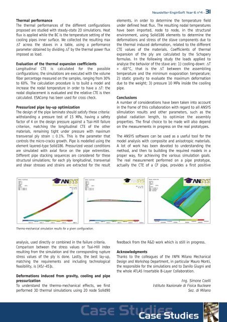
and shear stresses and strains are extracted for the result<br />
Thermo-mechanical simulation results for a given configuration.<br />
analysis, used <strong>di</strong>rectly or combined in the failure criteria.<br />
Comparison between the stress values or Tsai-Hill index<br />
resulting from the simulation and the correspon<strong>di</strong>ng rupture<br />
stress values of the ply is done. Lastly, the best lay-up,<br />
matching the requirements and inclu<strong>di</strong>ng technological<br />
feasibility, is [45/-45]s.<br />
Deformations induced from gravity, cooling and pipe<br />
pressurization<br />
To understand the thermo-mechanical effects, we first<br />
performed 3D thermal simulations using 20 node Solid90<br />
Newsletter <strong>EnginSoft</strong> Year 6 n°4 - 31<br />
elements, in order to determine the temperature field<br />
under defined heat flux. The resulting nodal temperatures<br />
have been imported, node to node, in the structural<br />
environment, using Solid186 elements to determine the<br />
deformations and stress of the stave components due to<br />
the thermal induced deformation, related to the <strong>di</strong>fferent<br />
CTE values of the materials. Coefficients of thermal<br />
expansion of the ply are calculated by the Schapery<br />
formulas. In the following study the loads applied to<br />
analyse the behavior of the stave are: 1) cooling-down: ΔT<br />
= -60°C, that is the ΔT between the assembling<br />
temperature and the minimum evaporation temperature;<br />
2) static gravity to evaluate the maximum deformation<br />
due to the weight; 3) pressure 10 MPa inside the cooling<br />
pipe.<br />
Conclusions<br />
A number of considerations have been taken into account<br />
in the frame of this collaboration with regard to all ANSYS<br />
silmulation results and other parameters, such as the<br />
global ra<strong>di</strong>ation length, to optimize the assembly<br />
properties. The final choice to be made will also depend<br />
on the measurements in progress on the real prototypes.<br />
The ANSYS <strong>software</strong> can be used as a useful tool for the<br />
model analysis with composite and anisotropic materials.<br />
A lot of work has been devoted to understan<strong>di</strong>ng the<br />
method, and then to buil<strong>di</strong>ng the required models in a<br />
proper way, for achieving the various simulation goals.<br />
The real measurement performed on a pipe prototype,<br />
actually the CTE of a CF pipe, provides a first positive<br />
feedback from the R&D work which is still in progress.<br />
Acknowledgments<br />
Thanks to the colleagues of the INFN Milano Mechanical<br />
Design and Workshop Department, in particular Mauro Monti,<br />
the responsible for the simulations and to Danilo Giugni and<br />
the whole ATLAS Insertable B-Layer Collaboration.<br />
Ing. Simone Coelli<br />
Istituto Nazionale <strong>di</strong> Fisica Nucleare<br />
Sez. <strong>di</strong> Milano