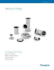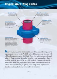
Couplings - Eoss.com
Couplings - Eoss.com
Couplings - Eoss.com

You also want an ePaper? Increase the reach of your titles
YUMPU automatically turns print PDFs into web optimized ePapers that Google loves.
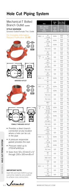
Pipe PreparationSECTION 15: PIPE PREPARATIONGroove DimensionsSTANDARD CUT GROOVESPECIFICATIONS NOTESFor Complete InformationRequest Publication 25.01ODBAExaggerated for ClarityGROOVE DIMENSION NOTES:Column 1: Nominal Pipe SizeColumn 2: Outside DiameterThe outside diameter of cut grooved pipeshall not vary more than the tolerancelisted. For carbon steel pipe the maximumallowable tolerance from square cut endsto 0.76 mm/0.030" for 20 – 90 mm/¾ – 3½";1.14 mm/0.045" for 100 – 150 mm/4 – 6";and 1.5 mm/0.060" for sizes 200 mm/8" O.D.and above measured from true square line.Column 3: Gasket SeatThe pipe surface shall be free fromindentations, roll marks, and projectionsfrom the end of the pipe to the groove,to provide a leak-tight seal for the gasket.All loose paint, scale, dirt, chips, greaseand rust must be removed. It continuesto be Victaulic’s first re<strong>com</strong>mendationthat pipe be square cut. When usingbeveled pipe contact Victaulic for details.Square cut pipe must be used withFlushSeal and EndSeal gaskets. Gasket seat“A” is measured from the end of the pipe.Column 4: Groove WidthThe bottom of groove to be free ofloose dirt, chips, rust and scale that mayinterfere with proper coupling assembly.Maximum permissible radius at bottomof groove is 3.8 mm/.015".Column 5: Groove Outside DiameterThe groove must be of uniform depthfor the entire pipe circumference. Groovemust be maintained within the “C”diameter tolerance listed.Column 6: Groove DepthFor reference only. Groove must conformto the groove diameter “C” listed.Column 7: Minimum AllowableWall ThicknessThis is the minimum wall thicknesswhich may be cut grooved.BCDTSTANDARD CUT GROOVE SPECIFICATIONS – STEEL AND OTHER METALLIC PIPE @1 2 3 4 5 6 7NominalSizemmInchesPipe Outside Diameter O.D.AGasket Seat± 0.76± 0.03Dimensions – mm/InchesBGrv. Width± 0.76CGroove DiameterBasic Maximum Minimum ± 0.03 Maximum MinimumTABLE CONTINUED FROM PG. 15-22GrooveDepthDref.TMin. Allow.WallThickness355.6 355.6 357.2 354.8 23.83 12.70 350.0 349.3 2.77 7.1414 14.000 14.063 13.969 0.938 0.500 13.781 13.751 0.109 0.281377.0 mm377.0 379.4 376.2 23.83 12.70 371.1 370.4 2.94 8.0014.843 14.937 14.811 0.938 0.500 14.611 14.581 0.116 0.31515"381.0 382.6 380.2 23.83 12.70 375.4 374.7 2.77 7.9215.000 15.063 14.969 0.938 0.500 14.781 14.751 0.109 0.312406.4 406.4 408.0 405.6 23.83 12.70 400.8 400.1 2.77 7.9216 16.000 16.063 15.969 0.938 0.500 15.781 15.751 0.109 0.312426.0 mm426.0 428.4 425.2 23.83 12.70 419.5 418.6 3.28 8.5116.772 16.866 16.740 0.938 0.500 16.514 16.479 0.129 0.335457.0 457.0 458.8 456.4 25.40 12.70 451.6 450.9 2.77 7.9218 18.000 18.063 17.969 1.000 0.500 17.781 17.751 0.109 0.312480.0mm480.0 482.4 479.1 25.40 12.70 473.1 472.2 3.45 8.9918.898 18.992 18.863 1.000 0.500 18.626 18.591 0.136 0.354508.0 508.0 509.6 507.2 25.40 12.70 502.4 501.7 2.77 7.9220 20.000 20.063 19.969 1.000 0.500 19.781 19.751 0.109 0.312530.0 mm530.0 532.4 529.2 25.40 12.70 522.5 521.6 3.73 8.9920.866 20.960 20.835 1.000 0.500 20.572 20.537 0.147 0.354559.0 559.0 560.4 558.0 25.40 14.30 550.1 549.3 4.37 9.5322 22.000 22.063 21.969 1.000 0.563 21.656 21.626 0.172 0.375610.0 610.0 611.2 608.8 25.40 14.30 600.9 600.1 4.37 9.5324 24.000 24.063 23.969 1.000 0.563 23.656 23.626 0.172 0375630.0 mm630.0 632.4 629.2 25.40 14.30 621.3 620.4 4.37 10.0024.803 24.897 24.772 1.000 0.563 24.459 24.424 0.172 0.394650 660.4 662.8 659.6 45.45 15.88 647.7 646.1 6.35 15.8826 # 26.000 26.093 25.969 1.75 0.625 25.500 25.437 0.250 0.625700 711.0 713.6 710.4 45.45 15.88 698.5 696.9 6.35 15.8828 # 28.000 28.093 27.969 1.75 0.625 27.500 27.437 0.250 0.62528"733.4 735.0 732.6 25.40 15.88 724.7 723.9 4.37 11.1028.875 28.938 28.844 1.00 0.625 28.531 28.501 0.172 0.437750 762.0 764.4 761.2 45.45 15.88 749.3 747.7 6.35 15.8830 # 30.000 30.093 29.969 1.75 0.625 29.500 29.437 0.250 0.62530"787.4 789.0 786.6 25.4 15.88 777.1 776.3 5.16 12.7031.000 31.063 30.969 1.00 0.625 30.594 30.564 0.203 0.500800 813.0 815.2 812.0 45.45 15.88 800.1 798.5 6.35 15.8832 # 32.000 32.093 31.969 1.75 0.625 31.500 31.437 0.250 0.625900 914.0 916.8 913.6 45.45 15.88 901.7 900.1 6.35 15.8836 # 36.000 36.093 35.969 1.75 0.625 35.500 35.437 0.250 0.6251050 1067.0 1069.2 1066.0 50.80 15.88 1054.1 1052.5 6.35 15.8842 # 42.000 42.093 41.969 2.00 0.625 41.500 41.437 0.250 0.625* 14mm/ 9 / 16"(0.562") width groove is required in sizes 550 – 600mm/22 – 24" in order to obtain the maximumallowable pipe end movement listed in Performance Data Charts. 12 mm/½" width groove will give ½ themaximum allowable shown for 550 – 600mm/22 – 24". For double groove tool bit information, contact Victaulic.@ Always refer to the I-100 handbook for current grooving specifications.15-23WWW.VICTAULIC.COM