Nhng tin b trong Quang hc, Quang ph và ng dng VI ISSN 1859 - 4271
Nhng tin b trong Quang hc, Quang ph và ng dng VI ISSN 1859 - 4271
Nhng tin b trong Quang hc, Quang ph và ng dng VI ISSN 1859 - 4271

You also want an ePaper? Increase the reach of your titles
YUMPU automatically turns print PDFs into web optimized ePapers that Google loves.
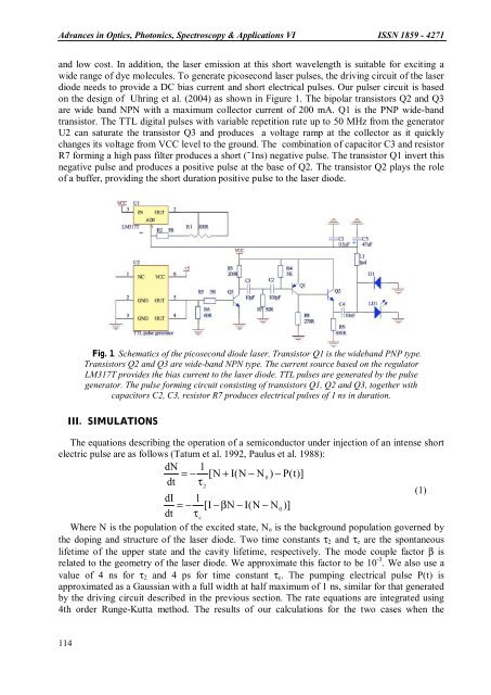
Advances in Optics, Photonics, Spectroscopy & Applications <strong>VI</strong> <strong>ISSN</strong> <strong>1859</strong> - <strong>4271</strong>and low cost. In addition, the laser emission at this short wavele<strong>ng</strong>th is suitable for exci<s<stro<strong>ng</strong>>tro<strong>ng</strong></stro<strong>ng</strong>>>tin</s<stro<strong>ng</strong>>tro<strong>ng</strong></stro<strong>ng</strong>>>g awide ra<strong>ng</strong>e of dye molecules. To generate picosecond laser pulses, the drivi<strong>ng</strong> circuit of the laserdiode needs to provide a DC bias current and short electrical pulses. Our pulser circuit is basedon the design of Uhri<strong>ng</strong> et al. (2004) as shown in Figure 1. The bipolar transistors Q2 and Q3are wide band NPN with a maximum collector current of 200 mA. Q1 is the PNP wide-bandtransistor. The TTL digital pulses with variable repetition rate up to 50 MHz from the generatorU2 can saturate the transistor Q3 and produces a voltage ramp at the collector as it quicklycha<strong>ng</strong>es its voltage from VCC level to the ground. The combination of capacitor C3 and resistorR7 formi<strong>ng</strong> a high pass filter produces a short (˜1ns) negative pulse. The transistor Q1 invert thisnegative pulse and produces a positive pulse at the base of Q2. The transistor Q2 plays the roleof a buffer, providi<strong>ng</strong> the short duration positive pulse to the laser diode.Fig. 1. Schematics of the picosecond diode laser. Transistor Q1 is the wideband PNP type.Transistors Q2 and Q3 are wide-band NPN type. The current source based on the regulatorLM317T provides the bias current to the laser diode. TTL pulses are generated by the pulsegenerator. The pulse formi<strong>ng</strong> circuit consis<s<stro<strong>ng</strong>>tro<strong>ng</strong></stro<strong>ng</strong>>>tin</s<stro<strong>ng</strong>>tro<strong>ng</strong></stro<strong>ng</strong>>>g of transistors Q1, Q2 and Q3, together wit<stro<strong>ng</strong>>hc</stro<strong>ng</strong>>apacitors C2, C3, resistor R7 produces electrical pulses of 1 ns in duration.III. SIMULATIONSThe equations describi<strong>ng</strong> the operation of a semiconductor under injection of an intense shortelectric pulse are as follows (Tatum et al. 1992, Paulus et al. 1988):dN 1= − [N + I(N − N0) − P(t)]dt τ2(1)dI 1= − [I − βN− I(N − N0)]dt τcWhere N is the population of the excited state, N o is the background population governed bythe dopi<strong>ng</strong> and structure of the laser diode. Two time constants τ 2 and τ c are the spontaneouslifetime of the upper state and the cavity lifetime, respectively. The mode couple factor β isrelated to the geometry of the laser diode. We approximate this factor to be 10 -3 . We also use avalue of 4 ns for τ 2 and 4 ps for time constant τ c . The pumpi<strong>ng</strong> electrical pulse P(t) isapproximated as a Gaussian with a full width at half maximum of 1 ns, similar for that generatedby the drivi<strong>ng</strong> circuit described in the previous section. The rate equations are integrated usi<strong>ng</strong>4th order Ru<strong>ng</strong>e-Kutta method. The results of our calculations for the two cases when the114