Nhng tin b trong Quang hc, Quang ph và ng dng VI ISSN 1859 - 4271
Nhng tin b trong Quang hc, Quang ph và ng dng VI ISSN 1859 - 4271
Nhng tin b trong Quang hc, Quang ph và ng dng VI ISSN 1859 - 4271

Create successful ePaper yourself
Turn your PDF publications into a flip-book with our unique Google optimized e-Paper software.
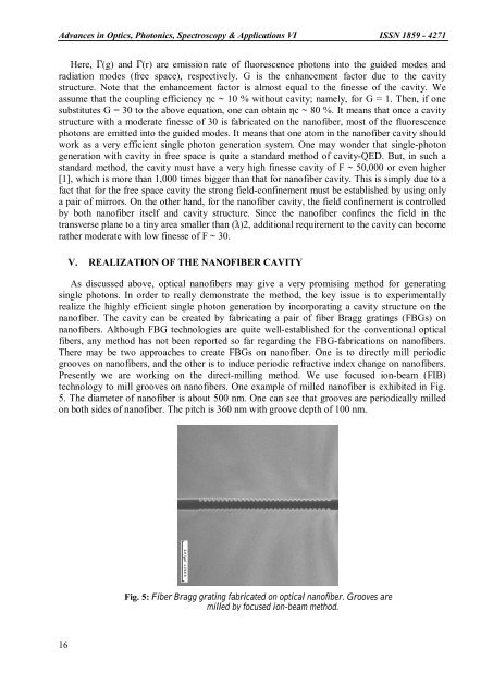
Advances in Optics, Photonics, Spectroscopy & Applications <strong>VI</strong> <strong>ISSN</strong> <strong>1859</strong> - <strong>4271</strong>Here, Γ(g) and Γ(r) are emission rate of fluorescence <stro<strong>ng</strong>>ph</stro<strong>ng</strong>>otons into the guided modes andradiation modes (free space), respectively. G is the enhancement factor due to the cavitystructure. Note that the enhancement factor is almost equal to the finesse of the cavity. Weassume that the coupli<strong>ng</strong> efficiency ηc ~ 10 % without cavity; namely, for G = 1. Then, if onesubstitutes G = 30 to the above equation, one can obtain ηc ~ 80 %. It means that once a cavitystructure with a moderate finesse of 30 is fabricated on the nanofiber, most of the fluorescence<stro<strong>ng</strong>>ph</stro<strong>ng</strong>>otons are emitted into the guided modes. It means that one atom in the nanofiber cavity shouldwork as a very efficient si<strong>ng</strong>le <stro<strong>ng</strong>>ph</stro<strong>ng</strong>>oton generation system. One may wonder that si<strong>ng</strong>le-<stro<strong>ng</strong>>ph</stro<strong>ng</strong>>oto<strong>ng</strong>eneration with cavity in free space is quite a standard method of cavity-QED. But, in such astandard method, the cavity must have a very high finesse cavity of F ~ 50,000 or even higher[1], which is more than 1,000 times bigger than that for nanofiber cavity. This is simply due to afact that for the free space cavity the s<stro<strong>ng</strong>>tro<strong>ng</strong></stro<strong>ng</strong>> field-confinement must be established by usi<strong>ng</strong> onlya pair of mirrors. On the other hand, for the nanofiber cavity, the field confinement is controlledby both nanofiber itself and cavity structure. Since the nanofiber confines the field in thetransverse plane to a <s<stro<strong>ng</strong>>tro<strong>ng</strong></stro<strong>ng</strong>>>tin</s<stro<strong>ng</strong>>tro<strong>ng</strong></stro<strong>ng</strong>>>y area smaller than (λ)2, additional requirement to the cavity can becomerather moderate with low finesse of F ~ 30.V. REALIZATION OF THE NANOFIBER CA<strong>VI</strong>TYAs discussed above, optical nanofibers may give a very promisi<strong>ng</strong> method for genera<s<stro<strong>ng</strong>>tro<strong>ng</strong></stro<strong>ng</strong>>>tin</s<stro<strong>ng</strong>>tro<strong>ng</strong></stro<strong>ng</strong>>>gsi<strong>ng</strong>le <stro<strong>ng</strong>>ph</stro<strong>ng</strong>>otons. In order to really demonstrate the method, the key issue is to experimentallyrealize the highly efficient si<strong>ng</strong>le <stro<strong>ng</strong>>ph</stro<strong>ng</strong>>oton generation by incorpora<s<stro<strong>ng</strong>>tro<strong>ng</strong></stro<strong>ng</strong>>>tin</s<stro<strong>ng</strong>>tro<strong>ng</strong></stro<strong>ng</strong>>>g a cavity structure on thenanofiber. The cavity can be created by fabrica<s<stro<strong>ng</strong>>tro<strong>ng</strong></stro<strong>ng</strong>>>tin</s<stro<strong>ng</strong>>tro<strong>ng</strong></stro<strong>ng</strong>>>g a pair of fiber Bragg gra<s<stro<strong>ng</strong>>tro<strong>ng</strong></stro<strong>ng</strong>>>tin</s<stro<strong>ng</strong>>tro<strong>ng</strong></stro<strong>ng</strong>>>gs (FBGs) onnanofibers. Although FBG technologies are quite well-established for the conventional opticalfibers, any method has not been reported so far regardi<strong>ng</strong> the FBG-fabrications on nanofibers.There may be two approaches to create FBGs on nanofiber. One is to directly mill periodicgrooves on nanofibers, and the other is to induce periodic refractive index cha<strong>ng</strong>e on nanofibers.Presently we are worki<strong>ng</strong> on the direct-milli<strong>ng</strong> method. We use focused ion-beam (FIB)technology to mill grooves on nanofibers. One example of milled nanofiber is exhibited in Fig.5. The diameter of nanofiber is about 500 nm. One can see that grooves are periodically milledon both sides of nanofiber. The pitch is 360 nm with groove depth of 100 nm.Fig. 5: Fiber Bragg gra<s<stro<strong>ng</strong>>tro<strong>ng</strong></stro<strong>ng</strong>>>tin</s<stro<strong>ng</strong>>tro<strong>ng</strong></stro<strong>ng</strong>>>g fabricated on optical nanofiber. Grooves aremilled by focused ion-beam method.16