1. Basic Concepts in Reliability Design - nl3prc
1. Basic Concepts in Reliability Design - nl3prc
1. Basic Concepts in Reliability Design - nl3prc

You also want an ePaper? Increase the reach of your titles
YUMPU automatically turns print PDFs into web optimized ePapers that Google loves.
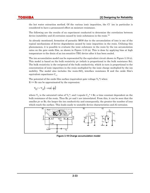
[2] <strong>Design</strong><strong>in</strong>g for <strong>Reliability</strong>the hot water extraction method. Of the various ionic impurities, the Cl − ion <strong>in</strong> particular isconsidered to have a pronounced effect on moisture resistance.The follow<strong>in</strong>g are the results of an experiment conducted to determ<strong>in</strong>e the correlation betweendevice <strong>in</strong>stability and Al corrosion caused by ionic substances <strong>in</strong> the res<strong>in</strong>. 10)As already mentioned, formation of parasitic MOS due to the accumulation of ions is one of thetypical mechanisms of device degradation caused by ionic impurities <strong>in</strong> the res<strong>in</strong>. Utiliz<strong>in</strong>g thisphenomenon, it is possible to evaluate the ionic substance <strong>in</strong> the res<strong>in</strong> by the ion accumulationrates on the gate oxide film, as shown <strong>in</strong> Figure 3.19 (a). This is done by apply<strong>in</strong>g bias at hightemperature to the dra<strong>in</strong> of an ion-sensitive TEG device after it has been sealed.The ion accumulation model can be represented by the equivalent circuit shown <strong>in</strong> Figure 3.19 (c).This model is based on the bulk resistivity ρv (which is proportional to the bulk resistance Rr).The bulk resistivity is the reciprocal of the bulk conductivity, which <strong>in</strong> turn is proportional to theconcentration of ionic impurities <strong>in</strong> the res<strong>in</strong> multiplied by the ionic charge multiplied by the ionmobility. The model also <strong>in</strong>cludes the res<strong>in</strong>-SiO 2 <strong>in</strong>terface resistance R and the oxide film’sequivalent capacitance C ox .The potential of the oxide film surface (equivalent gate voltage V G *) whenR >> Rr can be approximated by the expression:VG∗ ≈ VA{ 1−exp( − )} twhere V A is the saturated value of V G *, and τ equals C ox * Rr, a time constant dependent on thebulk resistance of the res<strong>in</strong>. Thus Rr, ρv and τ are <strong>in</strong>terrelated. From this, it can be seen that thesmaller ρv or Rr, the larger the ion conductivity and consequently, the greater the number of ionswhich reach the surface. This leads easily to unstable device characteristics and Al corrosion.a)b)c)Res<strong>in</strong>R rSourceN + N +I DSP wellDra<strong>in</strong>I DSC OXV GV DR DV G+−+−R rV DI DSV DFigure 3.19 Charge accumulation model2-33