1. Basic Concepts in Reliability Design - nl3prc
1. Basic Concepts in Reliability Design - nl3prc
1. Basic Concepts in Reliability Design - nl3prc

Create successful ePaper yourself
Turn your PDF publications into a flip-book with our unique Google optimized e-Paper software.
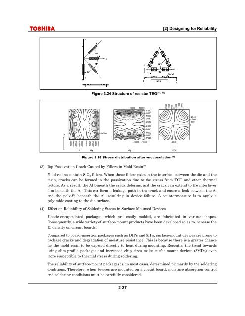
[2] <strong>Design</strong><strong>in</strong>g for <strong>Reliability</strong>28), 29)Figure 3.24 Structure of resistor TEGY−14700−15680−16660−17640−18620−19600−20580−22540−21560−20580−19600−18620−17640294019609800−980−1960−2940−2940−1960−9800−15680−16660−17640−18620−19600−19600−18620−17640−16660−15680−15680−16660−2940XσyσyτxyFigure 3.25 Stress distribution after encapsulation 28)(3) Top Passivation Crack Caused by Fillers <strong>in</strong> Mold Res<strong>in</strong> 30)Mold res<strong>in</strong>s conta<strong>in</strong> SiO 2 fillers. When these fillers exist <strong>in</strong> the <strong>in</strong>terface between the die and theres<strong>in</strong>, cracks can be formed <strong>in</strong> the passivation due to the stress from TCT and other thermalfactors. As a result, the Al beneath the crack deforms, and the crack can extend to the <strong>in</strong>terlayerfilm beneath the Al. This can form a leakage path <strong>in</strong> the crack and cause a leak between the Aland the poly-Si beneath the Al, result<strong>in</strong>g <strong>in</strong> device failure. A countermeasure is to apply apolyimide coat<strong>in</strong>g to the die surface.(4) Effect on <strong>Reliability</strong> of Solder<strong>in</strong>g Stress <strong>in</strong> Surface-Mounted DevicesPlastic-encapsulated packages, which are easily molded, are fabricated <strong>in</strong> various shapes.Consequently, a wide variety of surface-mount products have been developed so as to <strong>in</strong>crease theIC density on circuit boards.Compared to board-<strong>in</strong>sertion packages such as DIPs and SIPs, surface-mount devices are prone topackage cracks and degradation of moisture resistance. This is because there is a greater chancefor the mold res<strong>in</strong> to be exposed directly to heat dur<strong>in</strong>g mount<strong>in</strong>g. Recently, the trend towardsus<strong>in</strong>g slim-profile packages and <strong>in</strong>creased chip sizes make surfac-mount devices (SMDs) evenmore susceptible to thermal stress dur<strong>in</strong>g solder<strong>in</strong>g.The reliability of surface-mount packages is, <strong>in</strong> most cases, determ<strong>in</strong>ed primarily by the solder<strong>in</strong>gconditions. Therefore, when devices are mounted on a circuit board, moisture absorption controland solder<strong>in</strong>g conditions must be carefully considered.2-37