- Page 2 and 3:
TABLE OF CONTENTSPREFACE………
- Page 4 and 5:
7.9 DETAILS OF THE 3GPP CANDIDATE T
- Page 6 and 7:
Rogers expects to cover 80 percent
- Page 8 and 9:
efficiently supported services wher
- Page 10 and 11:
1 INTRODUCTIONWireless data usage i
- Page 12 and 13:
2 PROGRESS OF RELEASE 99, RELEASE 5
- Page 14 and 15:
Mobilkom Austria completed the firs
- Page 16 and 17:
download speed on the downlink and
- Page 18 and 19:
Mbps without deploying MIMO. As pre
- Page 20 and 21:
Figure 3.1. 3GPP UMTS-HSPA Timeline
- Page 22 and 23:
paired and unpaired spectrum. In es
- Page 24 and 25:
complete ecosystem. Some manufactur
- Page 26 and 27:
4 THE GROWING DEMANDS FOR WIRELESS
- Page 28 and 29:
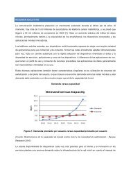
4.1 WIRELESS DATA TRENDS AND FORECA
- Page 30 and 31:
Philippines by Smart Communications
- Page 32 and 33:
IMS Research forecasted complementa
- Page 34 and 35:
The wireless enterprise is becoming
- Page 36 and 37:
spend about the same amount of time
- Page 38 and 39:
to one. The reality is that far mor
- Page 40 and 41:
LBS revenues are expected grow at 1
- Page 42 and 43:
4.6 SUMMARYFor some operators, LTE
- Page 44 and 45:
IPSGiMMES11GWS5S1-MMES1-UeNodeFigur
- Page 46 and 47:
6.1.2 MIMO + DC-HSDPARel-8 introduc
- Page 48 and 49:
4. All UEs are allowed. Along with
- Page 50 and 51:
Alert Service (CMAS) to allow wirel
- Page 52 and 53:
Federal Government entity (i.e. FEM
- Page 54 and 55:
ATIS WTSC G3GSN and TIA TR45.8 Subc
- Page 56 and 57:
ooInteracts with UE to exchange loc
- Page 58 and 59: OTDOA METHODThe OTDOA method is a d
- Page 60 and 61: With CSFB, UE under EPS can enjoy t
- Page 62 and 63: • MSC for GERAN/UTRANooMaintainin
- Page 64 and 65: 6.2.5.3 MBMS SPECIFIC REFERENCE POI
- Page 66 and 67: 6.2.5.5 MBMS SERVICE PROVISIONINGAn
- Page 68 and 69: 6.2.7 ENHANCED DOWNLINK BEAMFORMING
- Page 70 and 71: ate. After an initial measurement p
- Page 72 and 73: Srv) is an optional function allowi
- Page 74 and 75: VPLMNHPLMNCSGList SrvHSSC1 (OMA DM
- Page 76 and 77: 7 STATUS OF IMT-ADVANCED, LTE-ADVAN
- Page 78 and 79: 3GPP plays an important role in IMT
- Page 80 and 81: euse factor, where the effective ba
- Page 82 and 83: Table 7.2. Cell Edge User Spectral
- Page 84 and 85: 7.4.7 HANDOVERThe handover interrup
- Page 86 and 87: • IMT-ADV/8. Acknowledgement of c
- Page 88 and 89: In the WRC-07, the following spectr
- Page 90 and 91: 7.6.2 DEFINING THE LTE-ADVANCED CAP
- Page 92 and 93: ITU-ROutside ITU-RStep 1Circular Le
- Page 94 and 95: It is important to note that the sa
- Page 96 and 97: 7.8 POTENTIAL FEATURES/TECHNOLOGIES
- Page 98 and 99: Component carrierFreq.Modulated dat
- Page 100 and 101: the optimal scheme to reach MU-MIMO
- Page 102 and 103: Intra-site CoMPBS3BS2Inter-site CoM
- Page 104 and 105: freedom at a cell site. The latter
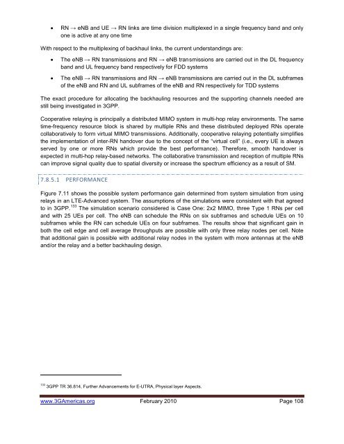
- Page 106 and 107: UnUuUERNeNBFigure 7.10. A Diagramma
- Page 110 and 111: • Mobility Load Balancing. Relate
- Page 112 and 113: has defined a work item on Network
- Page 114 and 115: oFor LTE Rel-10:• The FDD RIT Com
- Page 116 and 117: 8 CONCLUSIONSWireless data usage an
- Page 118 and 119: Alcatel-Lucent has long been active
- Page 120 and 121: Siemens Networks and Sony Ericsson
- Page 122 and 123: Converged Mobility Management (HLR,
- Page 124 and 125: • July 2009: Huawei launched the
- Page 126 and 127: applications for fixed, mobile and
- Page 128 and 129: LTE networks in February 2009. Noki
- Page 130 and 131: 5. Has made massive investments: U.
- Page 132 and 133: Based on its Emerging Ultra-mobile
- Page 134 and 135: 2. Location-Based Services. Locatio
- Page 136 and 137: diversity of app use. In our resear
- Page 138 and 139: • The first NFC devices will be s
- Page 140 and 141: some of these new formats will surp
- Page 142 and 143: the use of MIMO. Furthermore, it do
- Page 144 and 145: UTRANSGSNGERANS3S5S1-MMEMMES11LTE-U
- Page 146 and 147: • Mobility Management Entity (MME
- Page 148 and 149: • Decapsulation/Encapsulation of
- Page 150 and 151: • S2a: The S2a interface provides
- Page 152 and 153: Application / Service LayerUL Servi
- Page 154 and 155: USIM / AuCUE / HSSUE / ASMEKCK, IKK
- Page 156 and 157: C.2.1.6.4ROAMING AND NON-ROAMING SC
- Page 158 and 159:
C.2.2E-UTRAN AIR-INTERFACEThis sect
- Page 160 and 161:
C.2.2.1.2LTE DOWNLINK FRAME STRUCTU
- Page 162 and 163:
One downlink slot TslotNDLsymbOFDM
- Page 164 and 165:
freqtimeControl Region Data RegionO
- Page 166 and 167:
Table C.3. UE Search Space Summary.
- Page 168 and 169:
handover decisions. Two types of sy
- Page 170 and 171:
which the cells should be synchroni
- Page 172 and 173:
of offered bandwidth. UEs were rand
- Page 174 and 175:
far problem is present due to the o
- Page 176 and 177:
parameterization was chosen in such
- Page 178 and 179:
Table C.5. Random Access Burst Para
- Page 180 and 181:
Figure C.29. LTE UL Spectrum Effici
- Page 182 and 183:
eNBInter Cell RRMRB ControlConnecti
- Page 184 and 185:
technology forms dynamic beams that
- Page 186 and 187:
MIMO: SPACE-TIME CODINGSpace-time c
- Page 188 and 189:
sufficient. When several users are
- Page 190 and 191:
0.060Downlink Cell Edge Spectral Ef
- Page 192 and 193:
C.2.2.5INTERFERENCE MITIGATION TECH
- Page 194 and 195:
Node-B755 263 741 526 374 136741 52
- Page 196 and 197:
Table C.6. Features Only Available
- Page 198 and 199:
Table C.8. DwPTS/GP/UpPTS Length (O
- Page 200 and 201:
In 3GPP Rel-8, as a result of the s
- Page 202 and 203:
USIM in LTE networks is not just a
- Page 204 and 205:
APPENDIX D: GLOBAL 3G DEPLOYMENT ST
- Page 206 and 207:
French West Indies Outremer Telecom
- Page 208 and 209:
Philippines Globe Telecom In Servic
- Page 210 and 211:
Ukraine Kyivstar Planned/In Deploym
- Page 212 and 213:
UK O2 (UK) In Service In ServiceUK
- Page 214 and 215:
APPENDIX E: GLOBAL LAUNCHES OF HSPA
- Page 216 and 217:
Colombia Colombia Movil Tigo Colomb
- Page 218 and 219:
USA CenturyTel (700) 2010USA Cox Co
- Page 220 and 221:
Full-buffer spectrum efficiencyEval
- Page 222 and 223:
Detailed Self-Evaluation ResultsDow
- Page 224 and 225:
Cell-average and Cell-edge spectrum
- Page 226 and 227:
Cell-average and Cell-edge spectrum
- Page 228 and 229:
VoIP results (FDD)• LTE Rel. 8 fu
- Page 230 and 231:
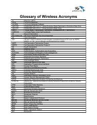
APPENDIX H: ACRONYM LIST1xShort for
- Page 232 and 233:
DIPDominant Interferer ProportionDL
- Page 234 and 235:
IDFTIECIEEEIETF RFCIFFTIFOMI-HSPAIM
- Page 236 and 237:
NI-LRNetwork Induced Location Reque
- Page 238 and 239:
SGSGiSGSNS-GWSICS-ICICSIMSIMOSINRSI
- Page 240:
ACKNOWLEDGMENTSThe mission of 3G Am