UMTS: Alive and Well - 4G Americas
UMTS: Alive and Well - 4G Americas
UMTS: Alive and Well - 4G Americas

You also want an ePaper? Increase the reach of your titles
YUMPU automatically turns print PDFs into web optimized ePapers that Google loves.
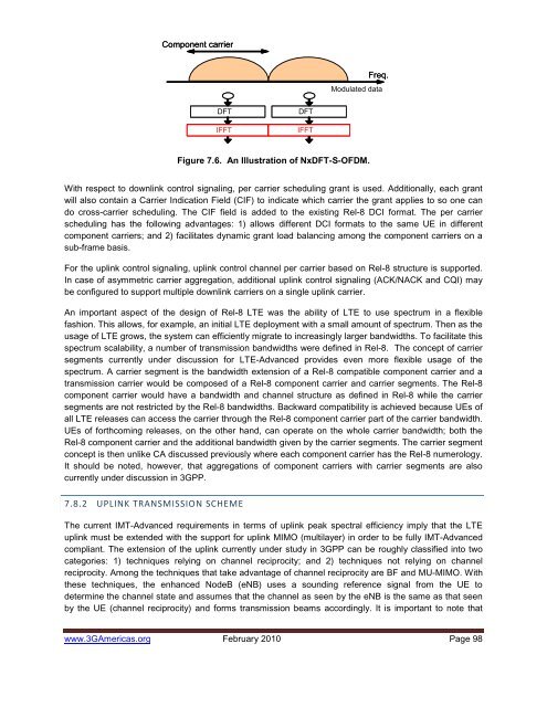
Component carrierFreq.Modulated dataDFTIFFTDFTIFFTFigure 7.6. An Illustration of NxDFT-S-OFDM.With respect to downlink control signaling, per carrier scheduling grant is used. Additionally, each grantwill also contain a Carrier Indication Field (CIF) to indicate which carrier the grant applies to so one c<strong>and</strong>o cross-carrier scheduling. The CIF field is added to the existing Rel-8 DCI format. The per carrierscheduling has the following advantages: 1) allows different DCI formats to the same UE in differentcomponent carriers; <strong>and</strong> 2) facilitates dynamic grant load balancing among the component carriers on asub-frame basis.For the uplink control signaling, uplink control channel per carrier based on Rel-8 structure is supported.In case of asymmetric carrier aggregation, additional uplink control signaling (ACK/NACK <strong>and</strong> CQI) maybe configured to support multiple downlink carriers on a single uplink carrier.An important aspect of the design of Rel-8 LTE was the ability of LTE to use spectrum in a flexiblefashion. This allows, for example, an initial LTE deployment with a small amount of spectrum. Then as theusage of LTE grows, the system can efficiently migrate to increasingly larger b<strong>and</strong>widths. To facilitate thisspectrum scalability, a number of transmission b<strong>and</strong>widths were defined in Rel-8. The concept of carriersegments currently under discussion for LTE-Advanced provides even more flexible usage of thespectrum. A carrier segment is the b<strong>and</strong>width extension of a Rel-8 compatible component carrier <strong>and</strong> atransmission carrier would be composed of a Rel-8 component carrier <strong>and</strong> carrier segments. The Rel-8component carrier would have a b<strong>and</strong>width <strong>and</strong> channel structure as defined in Rel-8 while the carriersegments are not restricted by the Rel-8 b<strong>and</strong>widths. Backward compatibility is achieved because UEs ofall LTE releases can access the carrier through the Rel-8 component carrier part of the carrier b<strong>and</strong>width.UEs of forthcoming releases, on the other h<strong>and</strong>, can operate on the whole carrier b<strong>and</strong>width; both theRel-8 component carrier <strong>and</strong> the additional b<strong>and</strong>width given by the carrier segments. The carrier segmentconcept is then unlike CA discussed previously where each component carrier has the Rel-8 numerology.It should be noted, however, that aggregations of component carriers with carrier segments are alsocurrently under discussion in 3GPP.7.8.2 UPLINK TRANSMISSION SCHEMEThe current IMT-Advanced requirements in terms of uplink peak spectral efficiency imply that the LTEuplink must be extended with the support for uplink MIMO (multilayer) in order to be fully IMT-Advancedcompliant. The extension of the uplink currently under study in 3GPP can be roughly classified into twocategories: 1) techniques relying on channel reciprocity; <strong>and</strong> 2) techniques not relying on channelreciprocity. Among the techniques that take advantage of channel reciprocity are BF <strong>and</strong> MU-MIMO. Withthese techniques, the enhanced NodeB (eNB) uses a sounding reference signal from the UE todetermine the channel state <strong>and</strong> assumes that the channel as seen by the eNB is the same as that seenby the UE (channel reciprocity) <strong>and</strong> forms transmission beams accordingly. It is important to note thatwww.3G<strong>Americas</strong>.org February 2010 Page 98