Clike here to get datasheet of CC1101 - Elechouse
Clike here to get datasheet of CC1101 - Elechouse
Clike here to get datasheet of CC1101 - Elechouse

You also want an ePaper? Increase the reach of your titles
YUMPU automatically turns print PDFs into web optimized ePapers that Google loves.
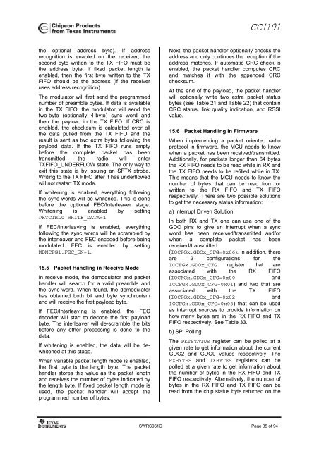
<strong>CC1101</strong>the optional address byte). If addressrecognition is enabled on the receiver, thesecond byte written <strong>to</strong> the TX FIFO must bethe address byte. If fixed packet length isenabled, then the first byte written <strong>to</strong> the TXFIFO should be the address (if the receiveruses address recognition).The modula<strong>to</strong>r will first send the programmednumber <strong>of</strong> preamble bytes. If data is availablein the TX FIFO, the modula<strong>to</strong>r will send thetwo-byte (optionally 4-byte) sync word andthen the payload in the TX FIFO. If CRC isenabled, the checksum is calculated over allthe data pulled from the TX FIFO and t<strong>here</strong>sult is sent as two extra bytes following thepayload data. If the TX FIFO runs emptybefore the complete packet has beentransmitted, the radio will enterTXFIFO_UNDERFLOW state. The only way <strong>to</strong>exit this state is by issuing an SFTX strobe.Writing <strong>to</strong> the TX FIFO after it has underflowedwill not restart TX mode.If whitening is enabled, everything followingthe sync words will be whitened. This is donebefore the optional FEC/Interleaver stage.Whitening is enabled by settingPKTCTRL0.WHITE_DATA=1.If FEC/Interleaving is enabled, everythingfollowing the sync words will be scrambled bythe interleaver and FEC encoded before beingmodulated. FEC is enabled by settingMDMCFG1.FEC_EN=1.15.5 Packet Handling in Receive ModeIn receive mode, the demodula<strong>to</strong>r and packethandler will search for a valid preamble andthe sync word. When found, the demodula<strong>to</strong>rhas obtained both bit and byte synchronismand will receive the first payload byte.If FEC/Interleaving is enabled, the FECdecoder will start <strong>to</strong> decode the first payloadbyte. The interleaver will de-scramble the bitsbefore any other processing is done <strong>to</strong> thedata.If whitening is enabled, the data will be dewhitenedat this stage.When variable packet length mode is enabled,the first byte is the length byte. The packethandler s<strong>to</strong>res this value as the packet lengthand receives the number <strong>of</strong> bytes indicated bythe length byte. If fixed packet length mode isused, the packet handler will accept theprogrammed number <strong>of</strong> bytes.Next, the packet handler optionally checks theaddress and only continues the reception if theaddress matches. If au<strong>to</strong>matic CRC check isenabled, the packet handler computes CRCand matches it with the appended CRCchecksum.At the end <strong>of</strong> the payload, the packet handlerwill optionally write two extra packet statusbytes (see Table 21 and Table 22) that containCRC status, link quality indication, and RSSIvalue.15.6 Packet Handling in FirmwareWhen implementing a packet oriented radiopro<strong>to</strong>col in firmware, the MCU needs <strong>to</strong> knowwhen a packet has been received/transmitted.Additionally, for packets longer than 64 bytesthe RX FIFO needs <strong>to</strong> be read while in RX andthe TX FIFO needs <strong>to</strong> be refilled while in TX.This means that the MCU needs <strong>to</strong> know thenumber <strong>of</strong> bytes that can be read from orwritten <strong>to</strong> the RX FIFO and TX FIFOrespectively. T<strong>here</strong> are two possible solutions<strong>to</strong> <strong>get</strong> the necessary status information:a) Interrupt Driven SolutionIn both RX and TX one can use one <strong>of</strong> theGDO pins <strong>to</strong> give an interrupt when a syncword has been received/transmitted and/orwhen a complete packet has beenreceived/transmitted(IOCFGx.GDOx_CFG=0x06). In addition, t<strong>here</strong>are 2 configurations for theIOCFGx.GDOx_CFG register that areassociated with the RX FIFO(IOCFGx.GDOx_CFG=0x00andIOCFGx.GDOx_CFG=0x01) and two that areassociated with the TX FIFO(IOCFGx.GDOx_CFG=0x02andIOCFGx.GDOx_CFG=0x03) that can be usedas interrupt sources <strong>to</strong> provide information onhow many bytes are in the RX FIFO and TXFIFO respectively. See Table 33.b) SPI PollingThe PKTSTATUS register can be polled at agiven rate <strong>to</strong> <strong>get</strong> information about the currentGDO2 and GDO0 values respectively. TheRXBYTES and TXBYTES registers can bepolled at a given rate <strong>to</strong> <strong>get</strong> information aboutthe number <strong>of</strong> bytes in the RX FIFO and TXFIFO respectively. Alternatively, the number <strong>of</strong>bytes in the RX FIFO and TX FIFO can beread from the chip status byte returned on theSWRS061C Page 35 <strong>of</strong> 94