Clike here to get datasheet of CC1101 - Elechouse
Clike here to get datasheet of CC1101 - Elechouse
Clike here to get datasheet of CC1101 - Elechouse

You also want an ePaper? Increase the reach of your titles
YUMPU automatically turns print PDFs into web optimized ePapers that Google loves.
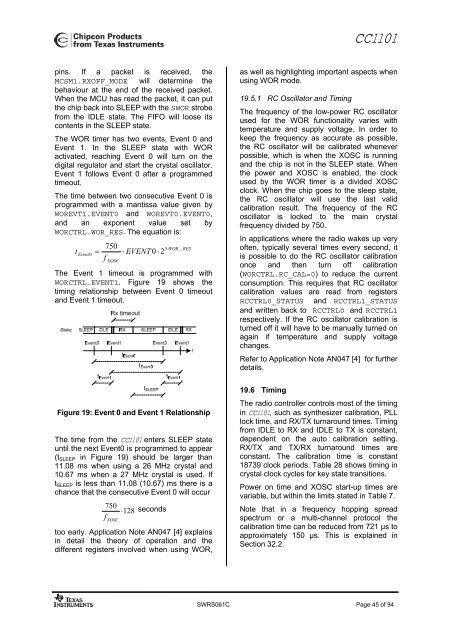
<strong>CC1101</strong>pins. If a packet is received, theMCSM1.RXOFF_MODE will determine thebehaviour at the end <strong>of</strong> the received packet.When the MCU has read the packet, it can putthe chip back in<strong>to</strong> SLEEP with the SWOR strobefrom the IDLE state. The FIFO will loose itscontents in the SLEEP state.The WOR timer has two events, Event 0 andEvent 1. In the SLEEP state with WORactivated, reaching Event 0 will turn on thedigital regula<strong>to</strong>r and start the crystal oscilla<strong>to</strong>r.Event 1 follows Event 0 after a programmedtimeout.The time between two consecutive Event 0 isprogrammed with a mantissa value given byWOREVT1.EVENT0 and WOREVT0.EVENT0,and an exponent value set byWORCTRL.WOR_RES. The equation is:t750 ⋅5 WOR _ RESEvent0 = ⋅ EVENT 0 ⋅ 2fXOSCThe Event 1 timeout is programmed withWORCTRL.EVENT1. Figure 19 shows thetiming relationship between Event 0 timeoutand Event 1 timeout.as well as highlighting important aspects whenusing WOR mode.19.5.1 RC Oscilla<strong>to</strong>r and TimingThe frequency <strong>of</strong> the low-power RC oscilla<strong>to</strong>rused for the WOR functionality varies withtemperature and supply voltage. In order <strong>to</strong>keep the frequency as accurate as possible,the RC oscilla<strong>to</strong>r will be calibrated wheneverpossible, which is when the XOSC is runningand the chip is not in the SLEEP state. Whenthe power and XOSC is enabled, the clockused by the WOR timer is a divided XOSCclock. When the chip goes <strong>to</strong> the sleep state,the RC oscilla<strong>to</strong>r will use the last validcalibration result. The frequency <strong>of</strong> the RCoscilla<strong>to</strong>r is locked <strong>to</strong> the main crystalfrequency divided by 750.In applications w<strong>here</strong> the radio wakes up very<strong>of</strong>ten, typically several times every second, itis possible <strong>to</strong> do the RC oscilla<strong>to</strong>r calibrationonce and then turn <strong>of</strong>f calibration(WORCTRL.RC_CAL=0) <strong>to</strong> reduce the currentconsumption. This requires that RC oscilla<strong>to</strong>rcalibration values are read from registersRCCTRL0_STATUS and RCCTRL1_STATUSand written back <strong>to</strong> RCCTRL0 and RCCTRL1respectively. If the RC oscilla<strong>to</strong>r calibration isturned <strong>of</strong>f it will have <strong>to</strong> be manually turned onagain if temperature and supply voltagechanges.Refer <strong>to</strong> Application Note AN047 [4] for furtherdetails.Figure 19: Event 0 and Event 1 RelationshipThe time from the <strong>CC1101</strong> enters SLEEP stateuntil the next Event0 is programmed <strong>to</strong> appear(t SLEEP in Figure 19) should be larger than11.08 ms when using a 26 MHz crystal and10.67 ms when a 27 MHz crystal is used. Ift SLEEP is less than 11.08 (10.67) ms t<strong>here</strong> is achance that the consecutive Event 0 will occur750 ⋅128 secondsf XOSC<strong>to</strong>o early. Application Note AN047 [4] explainsin detail the theory <strong>of</strong> operation and thedifferent registers involved when using WOR,19.6 TimingThe radio controller controls most <strong>of</strong> the timingin <strong>CC1101</strong>, such as synthesizer calibration, PLLlock time, and RX/TX turnaround times. Timingfrom IDLE <strong>to</strong> RX and IDLE <strong>to</strong> TX is constant,dependent on the au<strong>to</strong> calibration setting.RX/TX and TX/RX turnaround times areconstant. The calibration time is constant18739 clock periods. Table 28 shows timing incrystal clock cycles for key state transitions.Power on time and XOSC start-up times arevariable, but within the limits stated in Table 7.Note that in a frequency hopping spreadspectrum or a multi-channel pro<strong>to</strong>col thecalibration time can be reduced from 721 µs <strong>to</strong>approximately 150 µs. This is explained inSection 32.2.SWRS061C Page 45 <strong>of</strong> 94