PAXI PAXC PAXR Data Sheet/Manual PDF - Red Lion Controls
PAXI PAXC PAXR Data Sheet/Manual PDF - Red Lion Controls
PAXI PAXC PAXR Data Sheet/Manual PDF - Red Lion Controls

You also want an ePaper? Increase the reach of your titles
YUMPU automatically turns print PDFs into web optimized ePapers that Google loves.
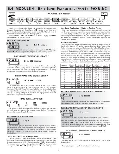
6.4 MODULE 4 - RATE INPUT PARAMETERS (�����) - <strong>PAXR</strong> & I<br />
Module 4 is the programming for the Rate parameters. For maximum input<br />
frequency, Rate assignment should be set to �� when not in use. When set to<br />
��, the remaining related parameters are not accessible. The Rate value is<br />
shown with an annunciator of ‘�’ in the Display Mode.<br />
Note: For <strong>PAXR</strong>, ���� is actually ������ on the unit’s display and ���� is<br />
actually ������ on the unit’s display.<br />
<strong>PAXI</strong>: RATE ASSIGNMENT<br />
������ �<br />
� ������<br />
For measuring the rate (speed) of pulses on Input A, select ������. For Input<br />
B select ������. This assignment is independent of the counting modes.<br />
������ �<br />
� ���<br />
LOW UPDATE TIME (DISPLAY UPDATE) *<br />
����to������seconds<br />
The Low Update Time is the minimum amount of time between display<br />
updates for the Rate display. Values of 0.1 and 0.2 seconds will update the<br />
display correctly but may cause the display to appear unsteady. The factory<br />
setting of 1.0 will update the display every second minimum.<br />
HIGH UPDATE TIME (DISPLAY ZERO) *<br />
������ � ����to������seconds<br />
�<br />
���<br />
The High Update Time is the maximum amount of time before the Rate<br />
display is forced to zero. (For more explanation, refer to Input Frequency<br />
Calculation.) The High Update Time must be higher than the Low Update Time<br />
and higher than the desired slowest readable speed (one divided by pulses per<br />
second). The factory setting of 2.0, will force the display to zero for speeds<br />
below 0.5 Hz or a pulse every 2 seconds.<br />
������<br />
�<br />
�<br />
�<br />
RATE DECIMAL POSITION<br />
This selects the decimal point position for Rate, Minimum and Maximum<br />
rate displays and any setpoint value assigned to these displays. This parameter<br />
does not affect rate scaling calculations.<br />
<strong>PAXI</strong>: LINEARIZER SEGMENTS<br />
�<br />
����<br />
�<br />
�<br />
�� ������ ������<br />
� ���� ������<br />
��� �����<br />
��to��<br />
This parameter specifies the number of linear segments used for the Rate<br />
Scaling function. Each linear segment has two scaling points which define the<br />
upper and lower endpoints of the segment. The number of segments used<br />
depends on the linearity of the process and the display accuracy required as<br />
described below.<br />
Linear Application – 2 Scaling Points<br />
Linear processes use a single segment (two scaling points) to provide a linear<br />
Rate display from 0 up to the maximum input frequency. For typical zero based<br />
frequency measurements (0 Hz = 0 on display), leave ������ (factory setting).<br />
For non-zero based 2 scaling point applications, set ������, to enter both the<br />
zero segment (������ & ������) and segment 1 (�������& ������).<br />
PARAMETER MENU<br />
18<br />
Non-linear Application – Up to 10 Scaling Points<br />
Non-linear processes may utilize up to nine segments (ten scaling points) to<br />
provide a piece-wise linear approximation representing the non-linear function.<br />
The Rate display will be linear throughout each individual segment (i.e.<br />
between sequential scaling points). Thus, the greater the number of segments,<br />
the greater the conformity accuracy. Several linearization equations are<br />
available in the software.<br />
About Scaling Points<br />
Each Scaling Point is specified by two programmable parameters: A desired<br />
Rate Display Value (����) and a corresponding Rate Input Value (����).<br />
Scaling points are entered sequentially in ascending order of Rate Input Value.<br />
Two scaling points must be programmed to define the upper and lower<br />
endpoints of the first linear segment. Setting ������, automatically factory sets<br />
the first scaling point to 0.0 for typical single segment, zero based applications.<br />
When multiple segments are used, the upper scaling point for a given segment<br />
becomes the lower scaling point for the next sequential segment. Thus, for each<br />
additional segment used, only one additional scaling point must be programmed.<br />
The following chart shows the Scaling Points, the corresponding Parameter<br />
mnemonics, and the Factory Default Settings for each point.<br />
SEGMENT<br />
<strong>PAXI</strong>: RATE DISPLAY VALUE FOR SCALING POINT 1<br />
������<br />
�<br />
�<br />
�<br />
Confirm the Rate Display Value for the first Scaling Point is 0. This parameter<br />
is automatically set to 0 and does not appear when ������. (See Note)<br />
<strong>PAXI</strong>: RATE INPUT VALUE FOR SCALING POINT 1<br />
������ �<br />
� ���<br />
Confirm the Rate Input Value for the first Scaling Point is 0.0. (See Note)<br />
Note: For all linear and most non-linear applications, the Scaling Point 1<br />
parameters (����� � and ����� �) should be set to 0 and 0.0 respectively.<br />
Consult the factory before using any non-zero values for Scaling Point 1. These<br />
parameters are automatically set to 0 and do not appear when ������.<br />
������<br />
�<br />
1<br />
2<br />
3<br />
4<br />
5<br />
6<br />
7<br />
8<br />
9<br />
SCALING<br />
POINT<br />
1<br />
2<br />
3<br />
4<br />
5<br />
6<br />
7<br />
8<br />
9<br />
10<br />
RATE DISPLAY VALUE FOR SCALING POINT 2<br />
�<br />
����<br />
DISPLAY<br />
PARAMETER<br />
������<br />
������<br />
������<br />
������<br />
������<br />
������<br />
������<br />
������<br />
������<br />
������<br />
DISPLAY<br />
DEFAULT<br />
000000<br />
001000<br />
002000<br />
003000<br />
004000<br />
005000<br />
006000<br />
007000<br />
008000<br />
009000<br />
��to�������<br />
��to��������<br />
��to�������<br />
INPUT<br />
PARAMETER<br />
������<br />
������<br />
������<br />
������<br />
������<br />
������<br />
������<br />
������<br />
������<br />
������<br />
Enter the desired Rate Display Value for the second Scaling Point by using<br />
the arrow keys.<br />
* Factory Setting can be used without affecting basic start-up.<br />
INPUT<br />
DEFAULT<br />
00000.0<br />
01000.0<br />
02000.0<br />
03000.0<br />
04000.0<br />
05000.0<br />
06000.0<br />
07000.0<br />
08000.0<br />
09000.0