PAXI PAXC PAXR Data Sheet/Manual PDF - Red Lion Controls
PAXI PAXC PAXR Data Sheet/Manual PDF - Red Lion Controls
PAXI PAXC PAXR Data Sheet/Manual PDF - Red Lion Controls

You also want an ePaper? Increase the reach of your titles
YUMPU automatically turns print PDFs into web optimized ePapers that Google loves.
Tel +1 (717) 767-6511<br />
Fax +1 (717) 764-0839<br />
www.redlion.net<br />
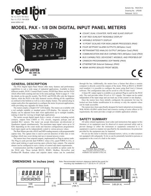
MODEL PAX - 1/8 DIN DIGITAL INPUT PANEL METERS<br />
U L<br />
C R US LISTED<br />
IND. CONT. EQ.<br />
51EB<br />
GENERAL DESCRIPTION<br />
The PAX Digital Input Panel Meters offer many features and performance<br />
capabilities to suit a wide range of industrial applications. Available in three<br />
different models, <strong>PAXC</strong> Counter/Dual Counter, <strong>PAXR</strong> Rate Meter and the <strong>PAXI</strong><br />
which offers both counting and rate in the same package. Refer to pages 4 - 5 for<br />
the details on the specific models. The <strong>PAXC</strong> and <strong>PAXR</strong> offer only the Setpoint<br />
Option, while the <strong>PAXI</strong> is the fully featured version offering all the capabilities<br />
as outlined in this bulletin as well as a slave display feature. The optional plug-in<br />
output cards allow the opportunity to configure the meter for present applications,<br />
while providing easy upgrades for future needs.<br />
The meters employ a bright 0.56" LED display. The meters are available with<br />
a red sunlight readable or standard green LED display. The intensity of the<br />
display can be adjusted from dark room applications up to sunlight readable,<br />
making it ideal for viewing in bright light applications.<br />
The meters accept digital inputs from a variety of sources including switch<br />
contacts, outputs from CMOS or TTL circuits, magnetic pickups and all<br />
standard RLC sensors. The meter can accept directional, uni-directional or<br />
Quadrature signals simultaneously. The maximum input signal varies up to 34<br />
KHz depending on the count mode and function configurations programmed.<br />
Each input signal can be independently scaled to various process values.<br />
The Rate Meters provide a MAX and MIN reading memory with programmable<br />
capture time. The capture time is used to prevent detection of false max or min<br />
readings which may occur during start-up or unusual process events.<br />
The meters have four setpoint outputs, implemented on Plug-in option cards.<br />
The Plug-in cards provide dual FORM-C relays (5A), quad FORM-A (3A), or<br />
either quad sinking or quad sourcing open collector logic outputs. The setpoint<br />
alarms can be configured to suit a variety of control and alarm requirements.<br />
Communication and Bus Capabilities are also available as option cards for<br />
the <strong>PAXI</strong> only. These include RS232, RS485, Modbus, DeviceNet, and<br />
Profibus-DP. Readout values and setpoint alarm values can be controlled<br />
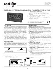
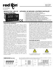
DIMENSIONS In inches (mm)<br />
A<br />
B<br />
C �����������<br />
SP1 SP2 SP3 SP4<br />
DSP PAR F1 F2 RST<br />
3.80<br />
(96.5)<br />
1.95<br />
(49.5)<br />
.10 4.10<br />
(2.5)<br />
(104.1)<br />
1<br />
Bulletin No. <strong>PAXI</strong>CR-H<br />
Drawing No. LP0548<br />
Released 01/11<br />
� COUNT, DUAL COUNTER, RATE AND SLAVE DISPLAY<br />
� 0.56" RED SUNLIGHT READABLE DISPLAY<br />
� VARIABLE INTENSITY DISPLAY<br />
� 10 POINT SCALING FOR NON-LINEAR PROCESSES (<strong>PAXI</strong>)<br />
� FOUR SETPOINT ALARM OUTPUTS (W/Option Card)<br />
� RETRANSMITTED ANALOG OUTPUT (W/Option Card) (<strong>PAXI</strong>)<br />
� COMMUNICATION AND BUS CAPABILITIES (W/Option Card) (<strong>PAXI</strong>)<br />
� BUS CAPABILITIES; DEVICENET, MODBUS, AND PROFIBUS-DP<br />
� CRIMSON PROGRAMMING SOFTWARE (<strong>PAXI</strong>)<br />
� ETHERNET(W/ External Gateway) (<strong>PAXI</strong>)<br />
� NEMA 4X/IP65 SEALED FRONT BEZEL<br />
through the bus. Additionally, the meters have a feature that allows a remote<br />
computer to directly control the outputs of the meter. With an RS232 or RS485<br />
card installed, it is possible to configure the meter using <strong>Red</strong> <strong>Lion</strong>’s Crimson<br />
software. The configuration data can be saved to a file for later recall.<br />
A linear DC output signal is available as an optional Plug-in card for the <strong>PAXI</strong><br />
only. The card provides either 20 mA or 10 V signals. The output can be scaled<br />
independent of the input range and can track any of the counter or rate displays.<br />
Once the meters have been initially configured, the parameter list may be<br />
locked out from further modification in its entirety or only the setpoint values<br />
can be made accessible.<br />
The meters have been specifically designed for harsh industrial environments.<br />
With NEMA 4X/IP65 sealed bezel and extensive testing of noise effects to CE<br />
requirements, the meter provides a tough yet reliable application solution.<br />
SAFETY SUMMARY<br />
All safety related regulations, local codes and instructions that appear in this<br />
literature or on equipment must be observed to ensure personal safety and to<br />
prevent damage to either the instrument or equipment connected to it. If<br />
equipment is used in a manner not specified by the manufacturer, the protection<br />
provided by the equipment may be impaired.<br />
Do not use this meter to directly command motors, valves, or other actuators<br />
not equipped with safeguards. To do so can be potentially harmful to persons or<br />
equipment in the event of a fault to the meter.<br />
CAUTION: Risk of Danger.<br />
Read complete instructions prior to<br />
installation and operation of the unit.<br />
Note: Recommended minimum clearance (behind the panel) for<br />
mounting clip installation is 2.1" (53.4) H x 5" (127) W.<br />
1.75<br />
(44.5)<br />
12 16<br />
13<br />
14<br />
15<br />
1 2 3 4 5 6 7 8 9 10 11<br />
3.60 (91.4)<br />
CAUTION: Risk of electric shock.<br />
17<br />
18<br />
19<br />
20<br />
21<br />
22<br />
23<br />
24<br />
25<br />
1.75<br />
(44.5)
TABLE OF CONTENTS<br />
Ordering Information . . . . . . . . . . . . . . . . . . . . 2<br />
General Meter Specifications . . . . . . . . . . . . . 3<br />
<strong>PAXC</strong> Counter . . . . . . . . . . . . . . . . . . . . . . . . . 4<br />
<strong>PAXR</strong> Rate Meter . . . . . . . . . . . . . . . . . . . . . . 4<br />
<strong>PAXI</strong> Counter/Rate Meter . . . . . . . . . . . . . . . . 5<br />
Optional Plug-In Output Cards . . . . . . . . . . . . 6<br />
Installing the Meter . . . . . . . . . . . . . . . . . . . . . 7<br />
Setting the Jumper and DIP Switches . . . . . . 7<br />
ORDERING INFORMATION<br />
Meter Part Numbers<br />
Option Card and Accessories Part Numbers<br />
2<br />
Installing Plug-In Cards . . . . . . . . . . . . . . . . . . 8<br />
Wiring the Meter . . . . . . . . . . . . . . . . . . . . . . . 9<br />
Reviewing the Front Buttons and Display . . . 11<br />
Programming the Meter. . . . . . . . . . . . . . . . . 12<br />
Factory Service Operations . . . . . . . . . . . . . . 28<br />
Troubleshooting . . . . . . . . . . . . . . . . . . . . . . . 29<br />
Parameter Value Chart . . . . . . . . . . . . . . . . . 30<br />
Programming Overview . . . . . . . . . . . . . . . . . 32<br />
TYPE MODEL NO. DESCRIPTION PART NUMBER<br />
Optional<br />
Plug-In<br />
Cards<br />
PAX 0 0<br />
C - Counter/Dual Counter<br />
R - Rate Meter<br />
I - Counter/Dual Counter/<br />
Rate Meter/Slave Display<br />
0 - <strong>Red</strong>, Sunlight Readable Display<br />
1 - Green Display<br />
0 - 85 to 250 VAC<br />
1 - 11 to 36 VDC, 24 VAC<br />
<strong>PAXC</strong>DS<br />
Dual Setpoint Relay Output Card <strong>PAXC</strong>DS10<br />
Quad Setpoint Relay Output Card <strong>PAXC</strong>DS20<br />
Quad Setpoint Sinking Open Collector Output Card <strong>PAXC</strong>DS30<br />
Quad Setpoint Sourcing Open Collector Output Card <strong>PAXC</strong>DS40<br />
RS485 Serial Communications Card with Terminal Block <strong>PAXC</strong>DC10<br />
Extended RS485 Serial Communications Card with Dual RJ11 Connector <strong>PAXC</strong>DC1C<br />
RS232 Serial Communications Card with Terminal Block <strong>PAXC</strong>DC20<br />
<strong>PAXC</strong>DC<br />
Extended RS232 Serial Communications Card with 9 Pin D Connector<br />
DeviceNet Communications Card<br />
<strong>PAXC</strong>DC2C<br />
<strong>PAXC</strong>DC30<br />
Modbus Communications Card <strong>PAXC</strong>DC40<br />
Extended Modbus Communications Card with Dual RJ11 Connector <strong>PAXC</strong>DC4C<br />
Profibus-DP Communications Card <strong>PAXC</strong>DC50<br />
PAXUSB PAX USB Programming Card (Not included in PAX product UL E179259 file). PAXUSB00<br />
<strong>PAXC</strong>DL Analog Output Card <strong>PAXC</strong>DL10<br />
SFCRD* Crimson PC Configuration Software for Windows 98, ME, 2000 and XP SFCRD200<br />
Accessories<br />
ICM8 Communication Gateway ICM80000<br />
*Crimson software is available for free download from http://www.redlion.net/<br />
Shaded areas are only available for the <strong>PAXI</strong>
GENERAL METER SPECIFICATIONS<br />
1. DISPLAY: 6 digit, 0.56" (14.2 mm) red sunlight readable or standard green<br />
LED<br />
2. POWER:<br />
AC Versions:<br />
AC Power: 85 to 250 VAC, 50/60 Hz, 18 VA<br />
Isolation: 2300 Vrms for 1 min. to all inputs and outputs. (300 V working)<br />
DC Versions:<br />
DC Power: 11 to 36 VDC, 14 W<br />
(derate operating temperature to 40° C if operating 3.6 VDC<br />
V IN > 3.6 VDC V IN < 0.9 VDC<br />
Response Time: 6 msec. typical; function dependent. Certain resets, stores<br />
and inhibits respond within 25 μsec if an edge occurs with the associated<br />
counter or within 6 msec if no count edge occurs with the associated<br />
counter. These functions include ������, ������, ������, ������,<br />
������, �����, and ������. Once activated, all functions are latched for<br />
50 msec min. to 100 msec max. After that period, another edge/level may<br />
be recognized.<br />
6. MEMORY: Nonvolatile E 2PROM retains all programmable parameters and<br />
display values.<br />
7. CERTIFICATIONS AND COMPLIANCES:<br />
SAFETY<br />
UL Recognized Component, File #E179259, UL61010A-1, CSA C22.2<br />
No. 61010-1<br />
Recognized to U.S. and Canadian requirements under the Component<br />
Recognition Program of Underwriters Laboratories, Inc.<br />
UL Listed, File #E137808, UL508, CSA C22.2 No. 14-M95<br />
LISTED by Und. Lab. Inc. to U.S. and Canadian safety standards<br />
Type 4X Enclosure rating (Face only), UL50<br />
IECEE CB Scheme Test Report #04ME11209-20041018<br />
Issued by Underwriters Laboratories, Inc.<br />
IEC 61010-1, EN 61010-1: Safety requirements for electrical equipment<br />
for measurement, control, and laboratory use, Part 1.<br />
IP65 Enclosure rating (Face only), IEC 529<br />
IP20 Enclosure rating (Rear of unit), IEC 529<br />
3<br />
ELECTROMAGNETIC COMPATIBILITY<br />
Emissions and Immunity to EN 61326:2006: Electrical Equipment for<br />
Measurement, Control and Laboratory use.<br />
Immunity to Industrial Locations:<br />
Electrostatic discharge EN 61000-4-2 Criterion A<br />
4 kV contact discharge<br />
8 kV air discharge<br />
Electromagnetic RF fields EN 61000-4-3 Criterion A<br />
10 V/m (80 MHz to 1 GHz)<br />
3 V/m (1.4 GHz to 2 GHz)<br />
1 V/m (2 GHz to 2.7 GHz)<br />
Fast transients (burst) EN 61000-4-4 Criterion A<br />
2 kV power<br />
1 kV I/O signal<br />
2 kV I/O signal connected<br />
to power<br />
Surge EN 61000-4-5 Criterion A<br />
power 1 kV L to L, 2 kV L to G<br />
signal 1 kV<br />
RF conducted interference EN 61000-4-6 Criterion A<br />
3 Vrms<br />
AC power EN 61000-4-11<br />
Voltage dip Criterion A<br />
0% during 1 cycle<br />
40% during 10/12 cycle<br />
70% during 25/30 cycle<br />
Short interruptions<br />
Emissions:<br />
Criterion C<br />
0% during 250/300 cycles<br />
Emissions<br />
Notes:<br />
EN 55011 Class A<br />
1. Criterion A: Normal operation within specified limits.<br />
2. Criterion C: Temporary loss of function where system reset occurs.<br />
Refer to EMC Installation Guidelines section of the bulletin for additional<br />
information.<br />
8. ENVIRONMENTAL CONDITIONS:<br />
Operating Temperature Range: 0 to 50°C (0 to 45°C with all three plug-in<br />
cards installed)<br />
Storage Temperature Range: -40 to 60°C<br />
Operating and Storage Humidity: 0 to 85% max. relative humidity noncondensing<br />
Vibration According to IEC 68-2-6: Operational 5 to 150 Hz, in X, Y, Z<br />
direction for 1.5 hours, 2 g.<br />
Shock According to IEC 68-2-27: Operational 25 g (10 g relay), 11 msec in 3<br />
directions.<br />
Altitude: Up to 2000 meters<br />
9. CONNECTIONS: High compression cage-clamp terminal block<br />
Wire Strip Length: 0.3" (7.5 mm)<br />
Wire Gage: 30-14 AWG copper wire<br />
Torque: 4.5 inch-lbs (0.51 N-m) max.<br />
10. CONSTRUCTION: This unit is rated for NEMA 4X/IP65 outdoor use.<br />
IP20 Touch safe. Installation Category II, Pollution Degree 2. One piece<br />
bezel/case. Flame resistant. Synthetic rubber keypad. Panel gasket and<br />
mounting clip included.<br />
11. WEIGHT: 10.1 oz. (286 g)
MODEL <strong>PAXC</strong> - 1/8 DIN COUNTER<br />
<strong>PAXC</strong> SPECIFICATIONS<br />
MAXIMUM SIGNAL FREQUENCIES:<br />
To determine the maximum frequency for the input(s), first answer the<br />
questions with a yes (Y) or no (N). Next determine the Count Mode to be<br />
used for the counter(s). If dual counters are used with different Count Modes,<br />
then the lowest frequency applies to both counters.<br />
FUNCTION QUESTIONS Single: Counter A or B Dual: Counter A & B<br />
Are any setpoints used? N N Y Y N N Y Y<br />
Is Counter C used? N Y N Y N Y N Y<br />
COUNT MODE (Values are in KHz) (Values are in KHz)<br />
Count x1 34 25 18 15 13 12 9 7.5<br />
Count x2 17 13 9 7 9 7 5 4<br />
Quadrature x1 22 19 12 10 7 6 4 3.5<br />
Quadrature x2 17 13 9 7 7 6 4 3.5<br />
Quadrature x4<br />
Notes:<br />
8 6 4 3<br />
1. Counter Modes are explained in the Module 1 programming section.<br />
2. Listed values are with frequency DIP switch set on HI frequency.<br />
4<br />
ANNUNCIATORS:<br />
A - Counter A<br />
B - Counter B<br />
C - Counter C<br />
�� - Upper significant digit display of counter<br />
SP1 - setpoint 1 output state<br />
SP2 - setpoint 2 output state<br />
SP3 - setpoint 3 output state<br />
SP4 - setpoint 4 output state<br />
COUNTER DISPLAYS:<br />
Maximum display: 8 digits: ± 99999999 (greater than 6 digits display<br />
Alternates between high order and low order.)<br />
INPUTS A and B:<br />
DIP switch selectable to accept pulses from a variety of sources including<br />
switch contacts, TTL outputs, magnetic pickups and all standard RLC<br />
sensors.<br />
LOGIC: Input trigger levels V IL = 1.5 V max.; V IH = 3.75 V min.<br />
Current sinking: Internal 7.8 K� pull-up to +12 VDC, I MAX = 1.9 mA.<br />
Current sourcing: Internal 3.9 K� pull-down, 7.3 mA max. @ 28 VDC,<br />
V MAX = 30 VDC.<br />
Filter: Damping capacitor provided for switch contact bounce. Limits<br />
input frequency to 50 Hz and input pulse widths to 10 msec. minimum.<br />
DUAL COUNT MODES:<br />
When any dual count mode is used, then User Inputs 1 and/or 2 will<br />
accept the second signal of each signal pair. The user inputs do not have<br />
the Logic/Mag, HI/LO Freq, and Sink/Source input setup switches. The<br />
user inputs are inherently a logic input with no low frequency filtering.<br />
Any mechanical contacts used for these inputs in a dual count mode<br />
must be debounced externally. The user input may only be selected for<br />
sink/source by the User Jumper placement.<br />
MODEL <strong>PAXR</strong> - 1/8 DIN RATE METER<br />
<strong>PAXR</strong> SPECIFICATIONS<br />
ANNUNCIATORS:<br />
� - Rate<br />
� - Maximum (High) Rate<br />
� - Minimum (Low) Rate<br />
SP1 - setpoint 1 output state<br />
SP2 - setpoint 2 output state<br />
SP3 - setpoint 3 output state<br />
SP4 - setpoint 4 output state<br />
RATE DISPLAY:<br />
Accuracy: ±0.01%<br />
Minimum Frequency: 0.01 Hz<br />
Maximum Frequency: 34 KHz<br />
Maximum Display: 5 Digits: 99999<br />
Adjustable Display (low) Update: 0.1 to 99.9 seconds<br />
Over Range Display: “������”<br />
� 6-DIGIT LED DISPLAY (Alternating 8 digits for counting)<br />
� DUAL COUNT QUAD INPUTS<br />
� UP TO 3 COUNT DISPLAYS<br />
� SETPOINT ALARM OUTPUTS (W/Plug-in card)<br />
� 5-DIGIT LED DISPLAY<br />
� RATE INDICATION<br />
� MINIMUM/MAXIMUM RATE DISPLAYS<br />
� SETPOINT ALARM OUTPUTS (W/Plug-in card)<br />
INPUT A:<br />
DIP switch selectable to accept pulses from a variety of sources including<br />
TTL outputs, magnetic pickups and all standard RLC sensors.<br />
LOGIC: Input trigger levels V IL = 1.5 V max.; V IH = 3.75 V min.<br />
Current sinking: Internal 7.8 K� pull-up to +12 VDC, I MAX = 1.9 mA.<br />
Current sourcing: Internal 3.9 K� pull-down, 7.3 mA max. @ 28 VDC,<br />
V MAX = 30 VDC.<br />
MAGNETIC PICKUP:<br />
Sensitivity: 200 mV peak<br />
Hysteresis: 100 mV<br />
Input impedance: 3.9 K� @ 60 Hz<br />
Maximum input voltage: ±40 V peak, 30 Vrms
MODEL <strong>PAXI</strong> - 1/8 DIN COUNTER/RATE METER<br />
<strong>PAXI</strong> SPECIFICATIONS<br />
MAXIMUM SIGNAL FREQUENCIES TABLE<br />
To determine the maximum frequency for the input(s), first answer the<br />
questions with a yes (Y) or no (N). Next determine the Count Mode to be used<br />
for the counter(s). If dual counters are used with different Count Modes, then<br />
the lowest frequency applies to both counters.<br />
FUNCTION QUESTIONS<br />
Single: Counter A or B (with/without rate) or Rate only<br />
Are any setpoints used?<br />
Is Prescaler Output used?<br />
Is Counter C used?<br />
COUNT MODE<br />
Count x1<br />
Count x2<br />
Quadrature x1<br />
Quadrature x2<br />
Quadrature x4<br />
Rate Only<br />
N<br />
N<br />
N<br />
34<br />
17<br />
22<br />
17<br />
8<br />
34<br />
N/A<br />
N/A<br />
Notes:<br />
1. Counter Modes are explained in the Module 1 programming section.<br />
2. If using Rate with single counter with direction or quadrature, assign it to Input A for the listed frequency.<br />
3. * Double the listed value for Rate frequency.<br />
4. Listed values are with frequency DIP switch set on HI frequency.<br />
5. Derate listed frequencies by 20% during serial communications. (Placing a 5 msec. delay between serial characters will eliminate the derating.)<br />
ANNUNCIATORS:<br />
A - Counter A<br />
B - Counter B<br />
C - Counter C<br />
� - Rate<br />
� - Maximum (High) Rate<br />
� - Minimum (Low) Rate<br />
�� - Upper significant digit display of counter<br />
SP1 - setpoint 1 output state<br />
SP2 - setpoint 2 output state<br />
SP3 - setpoint 3 output state<br />
SP4 - setpoint 4 output state<br />
RATE DISPLAY:<br />
Accuracy: ±0.01%<br />
Minimum Frequency: 0.01 Hz<br />
Maximum Frequency: see Max Signal Frequencies Table.<br />
Maximum Display: 5 Digits: 99999<br />
Adjustable Display (low) Update: 0.1 to 99.9 seconds<br />
Over Range Display: “������”<br />
COUNTER DISPLAYS:<br />
Maximum display: 8 digits: ± 99999999 (greater than 6 digits display<br />
Alternates between high order and low order.)<br />
N<br />
N<br />
Y<br />
25<br />
13<br />
19<br />
13<br />
6<br />
N<br />
Y<br />
N<br />
(Values are in KHz)<br />
21<br />
16<br />
20<br />
16<br />
8<br />
21<br />
N<br />
Y<br />
Y<br />
17<br />
12<br />
17<br />
12<br />
6<br />
Y<br />
N<br />
N<br />
18<br />
9<br />
12<br />
9<br />
4<br />
34<br />
Y<br />
N<br />
Y<br />
15<br />
7<br />
10<br />
7<br />
3<br />
N/A<br />
Y<br />
Y<br />
N<br />
(Values are in KHz)<br />
13<br />
8<br />
11<br />
8<br />
4<br />
21<br />
5<br />
� COUNT, RATE AND SLAVE DISPLAY<br />
� 6-DIGIT 0.56" RED SUNLIGHT READABLE DISPLAY<br />
� VARIABLE INTENSITY DISPLAY<br />
� 10 POINT SCALING (FOR NON-LINEAR PROCESSES)<br />
� FOUR SETPOINT ALARM OUTPUTS (W/OPTION CARD)<br />
� RETRANSMITTED ANALOG OUTPUT (W/OPTION CARD)<br />
� COMMUNICATION AND BUS CAPABILITIES (W/OPTION CARD)<br />
� BUS CAPABILITIES; DEVICENET, MODBUS, AND PROFIBUS-DP<br />
� CRIMSON PROGRAMMING SOFTWARE<br />
Y<br />
Y<br />
Y<br />
11<br />
7<br />
10<br />
6<br />
3<br />
N/A<br />
Dual: Counter A & B or Rate not assigned to active single counter<br />
N<br />
N<br />
N<br />
13<br />
9 *<br />
7 *<br />
7 *<br />
N<br />
N<br />
Y<br />
(Values are in KHz)<br />
12<br />
7 *<br />
6 *<br />
6 *<br />
N<br />
Y<br />
N<br />
13<br />
9 *<br />
6 *<br />
6 *<br />
N<br />
Y<br />
Y<br />
11<br />
7 *<br />
5 *<br />
5 *<br />
3.5 *<br />
3.5 *<br />
INPUTS A and B:<br />
DIP switch selectable to accept pulses from a variety of sources<br />
including switch contacts, TTL outputs, magnetic pickups and all<br />
standard RLC sensors.<br />
LOGIC: Input trigger levels V IL = 1.5 V max.; V IH = 3.75 V min.<br />
Current sinking: Internal 7.8 K� pull-up to +12 VDC, I MAX = 1.9 mA.<br />
Current sourcing: Internal 3.9 K� pull-down, 7.3 mA max. @ 28 VDC,<br />
V MAX = 30 VDC.<br />
Filter: Damping capacitor provided for switch contact bounce. Limits<br />
input frequency to 50 Hz and input pulse widths to 10 msec. minimum.<br />
MAGNETIC PICKUP:<br />
Sensitivity: 200 mV peak<br />
Hysteresis: 100 mV<br />
Input impedance: 3.9 K� @ 60 Hz<br />
Maximum input voltage: ±40 V peak, 30 Vrms<br />
DUAL COUNT MODES:<br />
When any dual count mode is used, then User Inputs 1 and/or 2 will<br />
accept the second signal of each signal pair. The user inputs do not have<br />
the Logic/Mag, HI/LO Freq, and Sink/Source input setup switches. The<br />
user inputs are inherently a logic input with no low frequency filtering.<br />
Any mechanical contacts used for these inputs in a dual count mode<br />
must be debounced externally. The user input may only be selected for<br />
sink/source by the User Jumper placement.<br />
PRESCALER OUTPUT:<br />
NPN Open Collector: I SNK = 100 mA max. @ V OL = 1 VDC max. V OH = 30<br />
VDC max. With duty cycle of 25% min. and 50 % max.<br />
Y<br />
N<br />
N<br />
9<br />
5 *<br />
4 *<br />
4 *<br />
Y<br />
N<br />
Y<br />
(Values are in KHz)<br />
7.5<br />
4 *<br />
3.5 *<br />
Y<br />
Y<br />
N<br />
9<br />
5 *<br />
3.5 *<br />
Y<br />
Y<br />
Y<br />
7<br />
4 *<br />
3 *<br />
3 *
OPTIONAL PLUG-IN OUTPUT CARDS<br />
WARNING: Disconnect all power to the unit before<br />
installing Plug-in cards.<br />
Adding Option Cards<br />
The PAX and MPAX series meters can be fitted with up to three optional plugin<br />
cards. The details for each plug-in card can be reviewed in the specification<br />
section below. Only one card from each function type can be installed at one time.<br />
The function types include Setpoint Alarms (<strong>PAXC</strong>DS), Communications<br />
(<strong>PAXC</strong>DC), and Analog Output (<strong>PAXC</strong>DL). The plug-in cards can be installed<br />
initially or at a later date.<br />
<strong>PAXI</strong> COMMUNICATION CARDS (<strong>PAXC</strong>DC)<br />
A variety of communication protocols are available for the PAX and MPAX<br />
series. Only one of these cards can be installed at a time. When programming<br />
the unit via Crimson, a Windows ® based program, the RS232 or RS485 Cards<br />
must be used.<br />
<strong>PAXC</strong>DC10 - RS485 Serial (Terminal)<br />
<strong>PAXC</strong>DC30 - DeviceNet<br />
<strong>PAXC</strong>DC1C - RS485 Serial (Connector) <strong>PAXC</strong>DC40 - Modbus (Terminal)<br />
<strong>PAXC</strong>DC20 - RS232 Serial (Terminal) <strong>PAXC</strong>DC4C - Modbus (Connector)<br />
<strong>PAXC</strong>DC2C - RS232 Serial (Connector) <strong>PAXC</strong>DC50 - Profibus-DP<br />
SERIAL COMMUNICATIONS CARD<br />
Type: RS485 or RS232<br />
Isolation To Sensor & User Input Commons: 500 Vrms for 1 min.<br />
Working Voltage: 50 V. Not Isolated from all other commons.<br />
<strong>Data</strong>: 7/8 bits<br />
Baud: 300 to 19,200<br />
Parity: no, odd or even<br />
Bus Address: Selectable 0 to 99, Max. 32 meters per line (RS485)<br />
Transmit Delay: Selectable for 2 to 50 msec or 50 to 100 msec (RS485)<br />
DEVICENET CARD<br />
Compatibility: Group 2 Server Only, not UCMM capable<br />
Baud Rates: 125 Kbaud, 250 Kbaud, and 500 Kbaud<br />
Bus Interface: Phillips 82C250 or equivalent with MIS wiring protection per<br />
DeviceNet Volume I Section 10.2.2.<br />
Node Isolation: Bus powered, isolated node<br />
Host Isolation: 500 Vrms for 1 minute (50 V working) between DeviceNet<br />
and meter input common.<br />
MODBUS CARD<br />
Type: RS485; RTU and ASCII MODBUS modes<br />
Isolation To Sensor & User Input Commons: 500 Vrms for 1 minute.<br />
Working Voltage: 50 V. Not isolated from all other commons.<br />
Baud Rates: 300 to 38400.<br />
<strong>Data</strong>: 7/8 bits<br />
Parity: No, Odd, or Even<br />
Addresses: 1 to 247.<br />
Transmit Delay: Programmable; See Transmit Delay explanation.<br />
PROFIBUS-DP CARD<br />
Fieldbus Type: Profibus-DP as per EN 50170, implemented with Siemens<br />
SPC3 ASIC<br />
Conformance: PNO Certified Profibus-DP Slave Device<br />
Baud Rates: Automatic baud rate detection in the range 9.6 Kbaud to 12 Mbaud<br />
Station Address: 0 to 125, set by rotary switches.<br />
Connection: 9-pin Female D-Sub connector<br />
Network Isolation: 500 Vrms for 1 minute (50 V working) between Profibus<br />
network and sensor and user input commons. Not isolated from all other<br />
commons.<br />
PROGRAMMING SOFTWARE<br />
Crimson is a Windows ® based program that allows configuration of the PAX<br />
meter from a PC. Crimson offers standard drop-down menu commands, that<br />
make it easy to program the PAX meter. The PAX program can then be saved in<br />
a PC file for future use. A PAX serial plug-in card or PAX USB programming<br />
card is required to program the meter using the software.<br />
6<br />
SETPOINT CARDS (<strong>PAXC</strong>DS)<br />
The PAX and MPAX series has 4 available setpoint alarm output plug-in<br />
cards. Only one of these cards can be installed at a time. (Logic state of the<br />
outputs can be reversed in the programming.) These plug-in cards include:<br />
<strong>PAXC</strong>DS10 - Dual Relay, FORM-C, Normally open & closed<br />
<strong>PAXC</strong>DS20 - Quad Relay, FORM-A, Normally open only<br />
<strong>PAXC</strong>DS30 - Isolated quad sinking NPN open collector<br />
<strong>PAXC</strong>DS40 - Isolated quad sourcing PNP open collector<br />
DUAL RELAY CARD<br />
Type: Two FORM-C relays<br />
Isolation To Sensor & User Input Commons: 2000 Vrms for 1 min.<br />
Working Voltage: 240 Vrms<br />
Contact Rating:<br />
One Relay Energized: 5 amps @ 120/240 VAC or 28 VDC (resistive load),<br />
1/8 HP @120 VAC, inductive load<br />
Total current with both relays energized not to exceed 5 amps<br />
Life Expectancy: 100 K cycles min. at full load rating. External RC snubber<br />
extends relay life for operation with inductive loads<br />
Response Time: 5 msec. nominal pull-in with 3 msec. nominal release<br />
Timed Output Accuracy: Counter = ± 0.01% + 10 msec.<br />
Rate = ± 0.01% + 20 msec.<br />
QUAD RELAY CARD<br />
Type: Four FORM-A relays<br />
Isolation To Sensor & User Input Commons: 2300 Vrms for 1 min.<br />
Working Voltage: 250 Vrms<br />
Contact Rating:<br />
One Relay Energized: 3 amps @ 250 VAC or 30 VDC (resistive load), 1/10<br />
HP @120 VAC, inductive load<br />
Total current with all four relays energized not to exceed 4 amps<br />
Life Expectancy: 100K cycles min. at full load rating. External RC snubber<br />
extends relay life for operation with inductive loads<br />
Response Time: 5 msec. nominal pull-in with 3 msec. nominal release<br />
Timed Output Accuracy: Counter = ± 0.01% + 10 msec.<br />
Rate = ± 0.01% + 20 msec.<br />
QUAD SINKING OPEN COLLECTOR CARD<br />
Type: Four isolated sinking NPN transistors.<br />
Isolation To Sensor & User Input Commons: 500 Vrms for 1 min.<br />
Working Voltage: 50 V. Not Isolated from all other commons.<br />
Rating: 100 mA max @ V SAT = 0.7 V max. V MAX = 30 V<br />
Response Time: Counter = 25 μsec; Rate = Low Update time<br />
Timed Output Accuracy: Counter = ± 0.01% + 10 msec.<br />
Rate = ± 0.01% + 20 msec.<br />
QUAD SOURCING OPEN COLLECTOR CARD<br />
Type: Four isolated sourcing PNP transistors.<br />
Isolation To Sensor & User Input Commons: 500 Vrms for 1 min.<br />
Working Voltage: 50 V. Not Isolated from all other commons.<br />
Rating: Internal supply: 24 VDC ± 10% , 30 mA max. total<br />
External supply: 30 VDC max., 100 mA max. each output<br />
Response Time: Counter = 25 μsec; Rate = Low Update time<br />
Timed Output Accuracy: Counter = ± 0.01% + 10 msec.<br />
Rate = ± 0.01% + 20 msec.<br />
<strong>PAXI</strong> ANALOG OUTPUT CARD (<strong>PAXC</strong>DL)<br />
Either a 0(4)-20 mA or 0-10 V retransmitted linear DC output is available<br />
from the analog output plug-in card. The programmable output low and high<br />
scaling can be based on various display values. Reverse slope output is possible<br />
by reversing the scaling point positions.<br />
<strong>PAXC</strong>DL10 - Retransmitted Analog Output Card<br />
ANALOG OUTPUT CARD<br />
Types: 0 to 20 mA, 4 to 20 mA or 0 to 10 VDC<br />
Isolation To Sensor & User Input Commons: 500 Vrms for 1 min.<br />
Working Voltage: 50 V. Not Isolated from all other commons.<br />
Accuracy: 0.17% of FS (18 to 28°C); 0.4% of FS (0 to 50°C)<br />
Resolution: 1/3500<br />
Compliance: 10 VDC: 10 K� load min., 20 mA: 500 � load max.<br />
Response Time: 50 msec. max., 10 msec. typ.
1.0 INSTALLING THE METER<br />
Installation<br />
The PAX meets NEMA 4X/IP65 requirements when properly installed. The<br />
unit is intended to be mounted into an enclosed panel. Prepare the panel cutout<br />
to the dimensions shown. Remove the panel latch from the unit. Slide the panel<br />
gasket over the rear of the unit to the back of the bezel. The unit should be<br />
installed fully assembled. Insert the unit into the panel cutout.<br />
BEZEL<br />
PANEL<br />
GASKET<br />
LATCHING<br />
SLOTS<br />
2.0 SETTING THE JUMPER AND DIP SWITCHES<br />
To access the jumper and switches, remove the meter base from the meter<br />
case by firmly squeezing and pulling back on the side rear finger tabs. This<br />
should lower the latch below the case slot (which is located just in front of the<br />
finger tabs). It is recommended to release the latch on one side, then start the<br />
other side latch.<br />
2.1 SETTING THE JUMPER<br />
The meter has one jumper for user input logic. When using the user inputs<br />
this jumper must be set before applying power. The Main Circuit Board figure<br />
shows the location of the jumper and DIP switch.<br />
The user input jumper determines signal logic for the user inputs, when they<br />
are used with user functions or for input signal direction. All user inputs are set<br />
by this jumper.<br />
Main<br />
Circuit<br />
Board<br />
PANEL<br />
INPUT SET-UP<br />
DIP SWITCHES<br />
1 2 3 4 5 6<br />
SRC<br />
SNK<br />
PANEL<br />
LATCH<br />
PANEL<br />
MOUNTING<br />
SCREWS<br />
USER<br />
INPUT<br />
JUMPER<br />
LATCHING<br />
TABS<br />
7<br />
While holding the unit in place, push the panel latch over the rear of the unit<br />
so that the tabs of the panel latch engage in the slots on the case. The panel<br />
latch should be engaged in the farthest forward slot possible. To achieve a<br />
proper seal, tighten the latch screws evenly until the unit is snug in the panel<br />
(Torque to approximately 7 in-lbs [79N-cm]). Do not over-tighten the screws.<br />
Installation Environment<br />
The unit should be installed in a location that does not exceed the operating<br />
temperature and provides good air circulation. Placing the unit near devices<br />
that generate excessive heat should be avoided.<br />
The bezel should only be cleaned with a soft cloth and neutral soap product.<br />
Do NOT use solvents. Continuous exposure to direct sunlight may accelerate<br />
the aging process of the bezel.<br />
Do not use tools of any kind (screwdrivers, pens, pencils, etc.) to operate the<br />
keypad of the unit.<br />
Warning: Exposed line voltage exists on the circuit boards. Remove<br />
all power to the meter and load circuits before accessing inside of<br />
the meter.<br />
2.2 SETTING THE INPUT DIP SWITCHES<br />
The meter has six DIP switches for Input A and Input B terminal set-up that<br />
must be set before applying power. NOTE: The <strong>PAXR</strong> only uses switches 1-3.<br />
Input B LO Freq.<br />
Input B SRC.<br />
Input B MAG.<br />
Input A LO Freq.<br />
Input A SRC.<br />
Input A MAG.<br />
PANEL CUT-OUT<br />
ON<br />
6<br />
5<br />
4<br />
3<br />
2<br />
1<br />
HI Freq.<br />
SNK.<br />
Logic<br />
HI Freq.<br />
SNK.<br />
Logic<br />
Factory Setting<br />
SWITCHES 3 and 6<br />
HI Frequency: Removes damping capacitor and allows max. frequency.<br />
LO Frequency: Adds a damping capacitor for switch contact bounce. Also<br />
limits input frequency to 50 Hz and input pulse widths to 10 msec.<br />
SWITCHES 2 and 5<br />
SRC.: Adds internal 3.9 K� pull-down resistor, 7.3 mA max. @ 28 VDC,<br />
V MAX = 30 VDC.<br />
SNK.: Adds internal 7.8 K� pull-up resistor to +12 VDC, I MAX = 1.9 mA.<br />
SWITCHES 1 and 4<br />
LOGIC: Input trigger levels V IL = 1.5 V max.; V IH = 3.75 V min.<br />
MAG: 200 mV peak input (must also have SRC on). Not recommended with<br />
counting applications.
3.0 INSTALLING PLUG-IN CARDS<br />
The Plug-in cards are separately purchased optional cards that perform<br />
specific functions. These cards plug into the main circuit board of the meter. The<br />
Plug-in cards have many unique functions when used with the PAX. The<br />
literature that comes with these cards should be discarded, unless it specifically<br />
states in the Plug-in Card literature that the information applies to the PAX.<br />
Note: The <strong>PAXC</strong> and <strong>PAXR</strong> only use the setpoint option card.<br />
Connectors<br />
Finger<br />
Hold<br />
CAUTION: The Plug-in card and main circuit board contain<br />
static sensitive components. Before handling the cards, discharge<br />
static charges from your body by touching a grounded bare metal<br />
object. Ideally, handle the cards at a static controlled clean<br />
workstation. Also, only handle the cards by the edges. Dirt, oil or<br />
other contaminants that may contact the cards can adversely<br />
affect circuit operation.<br />
Main<br />
Circuit<br />
Board<br />
Serial<br />
Communications<br />
Card<br />
Alignment<br />
Slots<br />
TOP VIEW<br />
Analog Output<br />
Card<br />
Setpoint<br />
Output<br />
Card<br />
Finger<br />
Hold<br />
8<br />
To Install:<br />
1. With the case open, locate the Plug-in card connector for the card type to be<br />
installed. The types are keyed by position with different main circuit board<br />
connector locations. When installing the card, hold the meter by the rear<br />
terminals and not by the front display board.*<br />
2. Install the Plug-in card by aligning the card terminals with the slot bay in the<br />
rear cover. Be sure the connector is fully engaged and the tab on the Plug-in<br />
card rests in the alignment slot on the display board.<br />
3. Slide the meter base back into the case. Be sure the rear cover latches fully<br />
into the case.<br />
4. Apply the Plug-in card label to the bottom side of the meter in the designated<br />
area. Do Not Cover the vents on the top surface of the meter. The surface of<br />
the case must be clean for the label to adhere properly.<br />
Quad Sourcing Open Collector Output Card Supply Select<br />
* If installing the Quad sourcing Plug-in Card (<strong>PAXC</strong>DS40), set the<br />
jumper for internal or external supply operation before continuing.<br />
Internal Supply<br />
(18 V unregulated)<br />
External Supply<br />
(30 V )<br />
max
4.0 WIRING THE METER<br />
WIRING OVERVIEW<br />
Electrical connections are made via screw-clamp terminals located on the<br />
back of the meter. All conductors should conform to the meter’s voltage and<br />
current ratings. All cabling should conform to appropriate standards of good<br />
installation, local codes and regulations. It is recommended that the power<br />
supplied to the meter (DC or AC) be protected by a fuse or circuit breaker.<br />
When wiring the meter, compare the numbers embossed on the back of the<br />
meter case against those shown in wiring drawings for proper wire position.<br />
Strip the wire, leaving approximately 0.3" (7.5 mm) bare lead exposed (stranded<br />
wires should be tinned with solder.) Insert the lead under the correct screwclamp<br />
terminal and tighten until the wire is secure. (Pull wire to verify<br />
tightness.) Each terminal can accept up to one #14 AWG (2.55 mm) wire, two<br />
#18 AWG (1.02 mm), or four #20 AWG (0.61 mm).<br />
EMC INSTALLATION GUIDELINES<br />
Although this meter is designed with a high degree of immunity to Electro-<br />
Magnetic Interference (EMI), proper installation and wiring methods must be<br />
followed to ensure compatibility in each application. The type of the electrical<br />
noise, source or coupling method into the meter may be different for various<br />
installations. The meter becomes more immune to EMI with fewer I/O<br />
connections. Cable length, routing, and shield termination are very important<br />
and can mean the difference between a successful or troublesome installation.<br />
Listed below are some EMC guidelines for successful installation in an<br />
industrial environment.<br />
1. The meter should be mounted in a metal enclosure, which is properly<br />
connected to protective earth.<br />
2. Use shielded (screened) cables for all Signal and Control inputs. The shield<br />
(screen) pigtail connection should be made as short as possible. The<br />
connection point for the shield depends somewhat upon the application.<br />
Listed below are the recommended methods of connecting the shield, in order<br />
of their effectiveness.<br />
a. Connect the shield only at the panel where the unit is mounted to earth<br />
ground (protective earth).<br />
4.1 POWER WIRING<br />
AC Power<br />
Terminal 1: VAC<br />
Terminal 2: VAC<br />
AC<br />
AC<br />
1 2<br />
DC Power<br />
Terminal 1: +VDC<br />
Terminal 2: -VDC<br />
DC+<br />
DC-<br />
1 2<br />
4.2 USER INPUT WIRING<br />
Before connecting the wires, the User Input Logic Jumper should be verified for proper position. If User Input 1 and/<br />
or 2 are wired for quadrature or directional counting, an additional switching device should not be connected to that User<br />
Input terminal. Only the appropriate User Input terminal has to be wired.<br />
Sinking Logic<br />
Terminals 7-9 Connect external switching device between the<br />
Terminal 10 }<br />
appropriate User Input terminal and User Comm.<br />
The user inputs of the meter are<br />
USER INPUTS<br />
internally pulled up to +12 V with 5.1 K<br />
resistance. The input is active when it is<br />
pulled low (
4.3 INPUT WIRING<br />
CAUTION: Sensor input common is NOT isolated from user input common. In order to preserve the safety of the meter application, the sensor input<br />
common must be suitably isolated from hazardous live earth referenced voltage; or input common must be at protective earth ground potential. If not,<br />
hazardous voltage may be present at the User Inputs and User Input Common terminals. Appropriate considerations must then be given to the potential<br />
of the user input common with respect to earth ground; and the common of the isolated plug-in cards with respect to input common.<br />
If you are wiring Input B, connect signal to Terminal 6 instead of 5, and set DIP switches 4, 5, and 6 to the positions shown for 1, 2, and 3.<br />
Magnetic Pickup Input A<br />
Current Sinking Output<br />
Input A<br />
Switch or Isolated Transistor; Current Sink<br />
Current Sink Output; Quad/Direction<br />
If using single Counter B, then wire signal to 6,<br />
and Quad/Direction to 8. Set switch positions<br />
4, 5, and 6 as shown for 1, 2, and 3.<br />
Input A<br />
Single Counter A<br />
Switch position is application dependent.<br />
4.4 SETPOINT (ALARMS) WIRING<br />
SETPOINT PLUG-IN CARD TERMINALS<br />
AC Inputs From Tach Generators, Etc.<br />
Current Sourcing Output<br />
10<br />
Input A<br />
Input A<br />
Switch or Isolated Transistor; Current Source<br />
Current Sink Output; Quad/Direction<br />
User Input Jumper<br />
in Sink Position<br />
Input A<br />
Counter A<br />
& Rate B<br />
Two Wire Proximity, Current Source<br />
Input A<br />
Interfacing With TTL<br />
Emitter Follower; Current Source<br />
SOURCING OUTPUT LOGIC CARD<br />
SINKING OUTPUT LOGIC CARD<br />
Input A<br />
Input A<br />
Current Sink Output; Quad/Direction<br />
Counter A &<br />
Counter B<br />
User Input Jumper<br />
in Sink Position<br />
Shaded areas not recommended for counting applications.
4.5 <strong>PAXI</strong> SERIAL COMMUNICATION WIRING<br />
RS232 Communications<br />
PAX METER (DTE)<br />
12 TXD<br />
13<br />
RXD<br />
14<br />
COMM.<br />
15<br />
NC<br />
RXD<br />
TXD<br />
RECEIVING DEVICE<br />
DB25<br />
DCE<br />
2<br />
Terminal Block Connection Figure<br />
DB25<br />
DTE<br />
3<br />
3 2<br />
DB9<br />
DTE<br />
2<br />
5 7 5<br />
RS232 is intended to allow two devices to communicate over distances up to<br />
50 feet. <strong>Data</strong> Terminal Equipment (DTE) transmits data on the Transmitted <strong>Data</strong><br />
(TXD) line and receives data on the Received <strong>Data</strong> (RXD) line. <strong>Data</strong> Computer<br />
Equipment (DCE) receives data on the TXD line and transmits data on the RXD<br />
line. The PAX emulates a DTE. If the other device connected to the meter also<br />
emulates a DTE, the TXD and RXD lines must be interchanged for<br />
communications to take place. This is known as a null modem connection. Most<br />
printers emulate a DCE device while most computers emulate a DTE device.<br />
Some devices cannot accept more than two or three characters in succession<br />
without a pause in between. In these cases, the meter employs a busy function.<br />
As the meter begins to transmit data, the RXD line (RS232) is monitored to<br />
determine if the receiving device is “busy”. The receiving device asserts that it<br />
is busy by setting the RXD line to a space condition (logic 0). The meter then<br />
suspends transmission until the RXD line is released by the receiving device.<br />
ANALOG OPTION CARD FIELD TERMINALS<br />
16 +<br />
17 -<br />
18 +<br />
19 -<br />
9<br />
5<br />
6<br />
1<br />
PIN 2 TXD<br />
PIN 3 RXD<br />
PIN 5 COMMON<br />
FEMALE<br />
Extended Comms Connection Figure<br />
0-10V<br />
ANALOG<br />
OUTPUT<br />
0-20mA<br />
ANALOG<br />
OUTPUT<br />
3<br />
11<br />
RS485 Communications<br />
The RS485 communication standard allows the connection of up to 32<br />
devices on a single pair of wires, distances up to 4,000 ft. and data rates as high<br />
as 10M baud (the PAX is limited to 19.2k baud). The same pair of wires is used<br />
to both transmit and receive data. RS485 is therefore always half-duplex, that<br />
is, data cannot be received and transmitted simultaneously.<br />
Transmit<br />
Enable<br />
PAX METER RECEIVING DEVICE<br />
+5V<br />
33K<br />
33K<br />
12 B(-)<br />
13<br />
14<br />
A(+) (+)<br />
15 NC<br />
COMM. *<br />
* OPTIONAL<br />
Terminal Block Connection Figure<br />
4.6 <strong>PAXI</strong> ANALOG OUTPUT WIRING 4.7 <strong>PAXI</strong> PRESCALER OUTPUT WIRING<br />
5.0 REVIEWING THE FRONT BUTTONS AND DISPLAY<br />
Counter<br />
Readout<br />
Legends*<br />
A<br />
B<br />
C �����������<br />
SP1 SP2 SP3 SP4<br />
DSP PAR F1 F2 RST<br />
KEY DISPLAY MODE OPERATION<br />
DSP Index display through the selected displays.<br />
PAR Access Programming Mode<br />
F1� Function key 1; hold for 3 seconds for Second Function 1 **<br />
F2� Function key 2; hold for 3 seconds for Second Function 2 **<br />
RST Reset (Function key) ***<br />
* Counters B, and C are locked out in Factory Settings (<strong>PAXC</strong> and <strong>PAXI</strong> only).<br />
** Factory setting for the F1, and F2 keys is NO mode.<br />
*** Factory setting for the RST key is ������ (Reset Display).<br />
Not used<br />
B-<br />
A+<br />
COMM<br />
Not used<br />
2<br />
3 4 5<br />
Not used<br />
PAX CONNECTOR<br />
Extended Comms Connection Figure<br />
Setpoint Alarm<br />
Annunciators<br />
PROGRAMMING MODE OPERATION<br />
Quit programming and return to Display Mode<br />
Store selected parameter and index to next parameter<br />
Increment selected parameter value or selections<br />
Decrement selected parameter value or selections<br />
Advances digit location in parameter values
6.0 PROGRAMMING THE METER<br />
Shaded areas represent program access that is model dependent.<br />
PROGRAMMING MODE ENTRY (PAR KEY)<br />
The meter normally operates in the Display Mode. No parameters can be<br />
programmed in this mode. The Programming Mode is entered by pressing the<br />
PAR key. If it is not accessible then it is locked by either a security code, or a<br />
hardware lock.<br />
Two types of programming modes are available. Quick Programming Mode<br />
permits only certain parameters to be viewed and/or modified. All meter<br />
functions continue to operate except the front panel keys change to Programming<br />
Mode Operations. Quick Programming Mode is configured in Module 3. Full<br />
Programming Mode permits all parameters to be viewed and modified. In this<br />
mode, incoming counts may not be recognized correctly, the front panel keys<br />
change to Programming Mode Operations and certain user input functions are<br />
disabled. Throughout this document, Programming Mode (without Quick in<br />
front) always refers to “Full” Programming.<br />
MODULE ENTRY (ARROW & PAR KEYS)<br />
The Programming Menu is organized into nine modules. These modules group<br />
together parameters that are related in function. The display will alternate between<br />
��� and the present module. The arrow keys (F1� and F2�) are used to select<br />
the desired module. The displayed module is entered by pressing the PAR key.<br />
MODULE MENU (PAR KEY)<br />
Each module has a separate module menu (which is shown at the start of each<br />
module discussion). The PAR key is pressed to advance to a particular parameter<br />
to be changed, without changing the programming of preceding parameters.<br />
After completing a module, the display will return to ������. Programming may<br />
continue by accessing additional modules.<br />
SELECTION / VALUE ENTRY (ARROW & PAR KEYS)<br />
For each parameter, the display alternates between the present parameter and<br />
the selections/value for that parameter. The arrow keys (F1� and F2�) are used<br />
to move through the selections/values for that parameter. Pressing the PAR key,<br />
stores and activates the displayed selection/value. This also advances the meter<br />
to the next parameter.<br />
For numeric values, the RST key may be used to select a specific digit to be<br />
changed. Once a digit is selected, the arrow keys are used to increment or<br />
decrement that digit to the desired number.<br />
x = Counter A or Counter B<br />
OVERVIEW<br />
PROGRAMMING MENU<br />
PARAMETER MENU<br />
12<br />
PROGRAMMING MODE EXIT (DSP KEY or at ������ PAR KEY)<br />
The Programming Mode is exited by pressing the DSP key (from anywhere<br />
in the Programming Mode) or the PAR key (with ������ displayed). This will<br />
commit any stored parameter changes to memory and return the meter to the<br />
Display Mode. If a parameter was just changed, the PAR key should be pressed<br />
to store the change before pressing the DSP key. (If power loss occurs before<br />
returning to the Display Mode, verify recent parameter changes.)<br />
PROGRAMMING TIPS<br />
It is recommended to start with Module 1 for counting and Module 4 for rate.<br />
If lost or confused while programming, press the DSP key and start over. When<br />
programming is complete, it is recommended to record the parameter<br />
programming on the Parameter User Chart and lock out parameter programming<br />
with a user input or lock-out code.<br />
FACTORY SETTINGS<br />
Factory Settings may be completely restored in Module 9. This is a good<br />
starting point for programming problems. Most parameters can be left at their<br />
Factory Settings without affecting basic start-up. These parameters are<br />
identified throughout the module explanations.<br />
ALTERNATING SELECTION DISPLAY<br />
In the explanation of the modules, the following dual display with arrows will<br />
appear. This is used to illustrate the display alternating between the parameter<br />
on top and the parameter’s Factory Setting on the bottom. In most cases,<br />
selections and values for the parameter will be listed on the right.<br />
Indicates Program Mode Alternating Display<br />
Parameter<br />
�����<br />
�<br />
�<br />
���<br />
Factory Settings are shown.<br />
Selection/Value<br />
6.1 MODULE 1 - COUNT A & B INPUT PARAMETERS (�����)<br />
<strong>PAXC</strong> & I<br />
Module 1 is the programming for Counter A, Counter B and the Prescaler Output. Counter B parameters follow the Prescaler parameters. For<br />
maximum input frequency, the counters should be set to mode NONE and the Prescaler to NO when they are not in use. When set to NONE<br />
or NO, the remaining related parameters are not accessible. A corresponding annunciator indicates the counter being shown in the Display<br />
Mode. An Exchange Parameter Lists feature for scale factors and count load values is explained in Module 2.
�<br />
�����<br />
�<br />
���<br />
COUNTER A OPERATING MODE<br />
���� ��� ����� ������ ����� �����<br />
����� ������ ������ ���� ������ ������<br />
Select the operating mode for Counter A.<br />
SELECTION<br />
����<br />
���<br />
�����<br />
������<br />
�����<br />
�����<br />
�����<br />
������<br />
������<br />
����<br />
������<br />
������<br />
������ �<br />
� ����<br />
COUNTER A RESET ACTION<br />
When Counter A is reset, it returns to zero or Counter A count load value.<br />
This reset action affects all Counter A resets, except the Setpoint Counter Auto<br />
Reset in Module 6.<br />
������<br />
�<br />
MODE<br />
Count X1<br />
Count X1<br />
w/direction<br />
Count X1<br />
w/direction<br />
Quad X1<br />
Quad X2<br />
Quad X4<br />
Quad X1<br />
Quad X2<br />
Count X2<br />
Count X2<br />
w/direction<br />
Count X2<br />
w/direction<br />
COUNTER A DECIMAL POSITION<br />
�<br />
�<br />
This selects the decimal point position for Counter A and any setpoint value<br />
assigned to Counter A. The selection will also affect Counter A scale factor<br />
calculations.<br />
������ �<br />
� �������<br />
DESCRIPTION<br />
Does not count.<br />
Adds Input A falling edge.<br />
Adds Input A falling edge if Input B is high.<br />
Subtracts Input A falling edge if Input B is low.<br />
Adds Input A falling edge if User 1 is high. Subtracts<br />
Input A falling edge if User 1 is low.<br />
Adds Input A rising edge when Input B is high.<br />
Subtracts Input A falling edge when Input B is high.<br />
Adds Input A rising edge when Input B is high and<br />
Input A falling edge when Input B is low. Subtracts<br />
Input A falling edge when Input B is high and Input A<br />
rising edge when Input B is low.<br />
Adds Input A rising edge when Input B is high, Input<br />
A falling edge when Input B is low, Input B rising<br />
edge when Input A is low, and Input B falling edge<br />
when Input A is high. Subtracts Input A falling edge<br />
when Input B is high, Input A rising edge when Input<br />
B is low, Input B rising edge when Input A is high,<br />
and Input B falling edge when Input A is low.<br />
Adds Input A rising edge when User 1 is high.<br />
Subtracts Input A falling edge when User 1 is high.<br />
Adds Input A rising edge when User 1 is high and<br />
Input A falling edge when User 1 is low. Subtracts<br />
Input A falling edge when User 1 is high and Input A<br />
rising edge when User 1 is low.<br />
Adds Input A rising and falling edges.<br />
Adds Input A rising and falling edges if Input B is<br />
high. Subtracts Input A rising and falling edge if<br />
Input B is low.<br />
Adds Input A rising and falling edges if User 1 is<br />
high. Subtracts Input A rising and falling edge if User<br />
1 is low.<br />
����<br />
�����<br />
� ���� ������<br />
��� ����� �������<br />
COUNTER A SCALE FACTOR<br />
������� to �������<br />
The number of input counts is multiplied by the scale factor and the scale<br />
multiplier to obtain the desired process value. A scale factor of 1.00000 will<br />
result in the display of the actual number of input counts. (Details on scaling<br />
calculations are explained at the end of this section.)<br />
13<br />
������<br />
�<br />
COUNTER A SCALE MULTIPLIER *<br />
�<br />
�<br />
The number of input counts is multiplied by the scale multiplier and the scale<br />
factor to obtain the desired process value. A scale multiplier of 1 will result in<br />
only the scale factor affecting the display. (Details on scaling calculations are<br />
explained at the end of this section.)<br />
������ �<br />
� ���<br />
COUNTER A COUNT LOAD VALUE *<br />
When reset to count load action is selected, Counter A will reset to this value.<br />
������ �<br />
� ��<br />
COUNTER A RESET POWER-UP *<br />
Counter A may be programmed to reset at each meter power-up.<br />
<strong>PAXI</strong>: PRESCALER OUTPUT ENABLE *<br />
�<br />
����� �<br />
��<br />
This enables the prescaler output. The prescaler output is useful for providing<br />
a lower frequency scaled pulse train to a PLC or another external counter. On<br />
each falling edge of Input A, the prescaler output register increments by the<br />
prescaler scale value (�����). When the register equals or exceeds 1.0000, a<br />
pulse is output and the register is lowered by 1.0000. The prescaler register is<br />
reset to zero whenever Counter A is reset (except for Setpoint Counter Auto<br />
Reset). (See Prescaler Output Figure.)<br />
<strong>PAXI</strong>: PRESCALER SCALE VALUE *<br />
�<br />
����� �<br />
������<br />
� ��� ����<br />
������ to ������<br />
��� ��<br />
��� ��<br />
������ to ������<br />
The prescaler output frequency is the Input A frequency times the prescaler<br />
scale value.<br />
* Factory Setting can be used without affecting basic start-up.
�<br />
�����<br />
�<br />
����<br />
COUNTER B OPERATING MODE<br />
Select the operating mode for Counter B.<br />
SELECTION<br />
����<br />
���<br />
������<br />
������<br />
������<br />
����<br />
������<br />
������ �<br />
� ����<br />
COUNTER B RESET ACTION<br />
When Counter B is reset, it returns to zero or Counter B count load value.<br />
This reset action affects all Counter B resets, except the Setpoint Counter Auto<br />
Reset Action in Module 6.<br />
������<br />
�<br />
COUNTER B DECIMAL POSITION<br />
�<br />
�<br />
This selects the decimal point position for Counter B and any setpoint value<br />
assigned to Counter B. The selection will also affect Counter B scale factor<br />
calculations.<br />
������ �<br />
� �������<br />
COUNTER B SCALE FACTOR<br />
������� to �������<br />
The number of input counts is multiplied by the scale factor and the scale<br />
multiplier to obtain the desired process value. A scale factor of 1.00000 will<br />
result in the display of the actual number of input counts. (Details on scaling<br />
calculations are explained at the end of this section.)<br />
������<br />
�<br />
MODE<br />
Count X1<br />
Count X1<br />
w/direction<br />
Quad X1<br />
Quad X2<br />
Count X2<br />
Count X2<br />
w/direction<br />
COUNTER B SCALE MULTIPLIER *<br />
�<br />
�<br />
The number of input counts is multiplied by the scale multiplier and the scale<br />
factor to obtain the desired process value. A scale multiplier of 1 will result in<br />
only the scale factor affecting the display. (Details on scaling calculations are<br />
explained at the end of this section.)<br />
������ �<br />
� ���<br />
����<br />
������<br />
���<br />
����<br />
DESCRIPTION<br />
Does not count.<br />
������<br />
������<br />
Adds Input B falling edge.<br />
COUNTER B COUNT LOAD VALUE *<br />
������ to ������<br />
������<br />
Adds Input B falling edge if User 2 is high. Subtracts<br />
Input B falling edge if User 2 is low.<br />
Adds Input B rising edge when User 2 is high.<br />
Subtracts Input B falling edge when User 2 is high.<br />
Adds Input B rising edge when User 2 is high and<br />
Input B falling edge when User 2 is low. Subtracts<br />
Input B falling edge when User 2 is high and Input B<br />
rising edge when User 2 is low.<br />
Adds Input B rising and falling edges.<br />
Adds Input B rising and falling edges if User 2 is<br />
high. Subtracts Input B rising and falling edge if<br />
User 2 is low.<br />
���� �����<br />
�<br />
���<br />
�<br />
����<br />
�����<br />
������<br />
�������<br />
��� ����<br />
When reset to count load action is selected, Counter B will reset to this value.<br />
14<br />
������ �<br />
� ��<br />
COUNTER B RESET POWER-UP *<br />
���<br />
Counter B may be programmed to reset at each meter power-up.<br />
* Factory Setting can be used without affecting basic start-up.<br />
8 DIGIT COUNT VALUES<br />
Any counter display value below -99999 or above 999999 (less decimal<br />
point) will consist of a two part display. This display alternates between the<br />
least 6 significant digits and the remaining most significant digits beginning<br />
with “��” in the display. If the display exceeds ± 99999999 the display will roll<br />
to zero and continue counting. Outputs cannot be set to counter values above 6<br />
digits. The annunciator, indicating the counter being displayed, will flash when<br />
the value is above 6 digits.<br />
SCALING CALCULATIONS<br />
Each counter has the ability to scale an input signal to a desired display<br />
value. This is accomplished by the counter mode (x-���), scale factor (x�����),<br />
scale multiplier (x�����) and decimal point (x�����). The scale factor is<br />
calculated using:<br />
SF (x�����) = Desired Display Decimal DDD<br />
(Number of pulses per ‘single’ unit x CM x SM)<br />
Where:<br />
Desired<br />
Display<br />
Decimal DDD<br />
x����� Counter Decimal Selection<br />
1<br />
0 None<br />
10<br />
0.0 Tenths<br />
100 0.00 Hundredths<br />
1000 0.000 Thousandths<br />
10000 0.0000 Ten Thousandths<br />
100000 0.00000 Hundred Thousandths<br />
Number of pulses per ‘single’ unit: pulses per unit generated by the<br />
process (i.e. # of pulses per foot)<br />
CM: Counter Mode(x-���) times factor of the mode 1,2 or 4.<br />
SM: Scale Multiplier (x�����) selection of 1, 0.1 or 0.01.<br />
Example:<br />
1. Show feet to the hundredths (0.00) with 100 pulses per foot:<br />
Scale Factor would be 100 / (100 x 1 x 1) = 1<br />
(In this case, the scale multiplier and counter mode factor are 1)<br />
2. Show feet with 120 pulses per foot: Scale Factor would be 1 / (120 x 1 x 1)<br />
= 0.0083333. (In this case, the scale multiplier of 0.01 could be used: 1 / (120<br />
x 1 x 0.01) = 0.83333 or show to hundredths (0.00): 100 / (120 x 1 x 1) =<br />
0.8333.)<br />
General Rules on Scaling<br />
1. It is recommended that, the scale factor be as close as possible to, but not<br />
exceeding 1.00000. This can be accomplished by increasing or decreasing<br />
the counter decimal point position, using the scale multiplier, or selecting a<br />
different count mode.<br />
2. To double the number of pulses per unit, use counter modes direction X2 or<br />
quad X2. To increase it by four times, use counter mode quad X4. Using<br />
these modes will decrease the maximum input frequency.<br />
3. A scale factor greater than 1.00000 will cause Counter display rounding. In<br />
this case, digit jumps could be caused by the internal count register rounding<br />
the display. The precision of a counter application cannot be improved by<br />
using a scale factor greater than 1. 00000.<br />
4. The number of pulses per single unit must be greater than or equal to the<br />
DDD value for the scale factor to be less than or equal to one.<br />
5. Lowering the scale factor can be accomplished by lowering the counter<br />
decimal position. (Example: 100 (Hundredths)/10 pulses = 10.000 lowering<br />
to 10 (Tenths)/10 = 1.000.)<br />
��
�<br />
6.2 MODULE 2 - USER INPUT AND FRONT PANEL FUNCTION KEY<br />
PARAMETERS (�����)<br />
Module 2 is the programming for rear terminal user inputs and front panel<br />
function keys.<br />
Three rear terminal user inputs are individually programmable to perform<br />
specific meter control functions. While in the Display Mode, the function is<br />
executed when the user input transitions to the active state. (Refer to the user<br />
input specifications for active state response times.) Certain user input functions<br />
are disabled in “full” Programming Mode.<br />
Three front panel function F1, F2 and RST keys are also individually<br />
programmable to perform specific meter control functions. While in the Display<br />
Mode, the primary function is executed when the key is pressed. Holding the<br />
F1 and F2 function keys for three seconds executes a secondary function. It is<br />
possible to program a secondary function without a primary function. The front<br />
panel key functions are disabled in both Programming Modes.<br />
In most cases, if more than one user input and/or function key is programmed<br />
for the same function, the maintained (level trigger) actions will be performed<br />
while at least one of those user inputs or function keys are activated. The<br />
momentary (edge trigger) actions are performed every time any of those user<br />
inputs or function keys transition to the active state. All functions are available<br />
to both user inputs and function keys.<br />
Some of the user functions have a sublist of parameters. The sublist is<br />
accessed when PAR is pressed at the listed function. The function will only be<br />
performed for the parameters entered as ���. If a user input or function key is<br />
configured for a function with a sublist, then that sublist will need to be scrolled<br />
through each time to access the following user inputs or function keys<br />
parameters.<br />
����� �<br />
��<br />
NO FUNCTION<br />
�<br />
PARAMETER MENU<br />
�� �<br />
��<br />
With this selection, NO function is performed. This is the factory setting for<br />
all user inputs and function keys except the Reset (RST) Key.<br />
NOTE: When a user input is used to accept a quad or directional input<br />
signal, then that user input should be programmed for NO function.<br />
�<br />
�<br />
����� �<br />
������<br />
PROGRAMMING MODE LOCK-OUT<br />
Programming Mode is locked-out, as long as activated<br />
(maintained action). In Module 3, certain parameters can<br />
be setup where they are still accessible during<br />
Programming Mode Lockout. A security code can be<br />
configured to allow complete programming access during user input lockout.<br />
Function keys should not be programmed for ����.<br />
�<br />
�����<br />
�<br />
����<br />
����� �<br />
������<br />
ADVANCE DISPLAY<br />
RESET DISPLAY<br />
�<br />
�� �<br />
������<br />
When activated (momentary action), the shown display is reset. This is the<br />
factory setting for the Reset (RST) Key.<br />
�<br />
�� �<br />
������<br />
When activated (momentary action), the display advances to the next display<br />
that is not locked out from the Display Mode.<br />
15<br />
�<br />
����� �<br />
����<br />
<strong>PAXI</strong>: PRINT REQUEST<br />
�<br />
�����<br />
�<br />
�����<br />
EXCHANGE PARAMETER LISTS<br />
�<br />
�<br />
<strong>PAXI</strong>: PRINT REQUEST AND RESET DISPLAYS<br />
�� �<br />
����<br />
Two lists of values are available for ����, ����, ����, ����, ������, ������,<br />
������, ������, ������, ������. The two lists are named ������ and ������.<br />
If a user input is used to select the list then ������ is selected when the user<br />
input is not active and and ������ is selected when the user input is active,<br />
(maintained action). If a front panel key is used to select the list then the list will<br />
toggle for each key press, (momentary action). The meter will suspend ALL<br />
operations for approximately 1 msec. while the new values are loaded. The<br />
display will only indicate which list is active when the list is changed or when<br />
entering any Programming Mode.<br />
To program the values for ������ and ������, first complete the programming<br />
of all the parameters. Exit programming and switch to the other list. Re-enter<br />
programming and enter the values for ����, ����, ����, ����, ������, ������,<br />
������, ������, ������, ������. If any other parameters are changed then the<br />
other list values must be reprogrammed.<br />
Shaded parameters do not apply to the <strong>PAXR</strong>.<br />
�� �<br />
�����<br />
The meter issues a block print through the serial port when activated. The<br />
data transmitted during the print request is configured in Module 7. If the user<br />
input is still active after the transmission is complete (about 100 msec.), an<br />
additional transmission will occur. Only one transmission will take place with<br />
each function key depression. This selection will only function when a serial<br />
communications Plug-in card is installed in the meter.<br />
�<br />
�����<br />
�<br />
������<br />
�<br />
�� �<br />
������<br />
The meter issues a block print through the serial port when activated just like<br />
the Print Request function. In addition, when activated (momentary action), the<br />
meter performs a reset of the displays configured as ���. The print aspect of this<br />
action only functions when a serial communication plug-in card is installed.<br />
The reset action functions regardless.<br />
DISPLAY DESCRIPTION FACTORY<br />
����� Counter A ��<br />
����� Counter B ��<br />
����� Counter C ��<br />
�� Maximum ��<br />
�� Minimum ��
�<br />
MAINTAINED (LEVEL) RESET AND INHIBIT<br />
����� �<br />
������<br />
<strong>PAXR</strong>: MAINTAINED (LEVEL) RESET AND INHIBIT<br />
<strong>PAXR</strong>: MOMENTARY (EDGE) RESET<br />
�<br />
�� �<br />
������<br />
The meter performs a reset and inhibits the displays configured as ���, as<br />
long as activated (maintained action).<br />
DISPLAY<br />
�����<br />
�����<br />
�����<br />
��<br />
DESCRIPTION<br />
Counter A<br />
Counter B<br />
Counter C<br />
Maximum<br />
Minimum<br />
FACTORY<br />
��<br />
��<br />
��<br />
��<br />
�<br />
�<br />
�<br />
��<br />
����� �<br />
������<br />
����� �<br />
������<br />
INHIBIT<br />
�<br />
�� �<br />
������<br />
The meter inhibits the displays configured as ���, as long as activated<br />
(maintained action).<br />
��<br />
MOMENTARY (EDGE) RESET<br />
�<br />
�� �<br />
������<br />
When activated (momentary action), the meter resets the displays configured as<br />
���. (Momentary resets improve max. input frequencies over maintained resets.)<br />
�<br />
����� �<br />
������<br />
����� �<br />
�����<br />
DISPLAY<br />
�����<br />
�����<br />
�����<br />
��<br />
��<br />
DISPLAY<br />
�����<br />
�����<br />
�����<br />
��<br />
��<br />
DESCRIPTION<br />
Counter A<br />
Counter B<br />
Counter C<br />
Maximum<br />
Minimum<br />
DESCRIPTION<br />
Counter A<br />
Counter B<br />
Counter C<br />
Maximum<br />
Minimum<br />
STORE DISPLAY<br />
FACTORY<br />
��<br />
��<br />
��<br />
��<br />
��<br />
FACTORY<br />
��<br />
��<br />
��<br />
��<br />
��<br />
�<br />
�� �<br />
�����<br />
The meter holds (freeze) the displays configured as ���, as long as activated<br />
(maintained action). Internally the counters and max. and min. values continue to<br />
update.<br />
DISPLAY<br />
�����<br />
�����<br />
�����<br />
��<br />
DESCRIPTION<br />
Counter A<br />
Counter B<br />
Counter C<br />
Maximum<br />
Minimum<br />
FACTORY<br />
��<br />
��<br />
��<br />
��<br />
��<br />
��<br />
�<br />
�� �<br />
������<br />
The meter performs a reset and inhibits the displays configured as ���, as<br />
long as activated (maintained action).<br />
�<br />
����� �<br />
������<br />
DISPLAY DESCRIPTION FACTORY<br />
�� Maximum ��<br />
�� Minimum ��<br />
�<br />
�� �<br />
������<br />
When activated (momentary action), the meter resets the displays configured as<br />
���. (Momentary resets improve max. input frequencies over maintained resets.)<br />
DISPLAY DESCRIPTION FACTORY<br />
�� Maximum ��<br />
�� Minimum ��<br />
16<br />
�<br />
DEACTIVATE SETPOINT MAINTAINED (LEVEL)<br />
����� �<br />
������<br />
�<br />
�� �<br />
������<br />
The meter deactivates the setpoints configured as ���, as long as activated<br />
(maintained action). This action only functions with a Setpoint card installed.<br />
�<br />
DEACTIVATE SETPOINT MOMENTARY (EDGE)<br />
����� �<br />
������<br />
�<br />
�� �<br />
������<br />
When activated (momentary action), the meter deactivates the setpoints<br />
configured as ���. This action only functions with a Setpoint card installed.<br />
�<br />
����� �<br />
������<br />
HOLD SETPOINT STATE<br />
�<br />
�� �<br />
������<br />
The meter holds the state of the setpoints configured as ���, as long as<br />
activated (maintained action). This action only functions with a Setpoint plug-in<br />
card installed.<br />
DISPLAY<br />
����<br />
����<br />
����<br />
DESCRIPTION<br />
Setpoint 1<br />
Setpoint 2<br />
Setpoint 3<br />
Setpoint 4<br />
FACTORY<br />
��<br />
��<br />
��<br />
�<br />
�<br />
ACTIVATE SETPOINT MOMENTARY (EDGE)<br />
����� �<br />
������<br />
����<br />
�<br />
�� �<br />
������<br />
When activated (momentary action), the meter activates the setpoints<br />
configured as ���. This action only functions with a Setpoint card installed.<br />
�<br />
����� �<br />
������<br />
����� �<br />
�����<br />
DISPLAY<br />
����<br />
����<br />
����<br />
����<br />
DISPLAY DESCRIPTION FACTORY<br />
���� Setpoint 1 ��<br />
���� Setpoint 2 ��<br />
���� Setpoint 3 ��<br />
���� Setpoint 4 ��<br />
When activated (momentary action), the display intensity changes to the next<br />
intensity level (of 4). The four levels correspond to Display Intensity Level<br />
(�����) settings of 0, 3, 8 & 15. The intensity level, when changed via the User<br />
Input/ Function Key, is not retained at power-down, unless Quick Programming<br />
or Full Programming mode is entered and exited. The meter will power-up at the<br />
last saved intensity level.<br />
��<br />
ACTIVATE SETPOINT MAINTAINED (LEVEL)<br />
�<br />
CHANGE DISPLAY INTENSITY LEVEL<br />
�<br />
�� �<br />
������<br />
The meter activates the setpoints configured as ���, as long as activated<br />
(maintained action). This action only functions with a Setpoint card installed.<br />
DISPLAY<br />
����<br />
����<br />
����<br />
����<br />
DESCRIPTION<br />
Setpoint 1<br />
Setpoint 2<br />
Setpoint 3<br />
Setpoint 4<br />
DESCRIPTION<br />
Setpoint 1<br />
Setpoint 2<br />
Setpoint 3<br />
Setpoint 4<br />
FACTORY<br />
��<br />
��<br />
��<br />
��<br />
FACTORY<br />
��<br />
��<br />
��<br />
��<br />
DISPLAY DESCRIPTION FACTORY<br />
���� Setpoint 1 ��<br />
���� Setpoint 2 ��<br />
���� Setpoint 3 ��<br />
���� Setpoint 4 ��<br />
�� �<br />
�����
6.3 MODULE 3 - DISPLAY AND PROGRAM LOCK-OUT<br />
PARAMETERS (�����)<br />
PAR<br />
3-LOC<br />
x CNt rAtE HI LO SP-n xCNtLd xSCFAC<br />
Counter x<br />
Display<br />
Lock-out<br />
Rate Display<br />
Lock-out<br />
Max Display<br />
Lock-out<br />
x = Counter A , Counter B, and then Counter C<br />
n = Setpoints 1 to 4<br />
PARAMETER MENU<br />
Min Display<br />
Lock-out<br />
Module 3 is the programming for Display lock-out and “Full” and “Quick”<br />
Program lock-out.<br />
When in the Display Mode, the available displays can be read consecutively<br />
by repeatedly pressing the DSP key. An annunciator indicates the display being<br />
shown. These displays can be locked from being visible. It is recommended that<br />
the display be set to ��� when the corresponding function is not used.<br />
“Full” Programming Mode permits all parameters to be viewed and<br />
modified. This Programming Mode can be locked with a security code and/or<br />
user input. When locked and the PAR key is pressed, the meter enters a Quick<br />
Programming Mode. In this mode, setpoint, count load and scale factor values<br />
can still be read and/or changed per the selections below. The Display Intensity<br />
Level (�����) parameter also appears whenever Quick Programming Mode is<br />
enabled, and the security code is greater than zero.<br />
�<br />
�<br />
�����<br />
SELECTION<br />
���<br />
���<br />
SELECTION<br />
���<br />
���<br />
���<br />
COUNTER A B C DISPLAY LOCK-OUT *<br />
RATE DISPLAY LOCK-OUT *<br />
MAX. MIN. DISPLAY LOCK-OUT *<br />
�<br />
���<br />
���� �<br />
���<br />
�<br />
�<br />
�����<br />
�<br />
���<br />
These displays can be programmed for ��� or ���.<br />
Shaded areas are model dependent.<br />
SECURITY<br />
CODE<br />
DESCRIPTION<br />
Visible in Display Mode<br />
Not visible in Display Mode<br />
DESCRIPTION<br />
Visible but not changeable in Quick Programming Mode<br />
Visible and changeable in Quick Programming Mode<br />
Not visible in Quick Programming Mode<br />
USER INPUT<br />
CONFIGURED<br />
�� �<br />
���<br />
USER INPUT<br />
STATE<br />
�<br />
�<br />
�����<br />
�<br />
���<br />
�� �<br />
���<br />
17<br />
Counter x<br />
Count Load<br />
Access<br />
Scale<br />
Factor x<br />
Access<br />
COdE<br />
Setpoint 1-4 Security<br />
Access<br />
Code<br />
These displays can be programmed for ���, ���, or ���.<br />
��to����<br />
Pro<br />
The setpoint displays can be programmed for ���, ���, or ���� (See the<br />
following table). Accessible only with the Setpoint Plug-in card installed.<br />
COUNT LOAD A B C ACCESS LOCK-OUT *<br />
������<br />
�<br />
�<br />
���<br />
������<br />
�<br />
�<br />
���<br />
SCALE FACTOR A B C ACCESS LOCK-OUT *<br />
������<br />
�<br />
�<br />
�<br />
���<br />
������<br />
�<br />
������<br />
�<br />
The Scale Factor values can be programmed for ���, ���, or ���.<br />
����<br />
SETPOINT 1 to 4 ACCESS LOCK-OUT *<br />
���� � ���� �<br />
� ��� � ��� �<br />
�<br />
�<br />
PROGRAMMING MODE ACCESS<br />
WHEN PAR KEY IS<br />
PRESSED<br />
Shaded areas represent program access that is model dependent.<br />
������<br />
�<br />
�<br />
���<br />
����<br />
SECURITY CODE *<br />
�<br />
���<br />
�<br />
���<br />
�<br />
���<br />
Entry of a non-zero value will cause the prompt ���� to appear when trying to<br />
access the “Full” Programming Mode. Access will only be allowed after entering<br />
a matching security code or universal code of ���. With this lock-out, a user input<br />
would not have to be configured for Program Lock-out. However, this lock-out is<br />
overridden by an inactive user input configured for Program Lock-out.<br />
* Factory Setting can be used without affecting basic start-up.<br />
“FULL” PROGRAMMING MODE ACCESS<br />
0 not ���� ———— “Full” Programming Immediate access.<br />
>0 not ���� ———— Quick Programming w/Display Intensity After Quick Programming with correct code # at ���� prompt.<br />
>0 ���� Active Quick Programming w/Display Intensity After Quick Programming with correct code # at ���� prompt.<br />
>0 ���� Not Active “Full” Programming Immediate access.<br />
0 ���� Active Quick Programming No access<br />
0 ���� Not Active “Full” Programming Immediate access.<br />
Throughout this document, Programming Mode (without Quick in front) always refers to “Full” Programming (all meter parameters are accessible).<br />
�<br />
���� �<br />
���
6.4 MODULE 4 - RATE INPUT PARAMETERS (�����) - <strong>PAXR</strong> & I<br />
Module 4 is the programming for the Rate parameters. For maximum input<br />
frequency, Rate assignment should be set to �� when not in use. When set to<br />
��, the remaining related parameters are not accessible. The Rate value is<br />
shown with an annunciator of ‘�’ in the Display Mode.<br />
Note: For <strong>PAXR</strong>, ���� is actually ������ on the unit’s display and ���� is<br />
actually ������ on the unit’s display.<br />
<strong>PAXI</strong>: RATE ASSIGNMENT<br />
������ �<br />
� ������<br />
For measuring the rate (speed) of pulses on Input A, select ������. For Input<br />
B select ������. This assignment is independent of the counting modes.<br />
������ �<br />
� ���<br />
LOW UPDATE TIME (DISPLAY UPDATE) *<br />
����to������seconds<br />
The Low Update Time is the minimum amount of time between display<br />
updates for the Rate display. Values of 0.1 and 0.2 seconds will update the<br />
display correctly but may cause the display to appear unsteady. The factory<br />
setting of 1.0 will update the display every second minimum.<br />
HIGH UPDATE TIME (DISPLAY ZERO) *<br />
������ � ����to������seconds<br />
�<br />
���<br />
The High Update Time is the maximum amount of time before the Rate<br />
display is forced to zero. (For more explanation, refer to Input Frequency<br />
Calculation.) The High Update Time must be higher than the Low Update Time<br />
and higher than the desired slowest readable speed (one divided by pulses per<br />
second). The factory setting of 2.0, will force the display to zero for speeds<br />
below 0.5 Hz or a pulse every 2 seconds.<br />
������<br />
�<br />
�<br />
�<br />
RATE DECIMAL POSITION<br />
This selects the decimal point position for Rate, Minimum and Maximum<br />
rate displays and any setpoint value assigned to these displays. This parameter<br />
does not affect rate scaling calculations.<br />
<strong>PAXI</strong>: LINEARIZER SEGMENTS<br />
�<br />
����<br />
�<br />
�<br />
�� ������ ������<br />
� ���� ������<br />
��� �����<br />
��to��<br />
This parameter specifies the number of linear segments used for the Rate<br />
Scaling function. Each linear segment has two scaling points which define the<br />
upper and lower endpoints of the segment. The number of segments used<br />
depends on the linearity of the process and the display accuracy required as<br />
described below.<br />
Linear Application – 2 Scaling Points<br />
Linear processes use a single segment (two scaling points) to provide a linear<br />
Rate display from 0 up to the maximum input frequency. For typical zero based<br />
frequency measurements (0 Hz = 0 on display), leave ������ (factory setting).<br />
For non-zero based 2 scaling point applications, set ������, to enter both the<br />
zero segment (������ & ������) and segment 1 (�������& ������).<br />
PARAMETER MENU<br />
18<br />
Non-linear Application – Up to 10 Scaling Points<br />
Non-linear processes may utilize up to nine segments (ten scaling points) to<br />
provide a piece-wise linear approximation representing the non-linear function.<br />
The Rate display will be linear throughout each individual segment (i.e.<br />
between sequential scaling points). Thus, the greater the number of segments,<br />
the greater the conformity accuracy. Several linearization equations are<br />
available in the software.<br />
About Scaling Points<br />
Each Scaling Point is specified by two programmable parameters: A desired<br />
Rate Display Value (����) and a corresponding Rate Input Value (����).<br />
Scaling points are entered sequentially in ascending order of Rate Input Value.<br />
Two scaling points must be programmed to define the upper and lower<br />
endpoints of the first linear segment. Setting ������, automatically factory sets<br />
the first scaling point to 0.0 for typical single segment, zero based applications.<br />
When multiple segments are used, the upper scaling point for a given segment<br />
becomes the lower scaling point for the next sequential segment. Thus, for each<br />
additional segment used, only one additional scaling point must be programmed.<br />
The following chart shows the Scaling Points, the corresponding Parameter<br />
mnemonics, and the Factory Default Settings for each point.<br />
SEGMENT<br />
<strong>PAXI</strong>: RATE DISPLAY VALUE FOR SCALING POINT 1<br />
������<br />
�<br />
�<br />
�<br />
Confirm the Rate Display Value for the first Scaling Point is 0. This parameter<br />
is automatically set to 0 and does not appear when ������. (See Note)<br />
<strong>PAXI</strong>: RATE INPUT VALUE FOR SCALING POINT 1<br />
������ �<br />
� ���<br />
Confirm the Rate Input Value for the first Scaling Point is 0.0. (See Note)<br />
Note: For all linear and most non-linear applications, the Scaling Point 1<br />
parameters (����� � and ����� �) should be set to 0 and 0.0 respectively.<br />
Consult the factory before using any non-zero values for Scaling Point 1. These<br />
parameters are automatically set to 0 and do not appear when ������.<br />
������<br />
�<br />
1<br />
2<br />
3<br />
4<br />
5<br />
6<br />
7<br />
8<br />
9<br />
SCALING<br />
POINT<br />
1<br />
2<br />
3<br />
4<br />
5<br />
6<br />
7<br />
8<br />
9<br />
10<br />
RATE DISPLAY VALUE FOR SCALING POINT 2<br />
�<br />
����<br />
DISPLAY<br />
PARAMETER<br />
������<br />
������<br />
������<br />
������<br />
������<br />
������<br />
������<br />
������<br />
������<br />
������<br />
DISPLAY<br />
DEFAULT<br />
000000<br />
001000<br />
002000<br />
003000<br />
004000<br />
005000<br />
006000<br />
007000<br />
008000<br />
009000<br />
��to�������<br />
��to��������<br />
��to�������<br />
INPUT<br />
PARAMETER<br />
������<br />
������<br />
������<br />
������<br />
������<br />
������<br />
������<br />
������<br />
������<br />
������<br />
Enter the desired Rate Display Value for the second Scaling Point by using<br />
the arrow keys.<br />
* Factory Setting can be used without affecting basic start-up.<br />
INPUT<br />
DEFAULT<br />
00000.0<br />
01000.0<br />
02000.0<br />
03000.0<br />
04000.0<br />
05000.0<br />
06000.0<br />
07000.0<br />
08000.0<br />
09000.0
������ �<br />
� ������<br />
RATE INPUT VALUE FOR SCALING POINT 2<br />
Enter the corresponding Rate Input Value for the second Scaling Point by<br />
using the arrow keys. Rate Input values for scaling points can be entered by<br />
using the Key-in or the Applied method described below.<br />
Key-in Method:<br />
Enter the Rate Input value (����) that corresponds to the entered Rate<br />
Display value (����) by pressing the F1 or F2 keys. This value is always in<br />
pulses per second (Hz).<br />
Applied Method:<br />
Apply an external rate signal to the appropriate input terminals. At the Rate<br />
Input Value (����) press and hold the F1 and F2 keys at the same time. The<br />
applied input frequency (in Hz) will appear on the display. (To verify correct<br />
reading wait for at least the length of the Low Update Time. Then press and<br />
hold the F1 and F2 keys at the same time again. The new value should be ±<br />
0.1% of the previous entered value.) Press PAR to enter the displayed<br />
frequency as the Rate Input value. To prevent the displayed value from being<br />
entered, press DSP. This will take the meter out of Programming Mode and the<br />
previous Rate Input value will remain.<br />
�<br />
�����<br />
�<br />
�<br />
RATE DISPLAY ROUND *<br />
Rounding values other than one round the Rate display to the nearest<br />
increment selected (e.g. rounding of ‘5’ causes 122 to round to 120 and 123 to<br />
round to 125). Rounding starts at the least significant digit of the Rate display.<br />
LOW CUT OUT *<br />
����� � ��to�������<br />
�<br />
�<br />
��to��������<br />
The Low Cut Out value forces the Rate display to zero when the Rate display<br />
falls below the value entered.<br />
�<br />
MAXIMUM CAPTURE DELAY TIME *<br />
���� � ����to�������seconds<br />
���<br />
When the Rate value is above the present Maximum rate value for the<br />
entered amount of time, the meter will capture that Rate value as the new<br />
Maximum value. A delay time helps to avoid false captures of sudden short<br />
spikes. Maximum detection will only function if Rate is assigned to Input A or<br />
B. The Maximum rate value is shown with an annunciator of ‘�’ in the display<br />
and will continue to function independent of being displayed.<br />
�<br />
MINIMUM CAPTURE DELAY TIME *<br />
���� � ����to�������seconds<br />
���<br />
� � ��<br />
� �� ��<br />
���<br />
When the Rate value is below the present Minimum rate value for the entered<br />
amount of time, the meter will capture that Rate value as the new Minimum<br />
value. A delay time helps to avoid false captures of sudden short spikes.<br />
Minimum detection will only function if Rate is assigned to Input A or B. The<br />
Minimum rate value is shown with an annunciator of ‘�’ in the display and will<br />
continue to function independent of being displayed.<br />
RATE DISPLAY EXCEEDED<br />
If the rate of the input signal causes a display that exceeds the capacity of the<br />
Rate display (5 digits, 99999), then the display will indicate an overflow<br />
condition by showing “������”. During this overflow condition, the Minimum<br />
and Maximum rate values will stay at their values even during resets.<br />
* Factory Setting can be used without affecting basic start-up.<br />
19<br />
RATE SCALING<br />
To scale the Rate, enter a Scaling Display value with a corresponding Scaling<br />
Input value. (The Display and Input values can be entered by Key-in or Applied<br />
Methods.) These values are internally plotted to a Display value of 0 and Input<br />
value of 0 Hz. A linear relationship is formed between these points to yield a<br />
rate display value that corresponds to the incoming input signal rate. The <strong>PAXI</strong><br />
and <strong>PAXR</strong> are capable of showing a rate display value for any linear process.<br />
KEY-IN SCALING METHOD CALCULATION<br />
If a display value versus input signal (in pulses per second) is known, then<br />
those values can be entered into Scaling Display (����x) and Scaling Input<br />
(����x). No further calculations are needed.<br />
If only the number of pulses per ‘single’ unit (i.e. # of pulses per foot) is<br />
known, then it can be entered as the Scaling Input value and the Scaling Display<br />
value will be entered as the following:<br />
RATE PER<br />
Second<br />
Minute<br />
Hour<br />
DISPLAY (����x)<br />
1<br />
60<br />
3600<br />
INPUT (����x)<br />
# of pulses per unit<br />
# of pulses per unit<br />
# of pulses per unit<br />
NOTES:<br />
1. If # of pulse per unit is less than 10, then multiply both Input and Display<br />
values by 10.<br />
2. If # of pulse per unit is less than 1, then multiply both Input and Display<br />
values by 100.<br />
3. If the Display value is raised or lowered, then Input value must be raised<br />
or lowered by the same proportion (i.e. Display value for per hour is<br />
entered by a third less (1200) then Input value is a third less of # of pulses<br />
per unit). The same is true if the Input value is raised or lowered, then<br />
Display value must be raised or lowered by the same proportion.<br />
4. Both values must be greater than 0.0.<br />
EXAMPLE:<br />
1. With 15.1 pulses per foot, show feet per minute in tenths. Scaling Display<br />
= 60.0 Scaling Input = 15.1.<br />
2. With 0.25 pulses per gallon, show whole gallons per hour. (To have greater<br />
accuracy, multiply both Input and Display values by 10.) Scaling Display<br />
= 36000 Scaling Input = 2.5.<br />
INPUT FREQUENCY CALCULATION<br />
The meter determines the input frequency by summing the number of falling<br />
edges received during a sample period of time. The sample period begins on the<br />
first falling edge. At this falling edge, the meter starts accumulating time<br />
towards Low Update and High Update values. Also, the meter starts<br />
accumulating the number of falling edges. When the time reaches the Low<br />
Update Time value, the meter looks for one more falling edge to end the sample<br />
period. If a falling edge occurs (before the High Update Time value is reached),<br />
the Rate display will update to the new value and the next sample period will<br />
start on the same edge. If the High Update Time value is reached (without<br />
receiving a falling edge after reaching Low Update Time), then the sample<br />
period will end but the Rate display will be forced to zero. The High Update<br />
Time value must be greater than the Low Update Time value. Both values must<br />
be greater than 0.0. The input frequency calculated during the sample period, is<br />
then shown as a Rate value determined by either scaling method.
6.5 MODULE 5 - COUNTER C INPUT PARAMETERS (������)<br />
Module 5 is the programming for Counter C. For maximum input frequency,<br />
the counter operating mode should be set to ���� when not in use. When set to<br />
���� the remaining related parameters are not accessible. The C annunciator<br />
indicates that Counter C is being shown in the Display Mode. An Exchange<br />
Parameter List feature for scale factor and count load values is explained in<br />
Module 2.<br />
�<br />
�����<br />
�<br />
����<br />
������ �<br />
� ����<br />
COUNTER C OPERATING MODE *<br />
COUNTER C RESET ACTION<br />
When Counter C is reset, it returns to zero or Counter C count load value.<br />
This reset action affects all Counter C resets, except the Setpoint Counter Auto<br />
Reset Action in Module 6.<br />
������<br />
�<br />
�<br />
�<br />
����<br />
������<br />
�<br />
�����<br />
Select the operating mode for Counter C.<br />
����<br />
�<br />
������<br />
������<br />
�����<br />
Does not count.<br />
<strong>PAXC</strong> & I<br />
���� �����<br />
������<br />
Counter C counts the incoming pulses from Counter A input<br />
as per Counter A mode of operation. The signal is scaled<br />
only according to Counter C parameters.<br />
Counter C counts the incoming pulses from Counter A and B<br />
inputs as per Counter A and B modes of operation. The result<br />
is scaled only according to Counter C parameters. (Example:<br />
If Counter A is set for Count X1 mode and Counter B is set<br />
for Count X2 mode, then Counter C will increment by 1 for<br />
each pulse received on Input A and increment by 2 for each<br />
pulse received on Input B less any effects of scaling.)<br />
Counter C counts the incoming pulses from Counter A and B<br />
inputs as per Counter A and B modes of operation and<br />
subtracts the B counts from the A counts. The result is scaled<br />
only according to Counter C parameters. (Example: If<br />
Counter A is set for Count X1 mode and Counter B is set for<br />
Count X2 mode, then Counter C will increment by 1 for each<br />
pulse received on Input A and decrement by 2 for each pulse<br />
received on Input B less any effects of scaling.)<br />
Note: When using Add Ab or Sub Ab, Counter A, B and C must all be reset<br />
at the same time for the math to be performed on the display values.<br />
See Serial Communications for details.<br />
(<strong>PAXI</strong> only)<br />
COUNTER C DECIMAL POSITION<br />
� ���� ������<br />
��� ����� �������<br />
This selects the decimal point position for Counter C and any setpoint value<br />
assigned to Counter C. The selection will also affect Counter C scale factor<br />
calculations.<br />
PARAMETER MENU<br />
20<br />
������ �<br />
� �������<br />
������<br />
�<br />
COUNTER C SCALE MULTIPLIER<br />
�<br />
�<br />
The number of input counts is multiplied by the scale multiplier and the scale<br />
factor to obtain the desired process value. A scale multiplier of 1 will result in<br />
only the scale factor affecting the display. (Details on scaling calculations are<br />
explained at the end of Module 1 section.)<br />
������ �<br />
� ���<br />
COUNTER C COUNT LOAD VALUE<br />
When reset to count load action is selected, Counter C will reset to this value.<br />
������ �<br />
� ��<br />
COUNTER C SCALE FACTOR<br />
������� to �������<br />
The number of input counts is multiplied by the scale factor and the scale<br />
multiplier to obtain the desired process value. A scale factor of 1.00000 will<br />
result in the display of the actual number of input counts. For � (Numeric<br />
transmissions) modes of operation, the input signal is scaled directly. For ����<br />
�� and ������ modes of operation, the math is performed on the input signals<br />
and then the result is scaled. To achieve correct results, both Input A and Input<br />
B must provide the same amount of pulses per unit of measurement. (Details on<br />
scaling calculations are explained at the end of Module 1 section.)<br />
� ��� ����<br />
������ to ������<br />
COUNTER C RESET POWER-UP *<br />
��� ��<br />
Counter C may be programmed to reset at each meter power-up.<br />
* Factory Setting can be used without affecting basic start-up.
6.6 MODULE 6 - SETPOINT (ALARM) PARAMETERS (�����)<br />
�<br />
PAR<br />
6-SPt<br />
SPSEL<br />
Setpoint<br />
Select<br />
PAR<br />
Stb-n<br />
Standby<br />
Operation<br />
����� �<br />
��<br />
Lit-n OUt-n SUP-n ACt-n ASN-n SP-n trC-n tYP-n<br />
Setpoint<br />
Annunciators<br />
HYS-n<br />
Setpoint<br />
Hysteresis<br />
Output<br />
Logic<br />
tOFF-n<br />
Off Time<br />
Delay<br />
Power-up<br />
State<br />
tON-n<br />
PARAMETER MENU<br />
On Time<br />
Delay<br />
Setpoint<br />
Action<br />
tOUt-n<br />
Time-out<br />
Value<br />
21<br />
Setpoint<br />
Assignment<br />
AUtO-n<br />
Counter<br />
Auto Reset<br />
Setpoint<br />
Value<br />
Reset<br />
W/Display<br />
Reset<br />
Setpoint<br />
Tracking<br />
rSd-n rSAS-n<br />
Reset<br />
w/SPn+1<br />
Activates<br />
Boundary<br />
Type<br />
rSAE-n<br />
Reset<br />
w/SPn+1<br />
Deactivates<br />
Module 6 is the programming for the setpoint (alarms) output parameters. To have setpoint outputs, a setpoint Plug-in card needs to<br />
be installed into the PAX (see Ordering Information). Depending on the card installed, there will be two or four setpoint outputs<br />
available. This section replaces the bulletin that comes with the setpoint plug-in card. Please discard the separate literature when using<br />
the Plug-in card with the Digital PAX. For maximum input frequency, unused Setpoints should be configured for ��� action.<br />
The setpoint assignment and the setpoint action determine certain setpoint feature availability. The chart below illustrates this.<br />
SETPOINT SELECT<br />
Select a setpoint (alarm output) to open the remaining module menu. (The<br />
“�” in the following parameters will reflect the chosen setpoint number.) After<br />
the chosen setpoint is programmed, the display will default to ��������. Select<br />
the next setpoint to be programmed and continue the sequence for each setpoint.<br />
Pressing PAR at �������� will exit Module 6.<br />
�<br />
PARAMETER<br />
�����<br />
�����<br />
�����<br />
����<br />
�����<br />
�����<br />
�����<br />
�����<br />
������<br />
�����<br />
������<br />
������<br />
�����<br />
������<br />
������<br />
����� �<br />
���<br />
Annunciators<br />
Output Logic<br />
Power Up State<br />
Setpoint Value<br />
Boundary Type<br />
DESCRIPTION<br />
Setpoint Tracking<br />
Standby Operation<br />
Setpoint Hysteresis<br />
Setpoint Off Delay<br />
Setpoint On Delay<br />
Setpoint Time Out<br />
Counter Auto Reset<br />
Reset With Display Reset<br />
Reset When SPn+1 Activates<br />
Reset When SPn+1 Deactivates<br />
�� ���� ����<br />
���� ����<br />
SETPOINT ANNUNCIATORS*<br />
��� disables the display of the setpoint annunciator. Normal (���) displays<br />
the corresponding setpoint annunciator of an “on” alarm output. Reverse (���)<br />
displays the corresponding setpoint annunciator of an “off” alarm output.<br />
����� flashes the display and the corresponding setpoint annunciator of an<br />
“on” alarm output.<br />
SETPOINT PARAMETER AVAILABILITY<br />
TIMED OUT<br />
����<br />
Yes<br />
Yes<br />
Yes<br />
Yes<br />
Yes<br />
Yes<br />
Yes<br />
No<br />
No<br />
Yes<br />
Yes<br />
No<br />
No<br />
No<br />
No<br />
��� ��� ��� �����<br />
RATE<br />
BOUNDARY<br />
�����<br />
Yes<br />
Yes<br />
Yes<br />
Yes<br />
Yes<br />
Yes<br />
Yes<br />
Yes<br />
Yes<br />
Yes<br />
No<br />
No<br />
No<br />
No<br />
No<br />
�<br />
����� �<br />
���<br />
SETPOINT OUTPUT LOGIC *<br />
Pro<br />
Normal (���) turns the output “on” when activated and “off” when<br />
deactivated. Reverse (���) turns the output “off” when activated and “on” when<br />
deactivated.<br />
�<br />
LATCH<br />
�����<br />
Yes<br />
Yes<br />
Yes<br />
Yes<br />
Yes<br />
Yes<br />
Yes<br />
No<br />
No<br />
Yes<br />
No<br />
No<br />
No<br />
No<br />
No<br />
����� �<br />
���<br />
TIMED OUT<br />
����<br />
Yes<br />
Yes<br />
Yes<br />
Yes<br />
Yes<br />
No<br />
No<br />
No<br />
No<br />
No<br />
Yes<br />
Yes<br />
Yes<br />
Yes<br />
Yes<br />
COUNTER<br />
BOUNDARY<br />
�����<br />
Yes<br />
No<br />
No<br />
��� ���<br />
SETPOINT POWER UP STATE *<br />
���� �� ���<br />
Yes<br />
Yes<br />
���� will restore the output to the same state it was at before the meter was<br />
powered down. �� will activate the output at power up. ��� will deactivate the<br />
output at power up.<br />
Yes<br />
Yes<br />
Yes<br />
Yes<br />
Yes<br />
Yes<br />
Yes<br />
* Factory Setting can be used without affecting basic start-up.<br />
No<br />
No<br />
No<br />
No<br />
No<br />
No<br />
LATCH<br />
�����<br />
Yes<br />
Yes<br />
Yes<br />
Yes<br />
Yes<br />
No<br />
No<br />
No<br />
No<br />
No<br />
No<br />
Yes
�<br />
����� �<br />
���<br />
SETPOINT ACTION<br />
���: When not using a setpoint, it should be set to ��� (no action).<br />
For Counter Assignments:<br />
����� With Latch action, the setpoint output activates when the count<br />
value equals the setpoint value. The output remains active until<br />
reset. This action is not associated with Boundary types.<br />
����� With boundary action, the setpoint output activates when the<br />
count value is greater than or equal to (for ��� = ��) or less than<br />
or equal to (for ��� = ��) the setpoint value. The setpoint output<br />
will deactivate when the count value is less than (for ��� = ��)<br />
or greater than (for ����= ��) the setpoint value.<br />
���� With Timed Out action, the setpoint output activates when the<br />
count value equals the setpoint value and deactivates after the<br />
Time Out value. This action is not associated with Boundary<br />
types.<br />
<strong>PAXC</strong> & I: SETPOINT ASSIGNMENT<br />
�<br />
�<br />
����� �<br />
�����<br />
Select the display that the setpoint is to be assigned.<br />
���� �<br />
���<br />
SETPOINT VALUE<br />
Enter the desired setpoint value. Setpoint values can also be entered in the<br />
Quick Programming Mode when the setpoint is configured as ��� in Module 3.<br />
(See Module 2 for Exchange Parameter Lists explanation.)<br />
�<br />
����� �<br />
��<br />
SETPOINT TRACKING *<br />
If a selection other than NO is chosen, then the value of the setpoint being<br />
programmed (“n”) will track the entered selection’s value. Tracking means that<br />
when the selection’s value is changed (in the Quick Programming Mode), the<br />
“n” setpoint value will also change (or follow) by the same amount.<br />
�<br />
����� �<br />
��<br />
��� ����� ���� �����<br />
For Rate Assignments:<br />
����� With Latch action, the setpoint output activates when the rate<br />
value is equal to the setpoint value. The setpoint output remains<br />
active until reset. If after reset, the rate value is greater than or<br />
equal to (for ��� = ��) or less than or equal to (for ��� = ��) the<br />
setpoint value, the output will reactivate.<br />
����� With Boundary action, the setpoint output activates when the<br />
rate value is greater than or equal to (for ��� = ��) or less than<br />
or equal to (for ��� = ��) the setpoint value. The setpoint output<br />
will deactivate (Auto reset) as determined by the hysteresis<br />
value.<br />
���� With Timed Out action, the setpoint output cycles when the rate<br />
value is greater than or equal to (for ��� = ��) or less than or<br />
equal to (for ��� = ��) the setpoint value. The Setpoint Time Out<br />
(������) and Setpoint On Delay (�����) values determine the<br />
cycling times.<br />
����� ����� ����� ����<br />
������ to ������<br />
��<br />
����<br />
���� ����<br />
������ ������<br />
SETPOINT BOUNDARY TYPE<br />
�� ��<br />
����<br />
������<br />
�� activates the output when the assigned display value (����� ) equals or<br />
exceeds the setpoint value. ���activates the setpoint when the assigned display<br />
value is less than or equal to the setpoint.<br />
22<br />
�<br />
����� �<br />
��<br />
SETPOINT STANDBY OPERATION *<br />
��� ��<br />
Selecting ��� will disable low acting setpoints at a power up until the display<br />
value crosses into the alarm “off” area. Once in the alarm “off” area, the<br />
setpoint will function according to the configured setpoint parameters.<br />
<strong>PAXI</strong> & R: SETPOINT HYSTERESIS *<br />
�<br />
�����<br />
�<br />
�<br />
� to ����<br />
The hysteresis value is added to (for ��� = ��), or subtracted from (for ��� =<br />
��), the setpoint value to determine at what value to deactivate the associated<br />
setpoint output. Hysteresis is only available for setpoints assigned to the Rate<br />
with boundary action.<br />
<strong>PAXI</strong> & R: SETPOINT OFF DELAY *<br />
������ �<br />
� ����<br />
���� to ������seconds<br />
This is the amount of time the Rate display must meet the setpoint<br />
deactivation requirements (below hysteresis for high acting and above<br />
hysteresis for low acting) before the setpoint’s output deactivates.<br />
<strong>PAXI</strong> & R: SETPOINT ON DELAY *<br />
�<br />
����� �<br />
����<br />
���� to ������seconds<br />
This is the amount of time the Rate display must meet the setpoint activation<br />
requirements (below setpoint for ��� = �� and above setpoint for ��� = ��) before<br />
the setpoint’s output activates. If the Rate Setpoint Action is Timed Out, this is<br />
the amount of time the output is off during the on / off output cycling.<br />
������ �<br />
� ����<br />
SETPOINT TIME OUT *<br />
If the setpoint action is Timed Out and the setpoint is assigned to Rate, then<br />
this is the amount of time the output is on during the on / off output cycling. If<br />
the setpoint action is Timed Out and the setpoint is assigned to Count, then this<br />
is the amount of time the output will activate once the count value equals the<br />
setpoint value.<br />
<strong>PAXC</strong> & I: COUNTER AUTO RESET *<br />
������ �<br />
� ��<br />
���� to ������seconds<br />
�� ������ �����<br />
������ �����<br />
This automatically resets the display value of the Setpoint Assignment<br />
(�����) counter each time the setpoint value is reached. This reset may be<br />
different than the Counter’s Reset Action (x�����) in Module 1 or 5.<br />
SELECTION ACTION<br />
No auto reset.<br />
��<br />
������<br />
�����<br />
������<br />
�����<br />
Reset to zero at the start of output activation.<br />
Reset to count load value at the start of output activation.<br />
Reset to zero at the end of output activation. (���� action only).<br />
Reset to count load value at the end of output activation. (����<br />
action only).<br />
* Factory Setting can be used without affecting basic start-up.
<strong>PAXC</strong> & I: SETPOINT RESET WITH DISPLAY RESET *<br />
�<br />
����� �<br />
��<br />
<strong>PAXC</strong> & I: SETPOINT RESET WHEN SPn+1 ACTIVATES *<br />
������ �<br />
� ��<br />
��� ��<br />
Select ���, so the setpoint output will deactivate (reset) when the Setpoint<br />
Assignment (�����) counter display resets. The only exception is if the<br />
assigned counter is reset by a Counter Auto reset generated by another setpoint.<br />
��� ��<br />
Select ���, so the setpoint output will deactivate (reset) when SPn +1<br />
activates. (Example: SP1 deactivates when SP2 activates and SP4 when SP1<br />
activates.) The last setpoint will wrap around to the first.<br />
23<br />
<strong>PAXC</strong> & I: SETPOINT RESET WHEN SPn+1 DEACTIVATES *<br />
������ �<br />
� ��<br />
(For Reverse Action, The Alarm state is opposite.)<br />
��� ��<br />
Select ���, so the setpoint output will deactivate (reset) when SPn +1<br />
activates and then times out (deactivates). This function may only be used if the<br />
SPn+1 is programmed for Setpoint Action of ����. (Example SP1 deactivates<br />
when SP2 is activated and then times out.) The last setpoint will wrap around<br />
to the first.<br />
* Factory Setting can be used without affecting basic start-up.<br />
<strong>PAXR</strong> & I: SETPOINT (ALARM) FIGURES FOR RATE<br />
LOW ACTING WITH NO DELAY LOW ACTING WITH DELAY<br />
HIGH ACTING WITH NO DELAY HIGH ACTING WITH DELAY<br />
HIGH ACTING WITH TIMEOUT LOW ACTING WITH TIMEOUT
6.7 MODULE 7 - SERIAL COMMUNICATIONS PARAMETERS (�����)<br />
�<br />
���� �<br />
����<br />
BAUD RATE<br />
Set the baud rate to match the other serial communications equipment on the<br />
serial link. Normally, the baud rate is set to the highest value that all the serial<br />
equipment are capable of transmitting and receiving.<br />
�<br />
����<br />
�<br />
�<br />
DATA BIT<br />
Select either 7 or 8 bit data word lengths. Set the word length to match the<br />
other serial communications equipment on the serial link.<br />
�<br />
��� �<br />
���<br />
<strong>PAXI</strong> ONLY<br />
Module 7 is the programming module for the Serial Communications<br />
Parameters. These parameters are used to match the serial settings of the <strong>PAXI</strong><br />
with those of the host computer or other serial device, such as a terminal or<br />
printer. This programming module can only be accessed if an RS232 or RS485<br />
Serial Communications card is installed.<br />
This section also includes an explanation of the commands and formatting<br />
required for communicating with the <strong>PAXI</strong>. In order to establish serial<br />
communications, the user must have host software that can send and receive<br />
ASCII characters. <strong>Red</strong> <strong>Lion</strong>'s SFPAX software can be used for configuring the<br />
<strong>PAXI</strong> (See Ordering Information). For serial hardware and wiring details, refer<br />
to section 4.5 Serial Communication Wiring.<br />
This section replaces the bulletin shipped with the RS232 and RS485 serial<br />
communications plug-in cards. Discard the separate bulletin when using those<br />
serial plug-in cards with the <strong>PAXI</strong>. Also, this section does NOT apply to the<br />
DeviceNet, Modbus, or Profibus-DP communication cards. For details on the<br />
operation of the Fieldbus cards, refer to the bulletin shipped with each card.<br />
��� ��� ����<br />
���� ���� �����<br />
� �<br />
PARITY BIT<br />
�� ��� ����<br />
Set the parity bit to match that of the other serial communications equipment<br />
on the serial link. The meter ignores the parity when receiving data and sets the<br />
parity bit for outgoing data. If no parity is selected with 7 bit word length, an<br />
additional stop bit is used to force the frame size to 10 bits.<br />
PARAMETER MENU<br />
����<br />
24<br />
�<br />
�<br />
���� �<br />
��<br />
ABBREVIATED PRINTING<br />
Select �� for full print or Command T transmissions (meter address,<br />
parameter data and mnemonics) or ��� for abbreviated print transmissions<br />
(parameter data only). This will affect all the parameters selected in the print<br />
options. (If the meter address is 00, it will not be sent during a full transmission.)<br />
�<br />
���� �<br />
��<br />
��� �<br />
��<br />
METER UNIT ADDRESS<br />
�� to ��<br />
Enter the serial meter (node) address. With a single unit, an address is not<br />
needed and a value of zero can be used. With multiple units (RS485<br />
applications), a unique 2 digit address number must be assigned to each meter.<br />
��� ��<br />
PRINT OPTIONS<br />
��� - Enters the sub-menu to select the meter parameters to appear during a<br />
print request. For each parameter in the sub-menu, select ��� for that parameter<br />
information to be sent during a print request or �� for that parameter information<br />
not to be sent. A print request is sometimes referred to as a block print because<br />
more than one parameter information (meter address, parameter data and<br />
mnemonics) can be sent to a printer or computer as a block.<br />
PARAMETER DESCRIPTION<br />
FACTORY MNEMONIC<br />
����� Counter A ��� CTA<br />
����� Counter B �� CTB<br />
����� Counter C �� CTC<br />
���� Rate �� RTE<br />
���� Max. & Min. �� MIN MAX<br />
����� A B C Scale Factors �� SFA SFB SFC<br />
����� A B C Count Load �� LDA LDB LDC<br />
���� 1 2 3 4 Setpoints * �� SP1 SP2 SP3 SP4<br />
*Setpoints are plug-in card dependent.
SENDING SERIAL COMMANDS AND DATA<br />
When sending commands to the meter, a string containing at least one<br />
command character must be constructed. A command string consists of a<br />
command character, a value identifier, numerical data (if writing data to the<br />
meter) followed by a the command terminator character * or $. The is<br />
also available as a terminator when Counter C is in the SLAVE mode.<br />
Command Chart<br />
Command Description Notes<br />
N<br />
Node (Meter) Address<br />
Specifier<br />
T Transmit Value (read)<br />
V Value change (write)<br />
R Reset<br />
P<br />
Block Print Request<br />
(read)<br />
Command String Construction<br />
The command string must be constructed in a specific sequence. The meter<br />
does not respond with an error message to invalid commands. The following<br />
procedure details construction of a command string:<br />
1. The first characters consist of the Node Address Specifier (N) followed by a<br />
2 character address number. The address number of the meter is programmable.<br />
If the node address is 0, this command and the node address itself may be<br />
omitted. This is the only command that may be used in conjunction with other<br />
commands.<br />
2. After the optional address specifier, the next character is the command<br />
character.<br />
3. The next character is the Register ID. This identifies the register that the<br />
command affects. The P command does not require a Register ID character.<br />
It prints according to the selections made in print options.<br />
4. If constructing a value change command (writing data), the numeric data is<br />
sent next.<br />
5. All command strings must be terminated with the string termination<br />
characters *, $ or when Counter C is set for slave mode . The meter<br />
does not begin processing the command string until this character is received.<br />
See Timing Diagram figure for differences between terminating characters.<br />
Register Identification Chart<br />
Address a specific meter. Must be followed<br />
by two digit node address. Not required<br />
when address = 00.<br />
Read a register from the meter. Must be<br />
followed by register ID character.<br />
Write to register of the meter. Must be<br />
followed by register ID character and<br />
numeric data.<br />
Reset a register or output. Must be followed<br />
by register ID character<br />
Initiates a block print output. Registers are<br />
defined in programming.<br />
ID VALUE DESCRIPTION<br />
REGISTER<br />
NAME 1<br />
TRANSMIT DETAILS 3<br />
COMMAND 2<br />
A Count A CTA T, V, R 6 digit (V), 8 digit (T)<br />
B Count B<br />
CTB T, V, R 6 digit (V), 8 digit (T)<br />
C Count C<br />
CTC T, V, R 6 digit (V), 8 digit (T)<br />
D Rate<br />
RTE T, V 5 digit, positive only<br />
E Min<br />
MIN T, V, R 5 digit, positive only<br />
F Max<br />
MAX T, V, R 5 digit, positive only<br />
G Scale Factor A<br />
SFA T, V 6 digit, positive only<br />
H Scale Factor B<br />
SFB T, V 6 digit, positive only<br />
I Scale Factor C<br />
SFC T, V 6 digit, positive only<br />
J Count Load A<br />
LDA T, V 5 negative / 6 positive<br />
K Count Load B<br />
LDB T, V 5 negative / 6 positive<br />
L Count Load C<br />
LDC T, V 5 negative / 6 positive<br />
M Setpoint 1<br />
SP1 T, V, R 5 negative / 6 positive<br />
O Setpoint 2<br />
SP2 T, V, R 5 negative / 6 positive<br />
Q Setpoint 3<br />
SP3 T, V, R 5 negative / 6 positive<br />
S Setpoint 4<br />
SP4 T, V, R 5 negative / 6 positive<br />
U Auto/<strong>Manual</strong> Register MMR T, V 0 - auto, 1 - manual<br />
W Analog Output Register AOR T, V 0 - 4095 normalized<br />
X Setpoint Register SOR T, V 0 - not active, 1 - active<br />
1. Register Names are also used as Register Mnemonics during full transmission.<br />
2. The registers associated with the P command are set up in Print Options (Module 7).<br />
3. Unless otherwise specified, the Transmit Details apply to both T and V<br />
Commands.<br />
25<br />
Command String Examples:<br />
1. Address = 17, Write 350 to Setpoint 1<br />
String: N17VM350$<br />
2. Address = 5, Read Count A value, response time of 50 - 100 msec. min.<br />
String: N05TA*<br />
3. Address = 0, Reset Setpoint 4 output<br />
String: RS*<br />
Transmitting <strong>Data</strong> To the Meter<br />
Numeric data sent to the meter must be limited to Transmit Details listed in<br />
the Register Identification Chart. Leading zeros are ignored. Negative numbers<br />
must have a minus sign. The meter ignores any decimal point and conforms the<br />
number to the scaled resolution. (ie. The meter’s scaled decimal point position<br />
is set for 0.0 and 25 is written to a register. The value of the register is now 2.5.<br />
In this case, write a value of 250 to equal 25.0).<br />
Note: Since the meter does not issue a reply to value change commands, follow<br />
with a transmit value command for readback verification.<br />
Transmitting <strong>Data</strong> From the Meter<br />
<strong>Data</strong> is transmitted from the meter in response to either a transmit command<br />
(T), a print block command (P) or User Function print request. The response<br />
from the meter is either a full field transmission or an abbreviated transmission.<br />
The meter response is established in Module 7.<br />
Full Transmission<br />
(Line feed) �<br />
(Carriage return)<br />
23<br />
�<br />
(Space)<br />
22<br />
�<br />
Byte<br />
Description<br />
1, 2 2 byte Node (Meter) Address field [00-99]<br />
3 (Space)<br />
4-6 3 byte Register Mnemonic field<br />
7-18<br />
12 byte numeric data field: 10 bytes for number, one byte for sign, one<br />
byte for decimal point<br />
19 (Carriage return)<br />
20 (Line feed)<br />
21<br />
� These characters only appear in the last line of a block print.<br />
The first two characters transmitted (bytes 1 and 2) are the unit address. If the<br />
address assigned is 00, two spaces are substituted. A space (byte 3) follows the<br />
unit address field. The next three characters (bytes 4 to 6) are the register<br />
mnemonic. The numeric data is transmitted next.<br />
The numeric field (bytes 7 to 18) is 12 characters long. When the requested<br />
value exceeds eight digits for count values or five digits for rate values, an *<br />
(used as an overflow character) replaces the space in byte 7. Byte 8 is always a<br />
space. The remaining ten positions of this field (bytes 9 to 18) consist of a minus<br />
sign (for negative values), a floating decimal point (if applicable), and eight<br />
positions for the requested value. The data within bytes 9 to 18 is right-aligned<br />
with leading spaces for any unfilled positions.<br />
The end of the response string is terminated with (byte 19), and <br />
(byte 20). When a block print is finished, an extra (byte 21), (byte<br />
22), and (byte 23) are used to provide separation between the transmissions.<br />
Abbreviated Transmission<br />
� These characters only appear in the last line of a block print.<br />
Byte Description<br />
1-12<br />
12 byte data field, 10 bytes for number, one byte for sign, one byte<br />
for decimal point<br />
13 (Carriage return)<br />
14 (Line feed)<br />
15 (Space) �<br />
16 (Carriage return) �<br />
17 (Line feed) �<br />
The abbreviated response suppresses the address and register mnemonics,<br />
leaving only the numeric part of the response.<br />
Meter Response Examples:<br />
1. Address = 17, full field response, Count A = 875<br />
17 CTA 875 <br />
2. Address = 0, full field response, Setpoint 2 = -250.5<br />
SP2 -250.5<br />
3. Address = 0, abbreviated response, Setpoint 2 = 250, last line of block print<br />
250
Auto/<strong>Manual</strong> Mode Register (MMR) ID: U<br />
This register sets the controlling mode for the outputs. In Auto Mode (0) the<br />
meter controls the setpoint and analog output. In <strong>Manual</strong> Mode (1) the outputs<br />
are defined by the registers SOR and AOR. When transferring from auto mode<br />
to manual mode, the meter holds the last output value (until the register is<br />
changed by a write). Each output may be independently changed to auto or<br />
manual. In a write command string (VU), any character besides 0 or 1 in a field<br />
will not change the corresponding output mode.<br />
U abcde<br />
e = Analog Output<br />
d = SP4<br />
c = SP3<br />
b = SP2<br />
a = SP1<br />
Example: VU00011 places SP4 and Analog in manual.<br />
Analog Output Register (AOR) ID: W<br />
This register stores the present signal value of the analog output. The range<br />
of values of this register is 0 to 4095, which corresponds to the analog output<br />
range per the following chart:<br />
Register Value<br />
0<br />
1<br />
Output Signal*<br />
0-20 mA 4-20 mA<br />
0.000 4.000<br />
0.005 4.004<br />
0-10V<br />
0.000<br />
0.0025<br />
*Due to the absolute<br />
accuracy rating and<br />
resolution of the output<br />
card, the actual output<br />
signal may differ 0.15% FS<br />
2047 10.000 12.000 5.000 from the table values. The<br />
4094 19.995 19.996 9.9975 output signal corresponds<br />
4095 20.000 20.000 10.000 to the range selected (0-20<br />
mA, 4-20 mA or 0-10 V).<br />
26<br />
Writing to this register (VW) while the analog output is in the <strong>Manual</strong> Mode<br />
causes the output signal level to update immediately to the value sent. While in<br />
the Automatic Mode, this register may be written to, but it has no effect until the<br />
analog output is placed in the manual mode. When in the Automatic Mode, the<br />
meter controls the analog output signal level. Reading from this register (TW)<br />
will show the present value of the analog output signal.<br />
Example: VW2047 will result in an output of 10.000 mA, 12.000 mA or<br />
5.000V depending on the range selected.<br />
Setpoint Output Register (SOR) ID: X<br />
This register stores the states of the setpoint outputs. Reading from this<br />
register (TX) will show the present state of all the setpoint outputs. A “0” in the<br />
setpoint location means the output is off and a “1” means the output is on.<br />
X abcd<br />
d = SP4<br />
c = SP3<br />
b = SP2<br />
a = SP1<br />
In Automatic Mode, the meter controls the setpoint output state. In <strong>Manual</strong><br />
Mode, writing to this register (VX) will change the output state. Sending any<br />
character besides 0 or 1 in a field or if the corresponding output was not first in<br />
manual mode, the corresponding output value will not change. (It is not<br />
necessary to send least significant 0s.)<br />
Example: VX10 will result in output 1 on and output 2 off.<br />
COUNTER C SLAVE COMMUNICATIONS<br />
Counter C may be programmed for �����, to act as a serial slave display. By doing this, the carriage return <br />
is added as a valid command terminator character for all serial command strings. The as a terminator may be<br />
very useful for standard serial commands, even if Counter C is never displayed or sent a slave message. The $<br />
terminator should not be used in the slave mode. If numeric values are not to be saved to EPROM then send the value<br />
as a literal transmission with terminator.<br />
The Counter C slave display is right aligned. It has a capacity of displaying six characters. When less than six<br />
characters are received, blank spaces will be placed in front of the characters. If more than six characters are sent,<br />
then only the last six are displayed. The meter has a 192 character buffer for the slave display. If more than 192<br />
characters are sent, the additional characters are discarded until a terminator is received. Counter C processes<br />
numeric and literal transmissions differently.<br />
Numeric Transmissions<br />
When a string that does not begin with #, T, V, P or R is received, the meter<br />
processes it as a Numeric transmission. In this case, only the recognized numbers<br />
and punctuation are displayed. All other characters in the string are discarded. If<br />
a negative sign appears anywhere in the string the resulting number will be<br />
negative. Only the most significant decimal point is retained. If no numerical<br />
characters are received, then the numeric value will be zero. The numeric display<br />
can be used for setpoint (boundary action only) and analog output functions.<br />
When using this display for setpoint and analog output values, the decimal point<br />
position must match the programming entered through the front panel. The<br />
numeric value is retained in Counter C memory until another Numeric<br />
transmission is received.<br />
Recognized Numbers = 0, 1, 2, 3, 4, 5, 6, 7, 8, 9<br />
Recognized Punctuation = period, comma, minus<br />
Literal Transmissions<br />
When a string that begins with # is received, the meter processes it as a Literal<br />
transmission. In this case, any unrecognized characters will be replaced with a<br />
space. A Literal display will replace a Numeric value in the Counter C display.<br />
However, it will not remove a previous Numeric value from Counter C memory<br />
or prevent the Counter C outputs from functioning with the Numeric value.<br />
Literal transmissions are only possible when using RS232 or RS485 cards.<br />
Recognized Characters = a, b, c, d, e, f, g, h, i, j, l, n, o, p, q, r, s, t, u,<br />
y, z (in upper or lower case)<br />
Recognized Numbers = 0, 1, 2, 3, 4, 5, 6, 7, 8, 9<br />
Recognized Punctuation = period, comma, minus, blank
COMMAND RESPONSE TIME<br />
The meter can only receive data or transmit data at any one time (half-duplex<br />
operation). During RS232 transmissions, the meter ignores commands while<br />
transmitting data, but instead uses RXD as a busy signal. When sending<br />
commands and data to the meter, a delay must be imposed before sending<br />
another command. This allows enough time for the meter to process the<br />
command and prepare for the next command.<br />
At the start of the time interval t1, the computer program prints or writes the<br />
string to the com port, thus initiating a transmission. During t1, the command<br />
characters are under transmission and at the end of this period, the command<br />
terminating character (*, $ or slave only ) is received by the meter. The<br />
time duration of t1 is dependent on the number of characters and baud rate of<br />
the channel.<br />
t1 = (10 times the # of characters) / baud rate<br />
At the start of time interval t2, the meter starts the interpretation of the<br />
command and when complete, performs the command function. This time<br />
interval t2 varies (See Timing Diagrams). If no response from the meter is<br />
expected, the meter is ready to accept another command.<br />
If the meter is to reply with data, the time interval t2 is controlled by the use<br />
of the command terminating character. The ‘*’ or ‘’ terminating character<br />
results in a response time window of 50 msec. minimum and 100 msec.<br />
maximum. This allows sufficient time for the release of the sending driver on<br />
the RS485 bus. Terminating the command line with ‘$’ results in a response<br />
time window (t2) of 2 msec. minimum and 50 msec. maximum. The faster<br />
response time of this terminating character requires that sending drivers release<br />
within 2 msec. after the terminating character is received.<br />
At the beginning of time interval t3, the meter responds with the first<br />
character of the reply. As with t1, the time duration of t3 is dependent on the<br />
number of characters and baud rate of the channel. At the end of t3, the meter is<br />
ready to receive the next command.<br />
t3 = (10 times the # of characters) / baud rate<br />
The maximum serial throughput of the meter is limited to the sum of the<br />
times t 1, t 2 and t 3.<br />
COMMUNICATION FORMAT<br />
<strong>Data</strong> is transferred from the meter through a serial communication channel.<br />
In serial communications, the voltage is switched between a high and low level<br />
at a predetermined rate (baud rate) using ASCII encoding. The receiving device<br />
reads the voltage levels at the same intervals and then translates the switched<br />
levels back to a character.<br />
The voltage level conventions depend on the interface standard. The table<br />
lists the voltage levels for each standard.<br />
LOGIC INTERFACE STATE<br />
RS232* RS485*<br />
1 mark (idle) TXD,RXD; -3 to -15 V a-b < -200 mV<br />
0 space (active) TXD,RXD; +3 to +15 V a-b > +200 mV<br />
* Voltage levels at the Receiver<br />
<strong>Data</strong> is transmitted one byte at a time with a variable idle period between<br />
characters (0 to �). Each ASCII character is “framed” with a beginning start bit,<br />
an optional parity bit and one or more ending stop bits. The data format and<br />
baud rate must match that of other equipment in order for communication to<br />
take place. The figures list the data formats employed by the meter.<br />
Start bit and <strong>Data</strong> bits<br />
<strong>Data</strong> transmission always begins with the start bit. The start bit signals the<br />
receiving device to prepare for reception of data. One bit period later, the least<br />
significant bit of the ASCII encoded character is transmitted, followed by the<br />
remaining data bits. The receiving device then reads each bit position as they are<br />
transmitted.<br />
27<br />
SERIAL TIMING<br />
COMMAND COMMENT PROCESS TIME (t2) Numeric Slave 2-50 msec.<br />
R Reset 2-50 msec.<br />
# Literal 2-50 msec.<br />
V Write 100-200 msec.<br />
T Transmit 2-50 msec. for $<br />
50-100 msec. for * and <br />
P Print 2-50 msec. for $<br />
50-100 msec. for * and <br />
Timing Diagrams<br />
NO REPLY FROM METER<br />
RESPONSE FROM METER<br />
Character Frame Figure<br />
Parity bit<br />
After the data bits, the parity bit is sent. The transmitter sets the parity bit to<br />
a zero or a one, so that the total number of ones contained in the transmission<br />
(including the parity bit) is either even or odd. This bit is used by the receiver<br />
to detect errors that may occur to an odd number of bits in the transmission.<br />
However, a single parity bit cannot detect errors that may occur to an even<br />
number of bits. Given this limitation, the parity bit is often ignored by the<br />
receiving device. The PAX meter ignores the parity bit of incoming data and<br />
sets the parity bit to odd, even or none (mark parity) for outgoing data.<br />
Stop bit<br />
The last character transmitted is the stop bit. The stop bit provides a single bit<br />
period pause to allow the receiver to prepare to re-synchronize to the start of a<br />
new transmission (start bit of next byte). The receiver then continuously looks<br />
for the occurrence of the start bit. If 7 data bits and no parity is selected, then 2<br />
stop bits are sent from the <strong>PAXI</strong>.
6.8 MODULE 8 - ANALOG OUTPUT PARAMETERS (�����)<br />
�<br />
���� �<br />
����<br />
PAR<br />
8-AnA<br />
tYPE ASIN AN-LO AN-HI<br />
Analog<br />
Type<br />
ANALOG ASSIGNMENT<br />
Analog<br />
Assignment<br />
Module 8 is the programming for the analog output parameters. To have an<br />
analog output signal, an analog output plug-in card needs to be installed (See<br />
Ordering Information). This section replaces the bulletin that comes with the<br />
analog plug-in card. Please discard the separate literature when using the plugin<br />
card with the <strong>PAXI</strong>.<br />
�<br />
���� �<br />
����<br />
PAR<br />
d-LEV<br />
Display<br />
Intensity Level<br />
ANALOG TYPE<br />
SELECTION RANGE<br />
���� 0 to 20 mA<br />
���� 4 to 20 mA<br />
Enter the analog output type. For voltage output use terminals 16 and 17. For<br />
current output use terminals 18 and 19. Only one range can be used at a time.<br />
�����<br />
����<br />
9-FCS Pro<br />
COdE<br />
Factory<br />
Service Code<br />
���� 0 to 10 V<br />
�����<br />
��<br />
�����<br />
��<br />
Select the display that the analog output is to follow:<br />
PARAMETER MENU<br />
Analog Low<br />
Scale Value<br />
28<br />
�����<br />
�<br />
�����<br />
�<br />
Analog High<br />
Scale Value<br />
�<br />
�<br />
�<br />
����<br />
PARAMETER MENU<br />
Pro<br />
ANALOG LOW SCALE VALUE<br />
�������to�������<br />
Enter the display value within the selected Analog Assignment that<br />
corresponds to the low limit of the type selected.<br />
The decimal point is determined by the decimal point setting of the assigned<br />
counter or rate. The scale value can not be set to read values with more than 6<br />
digits. Reverse acting output is possible by reversing the scaling values.<br />
ANALOG HIGH SCALE VALUE<br />
�������to�������<br />
Enter the display value within the selected Analog Assignment that<br />
corresponds to the high limit of the type selected.<br />
The decimal point is determined by the decimal point setting of the assigned<br />
counter or rate. The scale value can not be set to read values with more than 6<br />
digits. Reverse acting output is possible by reversing the scaling values.<br />
6.9 MODULE 9 - FACTORY SERVICE OPERATIONS (�����)<br />
�����<br />
�<br />
<strong>PAXI</strong> ONLY<br />
�����= Counter A Value ����=<br />
Rate Value<br />
����� ��<br />
����� ��<br />
�<br />
�<br />
= Counter B Value = Minimum Value<br />
= Counter C Value = Maximum Value<br />
DISPLAY INTENSITY LEVEL<br />
Enter the desired Display Intensity Level (0-15) by<br />
using the arrow keys. The display will actively dim or<br />
brighten as the levels are changed. This parameter also<br />
appears in Quick Programming Mode when enabled.<br />
�<br />
����<br />
�<br />
��<br />
RESTORE FACTORY DEFAULTS<br />
Use the arrow keys to display ������� and press PAR.<br />
The meter will display ����� and then returns to �������.<br />
Press DSP key to return to the Display Mode. This will<br />
overwrite all user settings with the factory settings.<br />
Pressing the PAR and DSP keys at the same time on power-up will load the<br />
factory settings and display ����. This allows operation in the event of a<br />
memory failure or corrupted data. Immediately press RST key and reprogram<br />
the meter. If the meter is powered down again before pressing the RST key, the<br />
existing dynamic data will not be overwritten.
<strong>PAXI</strong>: CALIBRATION<br />
�<br />
����<br />
�<br />
��<br />
TROUBLESHOOTING<br />
For further assistance, contact technical support at the appropriate company numbers listed.<br />
PROBLEM REMEDIES<br />
NO DISPLAY CHECK: Power level, power connections<br />
PROGRAM LOCKED-OUT<br />
CHECK: Active (lock-out) user input<br />
ENTER: Security code requested<br />
CERTAIN DISPLAYS ARE LOCKED OUT CHECK: Module 3 programming<br />
INCORRECT DISPLAY VALUE or NOT<br />
COUNTING<br />
CHECK: Input wiring, DIP switch setting, input programming, scale factor calculation,<br />
input signal level, user input jumper, lower input signal frequency<br />
USER INPUT NOT WORKING CORRECTLY CHECK: User input wiring, user input jumper, user input being used for signal, Module 2<br />
OUTPUT DOES NOT WORK CHECK: Corresponding plug-in card installation, output configuration, output wiring<br />
JITTERY DISPLAY<br />
The only item in the <strong>PAXI</strong> meter that can be calibrated<br />
is the Analog Output. The Count A and B values are scaled<br />
using the parameters in Module 1, Counter C value is scaled<br />
using Module 5 and the Rate value is scaled using Module<br />
4. If the meter appears to be indicating incorrectly or inaccurately, refer to the<br />
Troubleshooting section.<br />
When Analog Out recalibration is required (generally every 2 years), it<br />
should be performed by qualified technicians using appropriate equipment.<br />
Calibration does not change any user programmed parameters.<br />
Calibration may be aborted by disconnecting power to the meter before<br />
exiting Module 9. In this case, the existing calibration settings remain in effect.<br />
Note: Allow a 30 minute warm-up period before staring calibration.<br />
CHECK: Wiring is per EMC installation guidelines, input signal frequency, signal quality,<br />
scaling, update time, DIP switch setting<br />
“������” RATE CHECK: Lower input signal frequency, reduce rate scaling<br />
MODULES or PARAMETERS NOT ACCESSIBLE CHECK: Corresponding plug-in card installation, related controlling parameter selected<br />
ERROR CODE (�������) PRESS: Reset key (if unable to clear contact factory.)<br />
SERIAL COMMUNICATIONS CHECK: Wiring, connections, meter and host settings<br />
Shaded areas are model dependent.<br />
29<br />
Analog Output Card Calibration<br />
Before starting, verify that a precision meter with an accuracy of 0.05% or<br />
better (voltmeter for voltage output and/or current meter for current output) is<br />
connected and ready. Then perform the following procedure:<br />
1. Use the arrow keys to display ������� and press PAR.<br />
2. ������ is displayed. Use the arrow keys to select ��� and press PAR.<br />
3. Using the chart below, step through the five selections to be calibrated. At<br />
each prompt, use the <strong>PAXI</strong> arrow keys to adjust the output so that the<br />
external meter display matches the selection being calibrated. When the<br />
external reading matches, or if the range is not being calibrated, press PAR.<br />
SELECTION EXTERNAL METER ACTION<br />
��� � � 0.00 Adjust if necessary, press PAR<br />
��� � � 4.00 Adjust if necessary, press PAR<br />
���� � � 20.00 Adjust if necessary, press PAR<br />
���� 0.00 Adjust if necessary, press PAR<br />
����� 10.00 Adjust if necessary, press PAR<br />
4. When ���� �� appears, press PAR twice and remove the external meters.
PARAMETER VALUE CHART Programmer ________________ Date ________<br />
PAX Model Number _________ Meter# _____________ Security Code __________<br />
����� Counter A & B Input Parameters - <strong>PAXC</strong> & I only<br />
DISPLAY PARAMETER<br />
����� User Input and Function Key Parameters<br />
FACTORY<br />
DISPLAY PARAMETER USER SETTING<br />
SETTING<br />
����� USER INPUT 1 ��<br />
����� USER INPUT 2 ��<br />
����� USER INPUT 3 ��<br />
�� FUNCTION KEY 1 ��<br />
�� FUNCTION KEY 2 ��<br />
��� RESET KEY ������<br />
����� 2nd FUNCTION KEY 1 ��<br />
����� 2nd FUNCTION KEY 2 ��<br />
����� Display and Program Lockout Parameters<br />
DISPLAY PARAMETER<br />
FACTORY<br />
SETTING<br />
USER SETTING<br />
COUNTER A DISPLAY LOCK-OUT<br />
COUNTER B DISPLAY LOCK-OUT<br />
COUNTER C DISPLAY LOCK-OUT<br />
RATE DISPLAY LOCK-OUT<br />
MAX DISPLAY LOCK-OUT<br />
MIN DISPLAY LOCK-OUT<br />
SETPOINT 1 ACCESS LOCK-OUT<br />
SETPOINT 2 ACCESS LOCK-OUT<br />
SETPOINT 3 ACCESS LOCK-OUT<br />
SETPOINT 4 ACCESS LOCK-OUT<br />
COUNT LOAD A ACCESS<br />
COUNT LOAD B ACCESS<br />
COUNT LOAD C ACCESS<br />
SCALE FACTOR A ACCESS<br />
SCALE FACTOR B ACCESS<br />
SCALE FACTOR C ACCESS<br />
SECURITY CODE<br />
���<br />
���<br />
���<br />
���<br />
���<br />
���<br />
���<br />
���<br />
���<br />
���<br />
���<br />
���<br />
���<br />
���<br />
���<br />
���<br />
�����<br />
�����<br />
�����<br />
����<br />
��<br />
��<br />
����<br />
����<br />
����<br />
����<br />
������<br />
������<br />
������<br />
������<br />
������<br />
������<br />
����<br />
FACTORY<br />
SETTING<br />
����� COUNTER A OPERATING MODE ���<br />
������ COUNTER A RESET ACTION ����<br />
������ COUNTER A DECIMAL POSITION �<br />
������ COUNTER A SCALE FACTOR (A) �������<br />
COUNTER A SCALE FACTOR (B) * �������<br />
������ COUNTER A SCALE MULTIPLIER �<br />
������ COUNTER A COUNT LOAD VALUE (A) ���<br />
COUNTER A COUNT LOAD VALUE (B)* ���<br />
������ COUNTER A RESET POWER-UP ��<br />
����� PRESCALER OUTPUT ENABLE ��<br />
����� PRESCALER SCALE VALUE ������<br />
����� COUNTER B OPERATING MODE ����<br />
������ COUNTER B RESET ACTION ����<br />
������ COUNTER B DECIMAL POSITION �<br />
������ COUNTER B SCALE FACTOR (A) �������<br />
COUNTER B SCALE FACTOR (B)* �������<br />
������ COUNTER B SCALE MULTIPLIER �<br />
������ COUNTER B COUNT LOAD VALUE (A) ���<br />
COUNTER B COUNT LOAD VALUE (B)* ���<br />
������ COUNTER B RESET POWER-UP ��<br />
�<br />
USER SETTING<br />
* See Module 2, Exchanging Parameter Lists, for details on programming this value.<br />
Shaded areas are model dependent.<br />
Shaded areas are model dependent.<br />
30<br />
����� Rate Input Parameters - <strong>PAXI</strong> & R only<br />
FACTORY<br />
DISPLAY PARAMETER USER SETTING<br />
SETTING<br />
RATE ASSIGNMENT ������<br />
LOW UPDATE TIME<br />
���<br />
HIGH UPDATE TIME<br />
���<br />
RATE DECIMAL POINT<br />
�<br />
LINEARIZER SEGMENTS �<br />
SCALING PT. 1 - DISPLAY VALUE �<br />
SCALING PT. 1 - INPUT VALUE ���<br />
SCALING PT. 2 - DISPLAY VALUE ����<br />
SCALING PT. 2 - INPUT VALUE ������<br />
SCALING PT. 3 - DISPLAY VALUE ����<br />
SCALING PT. 3 - INPUT VALUE ������<br />
SCALING PT. 4 - DISPLAY VALUE ����<br />
SCALING PT. 4 - INPUT VALUE ������<br />
SCALING PT. 5 - DISPLAY VALUE ����<br />
SCALING PT. 5 - INPUT VALUE ������<br />
SCALING PT. 6 - DISPLAY VALUE ����<br />
SCALING PT. 6 - INPUT VALUE ������<br />
SCALING PT. 7 - DISPLAY VALUE ����<br />
SCALING PT. 7 - INPUT VALUE ������<br />
SCALING PT. 8 - DISPLAY VALUE ����<br />
SCALING PT. 8 - INPUT VALUE ������<br />
SCALING PT. 9 - DISPLAY VALUE ����<br />
SCALING PT. 9 - INPUT VALUE ������<br />
SCALING PT. 10 - DISPLAY VALUE ����<br />
SCALING PT. 10 - INPUT VALUE ������<br />
RATE DISPLAY ROUNDING �<br />
MINIMUM LOW CUT OUT �<br />
MAX CAPTURE DELAY TIME ���<br />
MIN CAPTURE DELAY TIME ���<br />
������<br />
������<br />
������<br />
������<br />
����<br />
������<br />
������<br />
������<br />
������<br />
������<br />
������<br />
������<br />
������<br />
������<br />
������<br />
������<br />
������<br />
������<br />
������<br />
������<br />
������<br />
������<br />
������<br />
������<br />
������<br />
�����<br />
�����<br />
����<br />
����<br />
Shaded areas are model dependent.<br />
������ Counter C Input Parameters - <strong>PAXC</strong> & I only<br />
DISPLAY PARAMETER<br />
FACTORY<br />
SETTING<br />
����� COUNTER C OPERATING MODE ����<br />
������ COUNTER C RESET ACTION ����<br />
������ COUNTER C DECIMAL POSITION �<br />
������ COUNTER C SCALE FACTOR (A) �������<br />
COUNTER C SCALE FACTOR (B)* �������<br />
������ COUNTER C SCALE MULTIPLIER �<br />
������ COUNTER C COUNT LOAD VALUE (A) ���<br />
COUNTER C COUNT LOAD VALUE (B)* ���<br />
������ COUNTER C RESET POWER-UP ��<br />
USER SETTING<br />
* See Module 2, Exchanging Parameter Lists, for details on programming this value.
������Setpoint (Alarm) Parameters<br />
DISPLAY<br />
�����<br />
�����<br />
�����<br />
�����<br />
�����<br />
����<br />
�����<br />
�����<br />
�����<br />
�����<br />
������<br />
�����<br />
������<br />
������<br />
�����<br />
������<br />
������<br />
PARAMETER<br />
SETPOINT ANNUNCIATORS<br />
SETPOINT OUTPUT LOGIC<br />
SETPOINT POWER UP STATE<br />
SETPOINT ACTION<br />
SETPOINT ASSIGNMENT<br />
SETPOINT VALUE (A)<br />
SETPOINT VALUE (B)*<br />
SETPOINT TRACKING<br />
SETPOINT BOUNDARY TYPE<br />
STANDBY OPERATION<br />
SETPOINT HYSTERESIS (rate)<br />
SETPOINT OFF DELAY<br />
SETPOINT ON DELAY<br />
SETPOINT TIME OUT<br />
COUNTER AUTO RESET ACTION<br />
SETPOINT RESET WITH DISPLAY<br />
RESET WHEN SPn+1 ACTIVATES<br />
RESET WHEN SPn+1 DEACTIVATES<br />
����� Serial Communication Parameters - <strong>PAXI</strong> only<br />
DISPLAY PARAMETER<br />
FACTORY<br />
SETTING<br />
���� BAUD RATE ����<br />
���� DATA BIT �<br />
��� PARITY BIT ���<br />
���� METER ADDRESS ��<br />
���� ABBREVIATED PRINTING ��<br />
������ PRINT COUNTER A<br />
���<br />
������ PRINT COUNTER B<br />
��<br />
����� PRINT COUNTER C<br />
��<br />
���� PRINT RATE<br />
��<br />
���� PRINT MAX & MIN<br />
��<br />
����� PRINT SCALE FACTORS ��<br />
����� PRINT COUNT LOAD VALUES ��<br />
���� PRINT SETPOINT VALUES ��<br />
FACTORY<br />
SETTING<br />
���<br />
���<br />
���<br />
���<br />
�����<br />
���<br />
���<br />
��<br />
��<br />
��<br />
�<br />
����<br />
����<br />
����<br />
��<br />
��<br />
��<br />
��<br />
����<br />
USER SETTING<br />
* See Module 2, Exchanging Parameter Lists, for details on programming this value.<br />
Shaded areas are model dependent.<br />
USER SETTING<br />
FACTORY<br />
SETTING<br />
���<br />
���<br />
���<br />
���<br />
�����<br />
���<br />
���<br />
��<br />
��<br />
��<br />
�<br />
����<br />
����<br />
����<br />
��<br />
��<br />
��<br />
��<br />
31<br />
����� Analog Output Parameters - <strong>PAXI</strong> only<br />
DISPLAY<br />
����<br />
����<br />
USER SETTING<br />
ANALOG TYPE<br />
FACTORY<br />
SETTING<br />
���<br />
���<br />
���<br />
���<br />
�����<br />
���<br />
���<br />
��<br />
��<br />
��<br />
�<br />
����<br />
����<br />
����<br />
��<br />
��<br />
��<br />
��<br />
PARAMETER<br />
����<br />
USER SETTING<br />
FACTORY<br />
SETTING<br />
����<br />
���� ANALOG ASSIGNMENT ����<br />
����� ANALOG LOW SCALE VALUE �<br />
����� ANALOG HIGH SCALE VALUE ����<br />
����� Factory Service Parameters<br />
DISPLAY<br />
�����<br />
PARAMETER<br />
DISPLAY INTENSITY LEVEL<br />
LIMITED WARRANTY<br />
The Company warrants the products it manufactures against defects in materials and workmanship for<br />
a period limited to two years from the date of shipment, provided the products have been stored,<br />
handled, installed, and used under proper conditions. The Company’s liability under this limited<br />
warranty shall extend only to the repair or replacement of a defective product, at The Company’s<br />
option. The Company disclaims all liability for any affirmation, promise or representation with respect<br />
to the products.<br />
The customer agrees to hold <strong>Red</strong> <strong>Lion</strong> <strong>Controls</strong> harmless from, defend, and indemnify RLC against<br />
damages, claims, and expenses arising out of subsequent sales of RLC products or products containing<br />
components manufactured by RLC and based upon personal injuries, deaths, property damage, lost<br />
profits, and other matters which Buyer, its employees, or sub-contractors are or may be to any extent<br />
liable, including without limitation penalties imposed by the Consumer Product Safety Act (P.L.<br />
92-573) and liability imposed upon any person pursuant to the Magnuson-Moss Warranty Act (P.L.<br />
93-637), as now in effect or as amended hereafter.<br />
No warranties expressed or implied are created with respect to The Company’s products except those<br />
expressly contained herein. The Customer acknowledges the disclaimers and limitations contained<br />
herein and relies on no other warranties or affirmations.<br />
FACTORY<br />
SETTING<br />
���<br />
���<br />
���<br />
���<br />
�����<br />
���<br />
���<br />
��<br />
��<br />
��<br />
�<br />
����<br />
����<br />
����<br />
��<br />
��<br />
��<br />
��<br />
FACTORY<br />
SETTING<br />
�<br />
����<br />
USER SETTING<br />
USER SETTING<br />
USER SETTING
���<br />
Counter parameters apply to the <strong>PAXC</strong> and <strong>PAXI</strong>, while the rate<br />
parameters apply to the <strong>PAXR</strong> and <strong>PAXI</strong>.<br />
���<br />
F1/F2 Keys<br />
x� ��� x����� x����� x����� x����� x����� x ���� ����� �����<br />
�����<br />
Prescaler<br />
Scale<br />
Value<br />
Prescaler<br />
Output<br />
Enable<br />
Counter x<br />
Reset at<br />
Power-up<br />
Counter x<br />
Count Load<br />
Value<br />
Counter x<br />
Scale<br />
Multiplier<br />
Counter x<br />
Scale<br />
Factor<br />
Counter x<br />
Decimal<br />
Position<br />
Counter x<br />
Reset<br />
Action<br />
Counter x<br />
Operating<br />
Mode<br />
����� ����� ����� ����� �� �� ��� ����� �����<br />
USER INPUTS FUNCTION KEYS<br />
PROGRAMMING QUICK OVERVIEW<br />
����� x� ��� ���� �� �� ���� x����� x����� ����<br />
Security<br />
Code<br />
Scale<br />
Factor x<br />
Access<br />
Counter x<br />
Count Load<br />
Access<br />
Setpoint 1-4<br />
Access<br />
Min<br />
Display<br />
Lock-out<br />
Max<br />
Display<br />
Lock-out<br />
Rate<br />
Display<br />
Lock-out<br />
Counter x<br />
Display<br />
Lock-out<br />
����<br />
Min. Capture<br />
Delay Time<br />
����<br />
Max. Capture<br />
Delay Time<br />
����� ������ ������ ������ ������ ���� ����# ����# ����� �����<br />
Min. Low<br />
Cut-out<br />
Rate Display<br />
Rounding<br />
Rate Scaling<br />
Input<br />
Rate Scaling<br />
Display<br />
Linearizer<br />
Segments<br />
Rate Decimal<br />
Position<br />
High Update<br />
Time<br />
Low Update<br />
Time<br />
Rate<br />
Assignment<br />
������ ����� ������ ������ ������ ������ ������ ������<br />
Counter C<br />
Reset at<br />
Power-up<br />
Counter C<br />
Count Load<br />
Value<br />
Counter C<br />
Scale<br />
Multiplier<br />
Counter C<br />
Scale<br />
Factor<br />
Counter C<br />
Decimal<br />
Position<br />
Counter C<br />
Reset<br />
Action<br />
Counter C<br />
Operating<br />
Mode<br />
�����<br />
Boundary<br />
Type<br />
����� ����� ����� ����� ����� ����� ����� ���� �����<br />
32<br />
Setpoint<br />
Tracking<br />
Setpoint<br />
Value<br />
Setpoint<br />
Assignment<br />
Setpoint<br />
Action<br />
Power-up<br />
State<br />
Output<br />
Logic<br />
Setpoint<br />
Annunciators<br />
Setpoint<br />
Select<br />
������<br />
Reset w/<br />
SPn+1<br />
Deactivates<br />
����� ����� ������ ����� ������ ������ ����� ������<br />
Reset w/<br />
SPn+1<br />
Activates<br />
Reset w/<br />
Display<br />
Reset<br />
Counter<br />
Auto Reset<br />
Time-out<br />
Value<br />
On Time<br />
Delay<br />
Off Time<br />
Delay<br />
Setpoint<br />
Hysteresis<br />
Standby<br />
Operation<br />
����� ���� ���� ��� ���� ���� ��� �����<br />
Print<br />
Counter A<br />
Print<br />
Options<br />
Abbreviated<br />
Printing<br />
<strong>Data</strong> Bit Parity Bit Meter<br />
Address<br />
Baud<br />
Rate<br />
����� ����� ���� ���� ����� ����� ����<br />
Print Setpoint<br />
Values<br />
Print Count<br />
Load Values<br />
Print Scale<br />
Factors<br />
Print Rate Print Max/<br />
Min<br />
Print<br />
Counter C<br />
Print<br />
Counter B<br />
����� ���� ���� ����� �����<br />
Analog High<br />
Scale Value<br />
Analog Low<br />
Scale Value<br />
Analog<br />
Assignment<br />
Analog<br />
Type<br />
�����<br />
�����<br />
x = Counter A, B, or C<br />
� = Setpoint number<br />
# = Scaling Points (0-9)<br />
����<br />
Factory<br />
Service Code<br />
Display<br />
Intensity Level