PAXI PAXC PAXR Data Sheet/Manual PDF - Red Lion Controls
PAXI PAXC PAXR Data Sheet/Manual PDF - Red Lion Controls
PAXI PAXC PAXR Data Sheet/Manual PDF - Red Lion Controls

Create successful ePaper yourself
Turn your PDF publications into a flip-book with our unique Google optimized e-Paper software.
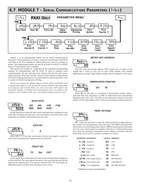
6.7 MODULE 7 - SERIAL COMMUNICATIONS PARAMETERS (�����)<br />
�<br />
���� �<br />
����<br />
BAUD RATE<br />
Set the baud rate to match the other serial communications equipment on the<br />
serial link. Normally, the baud rate is set to the highest value that all the serial<br />
equipment are capable of transmitting and receiving.<br />
�<br />
����<br />
�<br />
�<br />
DATA BIT<br />
Select either 7 or 8 bit data word lengths. Set the word length to match the<br />
other serial communications equipment on the serial link.<br />
�<br />
��� �<br />
���<br />
<strong>PAXI</strong> ONLY<br />
Module 7 is the programming module for the Serial Communications<br />
Parameters. These parameters are used to match the serial settings of the <strong>PAXI</strong><br />
with those of the host computer or other serial device, such as a terminal or<br />
printer. This programming module can only be accessed if an RS232 or RS485<br />
Serial Communications card is installed.<br />
This section also includes an explanation of the commands and formatting<br />
required for communicating with the <strong>PAXI</strong>. In order to establish serial<br />
communications, the user must have host software that can send and receive<br />
ASCII characters. <strong>Red</strong> <strong>Lion</strong>'s SFPAX software can be used for configuring the<br />
<strong>PAXI</strong> (See Ordering Information). For serial hardware and wiring details, refer<br />
to section 4.5 Serial Communication Wiring.<br />
This section replaces the bulletin shipped with the RS232 and RS485 serial<br />
communications plug-in cards. Discard the separate bulletin when using those<br />
serial plug-in cards with the <strong>PAXI</strong>. Also, this section does NOT apply to the<br />
DeviceNet, Modbus, or Profibus-DP communication cards. For details on the<br />
operation of the Fieldbus cards, refer to the bulletin shipped with each card.<br />
��� ��� ����<br />
���� ���� �����<br />
� �<br />
PARITY BIT<br />
�� ��� ����<br />
Set the parity bit to match that of the other serial communications equipment<br />
on the serial link. The meter ignores the parity when receiving data and sets the<br />
parity bit for outgoing data. If no parity is selected with 7 bit word length, an<br />
additional stop bit is used to force the frame size to 10 bits.<br />
PARAMETER MENU<br />
����<br />
24<br />
�<br />
�<br />
���� �<br />
��<br />
ABBREVIATED PRINTING<br />
Select �� for full print or Command T transmissions (meter address,<br />
parameter data and mnemonics) or ��� for abbreviated print transmissions<br />
(parameter data only). This will affect all the parameters selected in the print<br />
options. (If the meter address is 00, it will not be sent during a full transmission.)<br />
�<br />
���� �<br />
��<br />
��� �<br />
��<br />
METER UNIT ADDRESS<br />
�� to ��<br />
Enter the serial meter (node) address. With a single unit, an address is not<br />
needed and a value of zero can be used. With multiple units (RS485<br />
applications), a unique 2 digit address number must be assigned to each meter.<br />
��� ��<br />
PRINT OPTIONS<br />
��� - Enters the sub-menu to select the meter parameters to appear during a<br />
print request. For each parameter in the sub-menu, select ��� for that parameter<br />
information to be sent during a print request or �� for that parameter information<br />
not to be sent. A print request is sometimes referred to as a block print because<br />
more than one parameter information (meter address, parameter data and<br />
mnemonics) can be sent to a printer or computer as a block.<br />
PARAMETER DESCRIPTION<br />
FACTORY MNEMONIC<br />
����� Counter A ��� CTA<br />
����� Counter B �� CTB<br />
����� Counter C �� CTC<br />
���� Rate �� RTE<br />
���� Max. & Min. �� MIN MAX<br />
����� A B C Scale Factors �� SFA SFB SFC<br />
����� A B C Count Load �� LDA LDB LDC<br />
���� 1 2 3 4 Setpoints * �� SP1 SP2 SP3 SP4<br />
*Setpoints are plug-in card dependent.