PAXI PAXC PAXR Data Sheet/Manual PDF - Red Lion Controls
PAXI PAXC PAXR Data Sheet/Manual PDF - Red Lion Controls
PAXI PAXC PAXR Data Sheet/Manual PDF - Red Lion Controls

Create successful ePaper yourself
Turn your PDF publications into a flip-book with our unique Google optimized e-Paper software.
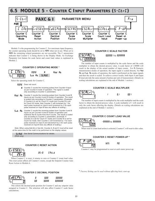
6.5 MODULE 5 - COUNTER C INPUT PARAMETERS (������)<br />
Module 5 is the programming for Counter C. For maximum input frequency,<br />
the counter operating mode should be set to ���� when not in use. When set to<br />
���� the remaining related parameters are not accessible. The C annunciator<br />
indicates that Counter C is being shown in the Display Mode. An Exchange<br />
Parameter List feature for scale factor and count load values is explained in<br />
Module 2.<br />
�<br />
�����<br />
�<br />
����<br />
������ �<br />
� ����<br />
COUNTER C OPERATING MODE *<br />
COUNTER C RESET ACTION<br />
When Counter C is reset, it returns to zero or Counter C count load value.<br />
This reset action affects all Counter C resets, except the Setpoint Counter Auto<br />
Reset Action in Module 6.<br />
������<br />
�<br />
�<br />
�<br />
����<br />
������<br />
�<br />
�����<br />
Select the operating mode for Counter C.<br />
����<br />
�<br />
������<br />
������<br />
�����<br />
Does not count.<br />
<strong>PAXC</strong> & I<br />
���� �����<br />
������<br />
Counter C counts the incoming pulses from Counter A input<br />
as per Counter A mode of operation. The signal is scaled<br />
only according to Counter C parameters.<br />
Counter C counts the incoming pulses from Counter A and B<br />
inputs as per Counter A and B modes of operation. The result<br />
is scaled only according to Counter C parameters. (Example:<br />
If Counter A is set for Count X1 mode and Counter B is set<br />
for Count X2 mode, then Counter C will increment by 1 for<br />
each pulse received on Input A and increment by 2 for each<br />
pulse received on Input B less any effects of scaling.)<br />
Counter C counts the incoming pulses from Counter A and B<br />
inputs as per Counter A and B modes of operation and<br />
subtracts the B counts from the A counts. The result is scaled<br />
only according to Counter C parameters. (Example: If<br />
Counter A is set for Count X1 mode and Counter B is set for<br />
Count X2 mode, then Counter C will increment by 1 for each<br />
pulse received on Input A and decrement by 2 for each pulse<br />
received on Input B less any effects of scaling.)<br />
Note: When using Add Ab or Sub Ab, Counter A, B and C must all be reset<br />
at the same time for the math to be performed on the display values.<br />
See Serial Communications for details.<br />
(<strong>PAXI</strong> only)<br />
COUNTER C DECIMAL POSITION<br />
� ���� ������<br />
��� ����� �������<br />
This selects the decimal point position for Counter C and any setpoint value<br />
assigned to Counter C. The selection will also affect Counter C scale factor<br />
calculations.<br />
PARAMETER MENU<br />
20<br />
������ �<br />
� �������<br />
������<br />
�<br />
COUNTER C SCALE MULTIPLIER<br />
�<br />
�<br />
The number of input counts is multiplied by the scale multiplier and the scale<br />
factor to obtain the desired process value. A scale multiplier of 1 will result in<br />
only the scale factor affecting the display. (Details on scaling calculations are<br />
explained at the end of Module 1 section.)<br />
������ �<br />
� ���<br />
COUNTER C COUNT LOAD VALUE<br />
When reset to count load action is selected, Counter C will reset to this value.<br />
������ �<br />
� ��<br />
COUNTER C SCALE FACTOR<br />
������� to �������<br />
The number of input counts is multiplied by the scale factor and the scale<br />
multiplier to obtain the desired process value. A scale factor of 1.00000 will<br />
result in the display of the actual number of input counts. For � (Numeric<br />
transmissions) modes of operation, the input signal is scaled directly. For ����<br />
�� and ������ modes of operation, the math is performed on the input signals<br />
and then the result is scaled. To achieve correct results, both Input A and Input<br />
B must provide the same amount of pulses per unit of measurement. (Details on<br />
scaling calculations are explained at the end of Module 1 section.)<br />
� ��� ����<br />
������ to ������<br />
COUNTER C RESET POWER-UP *<br />
��� ��<br />
Counter C may be programmed to reset at each meter power-up.<br />
* Factory Setting can be used without affecting basic start-up.