ultima ultra multi-temp ultra xl extra optima with standard micro prior ...
ultima ultra multi-temp ultra xl extra optima with standard micro prior ...
ultima ultra multi-temp ultra xl extra optima with standard micro prior ...
- No tags were found...

You also want an ePaper? Increase the reach of your titles
YUMPU automatically turns print PDFs into web optimized ePapers that Google loves.
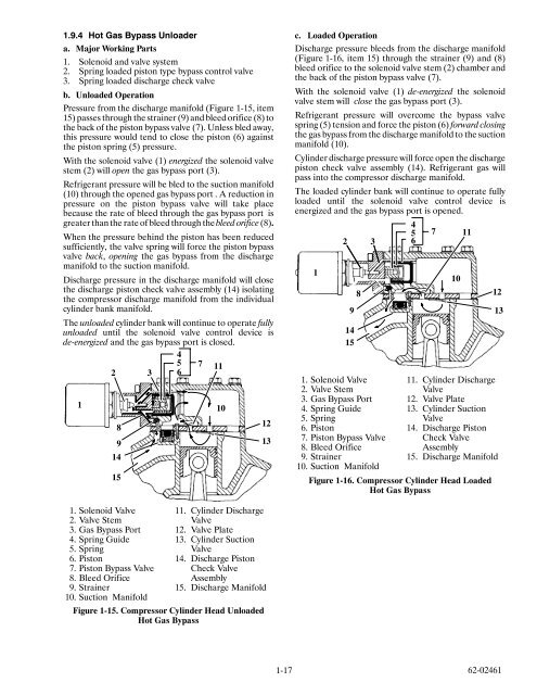
1.9.4 Hot Gas Bypass Unloadera. Major Working Parts1. Solenoid and valve system2. Spring loaded piston type bypass control valve3. Spring loaded discharge check valveb. Unloaded OperationPressure from the discharge manifold (Figure 1-15, item15) passes through the strainer (9) and bleed orifice (8) tothe back of the piston bypass valve (7). Unless bled away,this pressure would tend to close the piston (6) againstthe piston spring (5) pressure.With the solenoid valve (1) energized the solenoid valvestem (2) will open the gas bypass port (3).Refrigerant pressure will be bled to the suction manifold(10) through the opened gas bypass port . A reduction inpressure on the piston bypass valve will take placebecause the rate of bleed through the gas bypass port isgreater than the rate of bleed through the bleed orifice (8).When the pressure behind the piston has been reducedsufficiently, the valve spring will force the piston bypassvalve back, opening the gas bypass from the dischargemanifold to the suction manifold.Discharge pressure in the discharge manifold will closethe discharge piston check valve assembly (14) isolatingthe compressor discharge manifold from the individualcylinder bank manifold.The unloaded cylinder bank will continue to operate fullyunloaded until the solenoid valve control device isde-energized andthegasbypassportisclosed.45 7 112 3 618914151012139c. Loaded OperationDischarge pressure bleeds from the discharge manifold(Figure 1-16, item 15) through the strainer (9) and (8)bleed orifice to the solenoid valve stem (2) chamber andthe back of the piston bypass valve (7).With the solenoid valve (1) de-energized the solenoidvalve stem will close the gas bypass port (3).Refrigerant pressure will overcome the bypass valvespring (5) tension and force the piston (6) forward closingthe gas bypass from the discharge manifold to the suctionmanifold (10).Cylinder discharge pressure will force open the dischargepiston check valve assembly (14). Refrigerant gas willpass into the compressor discharge manifold.The loaded cylinder bank will continue to operate fullyloaded until the solenoid valve control device isenergized and the gas bypass port is opened.45 7 112 3 6114151. Solenoid Valve2. Valve Stem3.GasBypassPort4. Spring Guide5. Spring6. Piston7. Piston Bypass Valve8. Bleed Orifice9. Strainer10. Suction Manifold9810121311. Cylinder DischargeValve12. Valve Plate13. Cylinder SuctionValve14. Discharge PistonCheck ValveAssembly15. Discharge ManifoldFigure 1-16. Compressor Cylinder Head LoadedHot Gas Bypass1. Solenoid Valve2. Valve Stem3.GasBypassPort4. Spring Guide5. Spring6. Piston7. Piston Bypass Valve8. Bleed Orifice9. Strainer10. Suction Manifold11. Cylinder DischargeValve12. Valve Plate13. Cylinder SuctionValve14. Discharge PistonCheck ValveAssembly15. Discharge ManifoldFigure 1-15. Compressor Cylinder Head UnloadedHot Gas Bypass1-17 62-02461