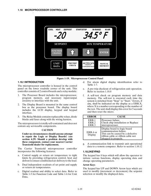
91.10 MICROPROCESSOR CONTROLLERCOOL HEAT DEFROST START/STOP IN-RANGE HI AIR-20 34.5° FSETPOINTBOX TEMPERATUREFUNCTIONCHANGEENTERUNITDATAPRETRIPCHECKAUTO S/SCONTINUOUSMANUALDEFROSTFigure 1-19. Microprocessor Control Panel1.10.1INTRODUCTIONThe <strong>micro</strong>processor controller is housed in the controlpanel on the lower roadside corner of the unit. Thiscontroller consists of 2 control boards and a relay module:1. The Processor Board includes the <strong>micro</strong>processor,program memory, and necessary input/outputcircuitry to interface <strong>with</strong> the unit.2. The Display Board is mounted in the same controlbox as the processor board. The display boardincludes the LCD display, keypad and keypadinterface.3. The Relay Module contains replaceable relays, diodeblocks and fuses along <strong>with</strong> the wiring harness.The <strong>micro</strong>processor is totally self-contained and does notcontain any serviceable components.CAUTIONUnder no circumstances should anyone at<strong>temp</strong>tto repair the Logic or Display Boards! (seesection 4.29) Should a problem develop <strong>with</strong>these component, contact your nearest CarrierTransicold dealer for replacement.The Carrier Transicold <strong>micro</strong>processor controllerincorporates the following features:a. Control supply or return air <strong>temp</strong>erature to tightlimits by providing refrigeration control, heat anddefrost to ensure conditioned air delivery to the load.b. Dual independent readouts of set point and supplyor return air <strong>temp</strong>eratures.c. Digital readout and ability to select data. Refer toTable 1-5 for Function Code and Table 1-6 for UnitData.d. For alarm digital display identification refer toTable 1-7.e. A pre-trip checkout of refrigeration unit operation.Refer to section 1.10.8f. A self-test check on program memory and datamemory. The self-test is executed each time thesystem is switched from “Stop” to “Start.” Errors, ifany, shall be indicated on the display as a ERR.X,where X is a number corresponding to the number ofthe test. The unit shall display this error for 5 secondsand then reset the <strong>micro</strong>.ERRORERR.1ERR.2ERR.3ERR.4 orDisplayCAUSEProcessor failureCheck chip installation or Replace<strong>micro</strong>processor.Display board to logic boardcommunication failure.This can be caused by a defectiveribbon cable or ribbon cable notplugged in properly.g. A communication link to transmit unit operationaldata to a remote computer. Refer to section 1.10.121.10.2KEYPADThe keypad has 8 keys which will allow the operator toinitiate various functions, display operating data andchange operating parameters.Arrow KeysThe keypad has UP and DOWN Arrow keys which areused to modify (increment or decrement) the setpointselection or modify the displayed data.1-19 62-02461
1.1.1 HEAT/COOL MODEEnter KeyThe ENTER key is used to accept a change in unitparameters or a change in setpoint.Manual Defrost KeyThe MANUAL DEFROST key is used to initiate adefrost cycle, given that the proper conditions are met(Refer section 1.10.10).Pretrip Check KeyThe PRETRIP CHECK key is used to initiate a pretripcycle, given that the proper conditions are met (Refer tosection 1.10.8).Auto Start/Stop Continuous KeyNOTEWith software revision 3.08 or 3.12 whenconfiguration CNF11 is “ON” and setpoint is 32to 42_ F (0 to 5.5_C) the unit is locked intocontinuous run. Start/Stop Continuous key isdisabled.The START/STOP CONTINUOUS key is used tochange the operating mode from “auto start/continuousrun” to “auto start/stop.” Each push of the key willalternate the operating modes. The operating status willbe stored in memory and will be retained through poweroutages. The digital display will indicate when stop/startis enabled (Also See Section 1.10.11).To start the unit in manual start mode, the START/STOPCONTINUOUS selection must be in continuous runmode.Function Change KeyThe FUNCTION CHANGE key is used to display theoperating parameters. Each time this key is pressed thedisplay will advance to the next parameter. This key, inconjunction <strong>with</strong> the UP/DOWN Arrow and ENTERkeys, will allow the user to change the parameters (SeeSection 1.10.5).Unit Data KeyThe UNIT DATA key is used to display the unit operatingdata. This key, in conjunction <strong>with</strong> the UP/DOWN Arrowkeys, will allow the user to display the unit’s operatingdata values (i.e, coolant <strong>temp</strong>erature, battery voltage,etc.) (See Section 1.10.6).1.10.3SETPOINTSetpoints of --- 22_Fto+86_F ( --- 30_Cto+30_C) may beentered via keypad. The controller always retains the lastentered setpoint in memory. If no setpoint is in memory(i.e., on initialstartup), the controller will lock out the runrelay and flash “SP” on the left hand display until a validsetpoint is entered.The setpoint may be changed up or down in wholenumbers until the desired setpoint is displayed. Thedisplay will flash to indicate that the setpoint readingbeing displayed is a non-entered value. Each time theUP/DOWN Arrow key is pressed, the 5 second displaytimer will be reset.Depressing the ENTER key will cause the new displayedsetpoint value to become active. If the display is flashingand the new value is not entered, after 5 seconds of nokeyboard activity, the display will revert back to theactive setpoint.1.10.4DIGITAL DISPLAYThe digital display has 9 digits. The default display issetpoint on the left and controlled air <strong>temp</strong>erature on theright. The readout is keypad selectable for Degrees C orDegrees F.Also digital displays are provided to indicate thefollowing modes: COOL, HEAT, DEFROST,IN-RANGE, HI AIR, START/STOP.On each power-up, the unit will display a Display Test for5 seconds then display the default reading.1.10.5FUNCTIONAL PARAMETERSNOTEIf configuration CNF11 is “ON” functionalparameters are lockout. The ability to changefunctional parameters from keypad are disabled.The functional parameters will control selectedoperating features of the unit. These parameters can bedisplayed by pressing the FUNCTION CHANGE key.All functional parameters are retained in memory. Thefollowing sections describe the list of functions which canbe modified via the keypad. A description of the functionwill be displayed on the left side <strong>with</strong> the correspondingdata on the right side. The function parameter list can bescrolled through by pressing the FUNCTION CHANGEkeyorbyusingtheUP/DOWNArrowkeys.WitheachFUNCTION CHANGE key push, the list will beadvanced one. If the function key is pressed and held forone second, the list will be advanced one item at a time.This list will be circular, meaning once the end of the list isreached the list will go to the first entry. While thefunctional parameter is displayed, the data can bechanged by pressing ENTER then pressing either the UPor DOWN Arrow keys. If the value is changed, thedisplayed data will then flash to indicate that the valuehas not been entered. If the new value is not entered in 5seconds, the display will revert back to the last enteredvalue. If the ENTER key is pressed, the display will stopflashing to indicate that the value has been entered. Thenew value will continue to be display for 5 seconds beforereverting back to the default display. Each time a key ispressed, the 5 second delay will be reset. To select adifferent functional parameter the FUNCTIONCHANGE key must be pressed first.Code Vs English MessagesThe description messages of the functional parameters,unit status and alarms can be displayed in English orCodes through this function selection. The two choiceswill be displayed as, ENGLISH or CODES. With thisparameter set to CODES, all display descriptions will beset to their code display. This parameter will not changedue to this selection. Refer to each section for thealternate display description.62-024611-20