CSI-F-10 User manual - Hydac
CSI-F-10 User manual - Hydac
CSI-F-10 User manual - Hydac
- No tags were found...

You also want an ePaper? Increase the reach of your titles
YUMPU automatically turns print PDFs into web optimized ePapers that Google loves.
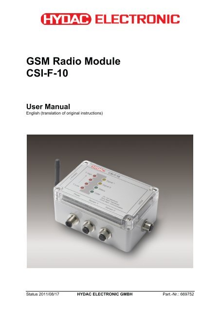
GSM Radio Module<strong>CSI</strong>-F-<strong>10</strong><strong>User</strong> ManualEnglish (translation of original instructions)Status 2011/08/17 HYDAC ELECTRONIC GMBH Part.-Nr.: 669752
GSM Radio Module <strong>CSI</strong>-F-<strong>10</strong> Page 2Status 2011/08/17 HYDAC ELECTRONIC GMBH Part.-Nr.: 669752
GSM Radio Module <strong>CSI</strong>-F-<strong>10</strong> Page 3Table of Contents1 General...........................................................................................................................91.1 Previous Knowledge..............................................................................................91.2 Structure of the Manual.........................................................................................91.3 Copyright Protection ...........................................................................................<strong>10</strong>1.4 Note on Warranty .................................................................................................<strong>10</strong>1.5 Declaration of Conformity .........................................................................<strong>10</strong>2 Safety ...........................................................................................................................112.1 General Safety Precautions ................................................................................112.2 Antenna.................................................................................................................122.3 Electronic Devices ...............................................................................................122.4 Potentially Explosive Substances / Locations..................................................122.5 Air travel ...............................................................................................................122.6 Safety-Related Applications ...............................................................................122.7 SIM card ................................................................................................................122.8 Loss / Theft of the SIM card or of the Device ....................................................123 Proper/Designated Use...............................................................................................133.1 Stand alone operation .........................................................................................143.2 Operation as GSM modem on a CMU <strong>10</strong>00........................................................144 Installation ...................................................................................................................154.1 Unpacking.............................................................................................................154.2 Installing the Unit.................................................................................................155 Setup and Function.....................................................................................................165.1 Display elements / Connections.........................................................................165.2 Pin connections ...................................................................................................175.3 Connection examples for sensors .....................................................................185.3.1 HYDACLab ® to Connection 1 and CS <strong>10</strong>00 to Connection 2 .........................185.3.2 AS <strong>10</strong>00 to Connection 1 and CS <strong>10</strong>00 to Connection 2................................195.3.3 HYDACLab ® and AS <strong>10</strong>00 to Connection 1....................................................205.4 Connection to Condition Monitoring Unit CMU <strong>10</strong>00 .......................................205.4 Connection to Condition Monitoring Unit CMU <strong>10</strong>00 .......................................216 Commissioning ...........................................................................................................226.1 Insert SIM card .....................................................................................................226.2 Program enable....................................................................................................236.3 Voltage supply with communication via direct connection with interfacemodule <strong>CSI</strong>-B-2 ...............................................................................................................246.3.1 Device Connection..........................................................................................256.3.2 Connection Setup ...........................................................................................26Status 2011/08/17 HYDAC ELECTRONIC GMBH Part.-Nr.: 669752
GSM Radio Module <strong>CSI</strong>-F-<strong>10</strong> Page 46.4 Voltage supply with communication via direct connection to Portable DataRecorder HMG 5<strong>10</strong>..........................................................................................................346.4.1 Device Connection..........................................................................................356.4.2 Connection Setup...............................................................................................356.4.2 Connection Setup ...........................................................................................366.5 Voltage supply with communication via GSM mobile radio connection(standard application) ....................................................................................................446.5.1 Device connection ..........................................................................................456.5.2 Connection Setup ...........................................................................................456.6 Voltage supply and communication via Condition Monitoring Unit CMU <strong>10</strong>00526.6.1 Device Connection..........................................................................................526.6.2 Connection Setup ...........................................................................................537 Configuration Using CMWIN PC Software ................................................................577.1 Actions..................................................................................................................577.1.1 Display Device Status ........................................................................................577.1.2 Display Device Information .............................................................................587.1.3 Display Measured Values ...............................................................................597.1.4 Setup ..............................................................................................................597.1.5 Managing Configurations................................................................................637.1.6 Set bus address..............................................................................................647.1.7 Managing sensor constellations .....................................................................647.1.8 Sending a text message .................................................................................657.2 Extras ....................................................................................................................667.2.1 Update Firmware ............................................................................................668 CM Editor .....................................................................................................................698.1 Menu Bar...............................................................................................................708.1.1 File ..................................................................................................................708.1.2 CM Program ...................................................................................................718.1.3 Grouping .........................................................................................................758.1.4 Device.............................................................................................................758.1.5 Sensor constellation .......................................................................................768.1.6 Extras..............................................................................................................788.2 Window Divisions ................................................................................................798.2.1 "Function Properties" Window ........................................................................798.2.2 "Function List" Window ...................................................................................798.2.3 "Linked Functions" Window ............................................................................798.2.4 "Functions" Window........................................................................................799 CM Program Functions...............................................................................................809.1 General Information Concerning Functions......................................................809.1.1 Inputs / Outputs ..............................................................................................809.1.2 Parameters .....................................................................................................819.2 Data Sources ........................................................................................................829.2.1 Numerical Constant ........................................................................................829.2.2 Measured value ..............................................................................................829.2.3 Digital Input.....................................................................................................829.2.4 Numerical Entry ..............................................................................................839.2.5 Boolean Entry .................................................................................................839.2.6 Time Sensor ...................................................................................................849.2.7 Clock Timer.....................................................................................................84Status 2011/08/17 HYDAC ELECTRONIC GMBH Part.-Nr.: 669752
GSM Radio Module <strong>CSI</strong>-F-<strong>10</strong> Page 59.2.8 Error Event......................................................................................................859.2.9 Boolean Constants .........................................................................................859.3 Numerical Calculations .......................................................................................869.3.1 Addition...........................................................................................................869.3.2 Subtraction......................................................................................................869.3.3 Multiplication ...................................................................................................869.3.4 Division ...........................................................................................................869.3.5 Division Remainder.........................................................................................879.3.6 Absolute Value................................................................................................879.3.7 Change of Algebraic Sign ...............................................................................879.3.8 Rounding ........................................................................................................879.3.9 Raising to a Higher Power ..............................................................................889.3.<strong>10</strong> Square Root....................................................................................................889.3.11 Power at Base e .............................................................................................889.3.12 Natural Logarithm ...........................................................................................889.3.13 Decade Logarithm ..........................................................................................899.3.14 Integral............................................................................................................899.3.15 Differential Quotient ........................................................................................909.4 Numerical Operations..........................................................................................919.4.1 Minimum .........................................................................................................919.4.2 Maximum ........................................................................................................919.4.3 Limit ................................................................................................................919.4.4 If - then - else..................................................................................................919.4.5 Median Value..................................................................................................929.4.6 Note Value ......................................................................................................929.4.7 Note Minimum.................................................................................................929.4.8 Note Maximum................................................................................................939.4.9 Tabular Value .................................................................................................939.4.<strong>10</strong> Tabular Index..................................................................................................949.4.11 Characteristic Curve .......................................................................................949.4.12 Ramp ..............................................................................................................959.5 Counting Functions .............................................................................................969.5.1 Count Pulses ..................................................................................................969.5.2 Stop Watch .....................................................................................................969.6 Numerical Conditions..........................................................................................979.6.1 Equals.............................................................................................................979.6.2 Does not Equal ...............................................................................................979.6.3 Greater than....................................................................................................989.6.4 Greater than or Equal to .................................................................................989.6.5 Less than ........................................................................................................989.6.6 Less than or Equal to......................................................................................999.6.7 Within..............................................................................................................999.6.8 Outside ...........................................................................................................999.7 Boolean Links ....................................................................................................<strong>10</strong>09.7.1 Not ................................................................................................................<strong>10</strong>09.7.2 And ...............................................................................................................<strong>10</strong>09.7.3 Not - And.......................................................................................................<strong>10</strong>09.7.4 Or..................................................................................................................<strong>10</strong>19.7.5 Not - Or .........................................................................................................<strong>10</strong>19.7.6 Exclusive Or..................................................................................................<strong>10</strong>29.7.7 Not Exclusive Or ...........................................................................................<strong>10</strong>29.8 Other Boolean Operations ................................................................................<strong>10</strong>39.8.1 Note Switching Status...................................................................................<strong>10</strong>3Status 2011/08/17 HYDAC ELECTRONIC GMBH Part.-Nr.: 669752
GSM Radio Module <strong>CSI</strong>-F-<strong>10</strong> Page 69.8.2 Switching Delay ............................................................................................<strong>10</strong>39.8.3 T - Flipflop.....................................................................................................<strong>10</strong>49.8.4 Mono Flop.....................................................................................................<strong>10</strong>49.8.5 RS - Flipflop ..................................................................................................<strong>10</strong>59.8.6 Pulse Generation ..........................................................................................<strong>10</strong>59.9 Result Values .....................................................................................................<strong>10</strong>69.9.1 Numerical Output Value................................................................................<strong>10</strong>69.9.2 Boolean Output Value...................................................................................<strong>10</strong>79.<strong>10</strong> Actions................................................................................................................<strong>10</strong>89.<strong>10</strong>.1 Setting Switching Output ..............................................................................<strong>10</strong>89.<strong>10</strong>.2 Switch on LED ..............................................................................................<strong>10</strong>89.<strong>10</strong>.3 Send SMS.....................................................................................................<strong>10</strong>89.11 Other ...................................................................................................................<strong>10</strong>99.11.1 Comment ......................................................................................................<strong>10</strong>9<strong>10</strong> Error Messages CM Program Compilation..........................................................1<strong>10</strong><strong>10</strong>.1 Overriding Error Messages...............................................................................111<strong>10</strong>.1.1 Function not Available in this Mode ..............................................................111<strong>10</strong>.2 Error Messages with Data Sources..................................................................111<strong>10</strong>.2.1 Invalid Channel Setting.................................................................................111<strong>10</strong>.2.2 Duplicate Channel Name..............................................................................111<strong>10</strong>.2.3 Invalid Digital Input .......................................................................................111<strong>10</strong>.2.4 Duplicate Digital Input...................................................................................111<strong>10</strong>.2.5 Too many Boolean Input Fields ....................................................................111<strong>10</strong>.2.6 No Inscription for Boolean Input ...................................................................111<strong>10</strong>.2.7 Duplicate Inscription for Boolean Inputs .......................................................111<strong>10</strong>.2.8 Too Many Numerical Input Values................................................................111<strong>10</strong>.2.9 No Inscription for Numerical Input ................................................................112<strong>10</strong>.2.<strong>10</strong> Duplicate Inscription for Numerical Input ..................................................112<strong>10</strong>.2.11 Duplicate Error Source..............................................................................112<strong>10</strong>.3 Error Messages for Operations/Conditions.....................................................112<strong>10</strong>.3.1 Upper and Lower Measured Value Limits too Close to one another ............112<strong>10</strong>.3.2 Measured Value Limits Outside the Range of -30000 to 30000 ...................112<strong>10</strong>.3.3 Lower Measured Value Limit Greater than Upper Measurement Value Limit112<strong>10</strong>.4 Error Messages with Result Values/Actions ...................................................112<strong>10</strong>.4.1 Invalid Output LED Selected.........................................................................112<strong>10</strong>.4.2 Duplicate Use of Output LED........................................................................112<strong>10</strong>.4.3 Invalid Digital Output.....................................................................................113<strong>10</strong>.4.4 Duplicate Digital Ouput .................................................................................113<strong>10</strong>.4.5 Too Many Boolean Output Fields .................................................................113<strong>10</strong>.4.6 Duplicate Boolean Output Field ....................................................................113<strong>10</strong>.4.7 The Bit Number Must Be a Figure between 0 and 14...................................113<strong>10</strong>.4.8 Too Many Numerical Output Fields ..............................................................113<strong>10</strong>.4.9 Duplicate Numerical Output Field .................................................................113<strong>10</strong>.4.<strong>10</strong> Message and telephone number too long.................................................11311 Specifications ........................................................................................................11411.1 Power Supply .....................................................................................................11411.2 Sensor Inputs (5 pole female connection "Sensor 1", 8 pole femaleconnection "Sensor 2")................................................................................................11411.3 Logic measurement channels ..........................................................................114Status 2011/08/17 HYDAC ELECTRONIC GMBH Part.-Nr.: 669752
GSM Radio Module <strong>CSI</strong>-F-<strong>10</strong> Page 711.4 Digital Inputs and Outputs (8 pole female connection "In/Out")...................11411.5 Interfaces ............................................................................................................11411.6 Cycle Time ..........................................................................................................11511.7 Operating and Ambient Conditions .................................................................11511.8 Dimensions and Weight: ...................................................................................11511.9 Technical Standards..........................................................................................11511.<strong>10</strong> Items supplied ................................................................................................11511.11 Maintenance and cleaning.............................................................................11511.12 Recycling and Disposal .................................................................................11612 Ordering Details.....................................................................................................11713 Exclusion of liability..............................................................................................11714 Accessories ...........................................................................................................118Status 2011/08/17 HYDAC ELECTRONIC GMBH Part.-Nr.: 669752
GSM Radio Module <strong>CSI</strong>-F-<strong>10</strong> Page 8PrefaceWe have compiled the most important instructions for the operation andmaintenance of our product for you, its user, in this documentation.It will acquaint you with the product and assist you in using it as intended inan optimal manner.Keep it in the vicinity of the product so it is always available.Note that the information on the unit's engineering contained in thedocumentation was that available at the time of publication. There may bedeviations in technical details, figures, and dimensions as a result.If you discover errors while reading the documentation or have additionalsuggestions or notes, contact us at:HYDAC ELECTRONIC GMBHTechnical DocumentationHauptstraße 2766128 Saarbrücken-Germany-Tel: +49(0)6897 / 509-01Fax: +49(0)6897 / 509-1726Email: electronic@hydac.comThe editorial board would welcome your contributions.„Putting experience into practice“Status 2011/08/17 HYDAC ELECTRONIC GMBH Part.-Nr.: 669752
GSM Radio Module <strong>CSI</strong>-F-<strong>10</strong> Page 91 GeneralThis <strong>manual</strong> is a constituent part of the device. It contains texts and graphicsconcerning the correct handling of the product and must be read before installation,assembly and the operation of the device.The <strong>manual</strong> offers information concerning the safe operation, installation andprogramming of the GSM radio module <strong>CSI</strong>-F-<strong>10</strong>. It is aimed at engineers,programmers, fitters and maintenance personnel with a general knowledge ofautomation technology.By using this <strong>manual</strong> as recommended, you will ensure that the <strong>CSI</strong>-F-<strong>10</strong> is put intoeffective and safe operation as quickly as possible. The following questions arecovered in the next few points:• What prior knowledge must one have in order to be able to program the<strong>CSI</strong>-F-<strong>10</strong>?• How is this <strong>manual</strong> structured?• What's the best way to use this <strong>manual</strong>?• What information can I find in this <strong>manual</strong>?1.1 Previous KnowledgeNo special previous knowledge is required for using and programming the <strong>CSI</strong>-F-<strong>10</strong>GSM radio module.A general knowledge of automation technology or memory-programmable controllersand a knowledge of control technology or PLC programming will however beadvantageous and speed up the familiarization period.1.2 Structure of the ManualWe have integrated a variety of different Help functions to make it easier to use this<strong>manual</strong>. Please consult the Table of Contents to find a specific topic. A brief overviewis provided at the beginning of each Chapter listing the contents of that particularChapter.Selective ReadingYou will find notes in the side margins that make it easier to find particular sections.Pictograms and markings are also given, and these are explained below.Furthermore, this <strong>manual</strong> also contains instructions regarding personal safety and theavoidance of property damage that must be observed. The instructions are highlightedby a Warning symbol and displayed as follows, depending on the seriousness of thehazard:Status 2011/08/17 HYDAC ELECTRONIC GMBH Part.-Nr.: 669752
GSM Radio Module <strong>CSI</strong>-F-<strong>10</strong> Page <strong>10</strong>Dangermeans that death, severe bodily injury or considerable property damage will occur if therespective precautionary measures are not implemented.Warningmeans that death, severe bodily injury or considerable property damage could occur ifthe respective precautionary measures are not implemented.Cautionmeans that some non-severe bodily injury or property damage could occur if therespective precautionary measures are not implemented.Attentionmeans that an unwanted event or condition could occur if the respective instruction isnot followed.Notemeans an important piece of information about the product, its handling or a part of thedocumentation to which particular attention should be paid.In the event that several hazard levels occur simultaneously, it is always the highestlevel warning notice that is used. If the warning triangle warns against possiblepersonal injury, then a warning against possible property damage can also be attachedto the same warning notice.1.3 Copyright ProtectionThe dissemination and/or reproduction of this document, as well as the exploitation andcommunication of its content, is not permitted unless specifically authorized.Contraventions are liable to compensation. All rights reserved.1.4 Note on WarrantyThis <strong>manual</strong> was compiled with the greatest possible care. Nevertheless, errors ordeviations cannot be excluded, and for this reason we assume no responsibility for thecomplete accuracy of the content.In view of the fact that, despite intensive endeavors, errors can never be completelyavoided, we welcome tips and suggestions for improvement at any time.1.5 Declaration of ConformityThis product is labelled with the CE Marking and thus is in compliance with currentGerman marketing authorization regulations and European standards.As a consequence, compliance with the current regulations on electromagneticcompatibility and the safety provisions of the Low-Voltage Directive is ensured.This product complies with the provisions of the following European Directives:EN 6<strong>10</strong>00-6-1 / 2 / 3 / 4 and the R&TTE Directive 1999/5/EC.Status 2011/08/17 HYDAC ELECTRONIC GMBH Part.-Nr.: 669752
GSM Radio Module <strong>CSI</strong>-F-<strong>10</strong> Page 112 Safety2.1 General Safety PrecautionsFollow the specifications contained in this description. Non-observance of theinstructions, operation in applications other than those outlined below, incorrectinstallation/assembly or incorrect handling of the product can be severely detrimental tothe safety of personnel and systems/machines and will invalidate warranty and liabilityclaims.Immediately after unpacking, check that all items have been supplied correctly and thatthe device is in perfect condition.The device may not be commissioned or operated except by qualified personnel whocan be regarded as being "competent" as defined in the EMC and Low VoltageDirectives.Qualified personnel are individuals who are authorized to operate, ground and labeldevices, systems and electrical circuits in accordance with safety standards.All relevant and generally recognized safety requirements must be complied with.If the voltage supply to the device is not provided by an on-board electrical system(24 V battery operation), then care must be taken to ensure that the external voltage isgenerated and routed in accordance with the criteria for safe low voltage (SELV[Separated Extra Low Voltage] pursuant to EN 60950), in view of the fact that this isavailable for supplying the connected control system, sensor system and actuatingelements without any other additional measures being implemented.The wiring of all of the signals connected with the SELV circuit in the device must alsomeet the SELV criteria (safe extra low voltage with protective separation from otherelectrical circuits).If the SELV voltage supplied is grounded externally (PELV according to EN 50178),then responsibility for this and for compliance with any applicable national installationregulations rests with the operator.All of the statements made in this <strong>manual</strong> refer to devices which are not grounded interms of the SELV voltage.Generally speaking, DIN VDE 0<strong>10</strong>0 Part 4<strong>10</strong> must be observed for the supply voltage.Only the particular signals which are specified in the Technical Data and/or on thedevice label may be supplied to the connections and only authorized HYDACELECTRONIC GMBH accessory components may be connected to them.In accordance with the following technical specifications, the device can be operated ina wide range of ambient temperatures. Due to the additional self-heating of the device,high contact temperatures may develop on the housing in hot environments.In the event of faults or if anything is unclear, please contact your nearest HYDACrepresentative. Tampering with the unit can have severe consequences for personaland system safety. These are not permitted and will invalidate all liability and warrantyclaims.Fault investigation and repairs may only be carried out by HYDAC SERVICE GMBHCustomer Service Department.Status 2011/08/17 HYDAC ELECTRONIC GMBH Part.-Nr.: 669752
GSM Radio Module <strong>CSI</strong>-F-<strong>10</strong> Page 122.2 AntennaOperating the radio module without attaching the antenna or when the antenna isfaulty, can damage the unit.2.3 Electronic DevicesOperating the <strong>CSI</strong>-F-<strong>10</strong> can under certain circumstances adversely affect thefunctioning of other electronic devices if they are not screened correctly.Please contact the manufacturer of the particular device in the event of failure.Do not operate the GSM radio module <strong>CSI</strong>-F-<strong>10</strong> in the vicinity of medical equipment!2.4 Potentially Explosive Substances / LocationsThe radio modules in the series <strong>CSI</strong>-F-<strong>10</strong> may not be operated in the vicinity of fuelstations, fuel depots, chemical plants or blasting work.When operated in off-highway vehicles, construction, agricultural or other machinery,no flammable gases, fluids or other explosive substances may be transported or storedin the parts of the vehicles in which the radio module is mounted.2.5 Air travelThe GSM radio module <strong>CSI</strong>-F-<strong>10</strong> must not be operated on board aeroplanes,helicopters or other aircraft.Operation in one of the above-mentioned aircraft, would adversely affect thenavigation, control and / or communication systems.Contraventions can result in legal proceedings against offenders.2.6 Safety-Related ApplicationsDo not install the GSM radio module <strong>CSI</strong>-F-<strong>10</strong> for safety-related applications (to DINEN ISO 13849-1 Functional Safety).2.7 SIM cardPlease note that a SIM card is required to operate each <strong>CSI</strong>-F-<strong>10</strong>. You can obtain SIMcards from the usual providers, such as T-Mobile, VODAFONE or E-Plus.Deactivate the mailbox function and the caller ID restriction.2.8 Loss / Theft of the SIM card or of the DeviceIn order to prevent fraudulent use, inform your network operator immediately if the SIMcard or the radio module is lost or stolen.Status 2011/08/17 HYDAC ELECTRONIC GMBH Part.-Nr.: 669752
GSM Radio Module <strong>CSI</strong>-F-<strong>10</strong> Page 133 Proper/Designated UseThe GSM radio module <strong>CSI</strong>-F-<strong>10</strong> is an electronic unit with universal application fortransferring data and digital signals via the GSM mobile radio network. The device canbe used in both stand-alone operation and as a GSM modem on a CMU <strong>10</strong>00 (HYDACCondition Monitoring Unit).A maximum of two HYDAC SMART sensors with HSI interface (automatic sensorrecognition), e.g. HYDACLab ® , AS <strong>10</strong>00 or CS <strong>10</strong>00, can be connected to its inputconnections.In addition, several other system statuses can be monitored via the four integral digitalinputs and transmitted in binary using the two integral digital outputs. The device canalso access the machine / system being monitored directly via these digital outputs.The sensor values, statuses etc can be requested by SMS/text. To do this an SMS withthe text "Values" must be sent to the <strong>CSI</strong>-F-<strong>10</strong>. The device then automatically sendsone or several reply text messages containing all the sensor values and additionalinformation available.Note!The GSM radio module <strong>CSI</strong>-F-<strong>10</strong> only replies or accepts data connections if thetelephone number of the sender is visible and has been registered in the authorizedtelephone numbers in the <strong>CSI</strong>-F-<strong>10</strong> (see Chap. 7.1.4).The <strong>CSI</strong>-F-<strong>10</strong> devices are designed for use in difficult conditions. They are thereforesuitable for direct installation in machines and systems and in stationary and mobileoff-highway applications (not for public road and rail transport!).The inputs and outputs are designed to a special specification for such applications.Integrated hardware and software functions (operating system) provide a greater levelof protection for the machine.Examples of possible applications:• Remote parameterization of HYDAC Condition Monitoring units and sensors instationary or mobile machines and systems• Remote diagnostics of system conditions• Transmission of alarm messages as SMS• Read-outs of operating conditions from machines that are running• ...Warning!The device may be used only for the types of applications specified in the <strong>manual</strong> andonly in connection with accessory components authorized by HYDAC ELECTRONICGMBH. The trouble-free and safe operation of the product is contingent on propertransport; storage, setup and installation; and on careful operation and maintenance.Status 2011/08/17 HYDAC ELECTRONIC GMBH Part.-Nr.: 669752
GSM Radio Module <strong>CSI</strong>-F-<strong>10</strong> Page 14The two basic operating modes available for using the GSM radio module <strong>CSI</strong>-F-<strong>10</strong> aredescribed below:3.1 Stand alone operationThe <strong>CSI</strong>-F-<strong>10</strong> transmits the measured values and additional information of theconnected sensors directly and without processing them (passive mode) or monitorsand processes the input signals with a "CM program" stored in the unit (active mode).The application software for the active mode, das "CM Program", can be readilygenerated by the user using the "CM Editor" on a PC. The "CM Editor" is a componentpart of the HYDAC PC software "CMWIN", version 3.0 or higher.In the above-mentioned "CM program" you define in detail which data will be monitoredand how, and when and which type of message should occur.For example, once a parameterized limit has been exceeded, an alarm SMS can besent or a switch output can be set. All texts and telephone numbers for the relevantSMS must be stored in the CM program by the user.Note!All of the programming procedures and software functions subsequently described inthis documentation refer to the "CM Editor" in accordance with IEC 61131.The operator is responsible for the safe and application-appropriate functioning of theCM Programs that he or she generates.3.2 Operation as GSM modem on a CMU <strong>10</strong>00When using the unit as a GSM modem, the <strong>CSI</strong>-F-<strong>10</strong> must be connected via HSI signal(HYDAC sensor interface) to the CMU <strong>10</strong>00. The CMU <strong>10</strong>00 is in this case the "busmaster" and controls the radio module.In this operating mode, one or more sensors are monitored by the CMU <strong>10</strong>00. Theirinput signals are evaluated according to the CM program stored in the CMU <strong>10</strong>00 andprocessed.The resulting data and / or messages are transmitted from the CMU <strong>10</strong>00 via HSIinterface to the GSM radio module. The radio module transfers this data and / ormessages controlled by the CMU <strong>10</strong>00 directly by SMS.The SMS text and the receiving telephone number are stored in the CM program in theCMU <strong>10</strong>00 for this purpose.Status 2011/08/17 HYDAC ELECTRONIC GMBH Part.-Nr.: 669752
GSM Radio Module <strong>CSI</strong>-F-<strong>10</strong> Page 154 Installation4.1 UnpackingThe <strong>CSI</strong>-F-<strong>10</strong> is supplied in a cardboard box. When taking delivery and whenunpacking the unit, check it for transit damage and report any damage to the carrierimmediately.4.2 Installing the UnitOnly fit the unit in locations where the radio module can be operated without risk (seeChapter 2. Safety).• When you are planning the layout for your system, allow sufficient spaceunderneath the unit and to the right of the unit, and distance between it and otherdevices for cabling the peripherals and for connecting the communication cable.• Mount the GSM radio module using the mounting holes provided in the lower partof the housing. To do this, the housing cover of the radio module must beremoved.• When installing in off-highway vehicles, construction & agricultural machinery etc,avoid placing near to fuel tanks, tanks containing explosive substances orelectronic components which are inadequately screened.• Do not fit the antenna in enclosed metal constructions, such as a driver's consoleor cab, or similar (Faraday screening effect).• Do not lengthen or shorten any antenna lines.Note!The condition for a stable GSM mobile radio connection is a good antenna signal.If problems occur, change the position of the antenna or the mobile device. Also, if theantenna plug is not tightly fitted this will cause a loss of signal!The antenna connection must be protected from humidity and moisture.Status 2011/08/17 HYDAC ELECTRONIC GMBH Part.-Nr.: 669752
GSM Radio Module <strong>CSI</strong>-F-<strong>10</strong> Page 165 Setup and FunctionThe GSM radio module <strong>CSI</strong>-F-<strong>10</strong> is an electronic device with universal applications fortransmitting data and digital signals over the GSM mobile radio network.A maximum of two HYDAC SMART sensors with HSI interface (automatic sensorrecognition), e.g. HYDACLab ® , AS <strong>10</strong>00 or CS <strong>10</strong>00, can be connected to its inputconnections.5.1 Display elements / Connections4x LED red: 2x LED yellow: 2x LED green:reception strength user configuration status sensor recognitionGSM network via CM program GSM activityGSM antennaIn / Out socket:Dig. Input 1, 2, 3, 4Dig. Output 1, 2with supplyPower connection: Sensor 1: Sensor 2:voltage supply. AS <strong>10</strong>00 / CS <strong>10</strong>00HSI-Master HYDACLab ®HSI + supply HSI + supplyLED Color Condition MeaningHighredOnLowAll OffOnGSM green Rapid flashingSlow flashingOnStatus green FlashingOffSignal 1 yellow On / OffSignal 2 yellow On / Off4 LEDs: reception strength > 75 %3 LEDs: reception strength > 50 %2 LEDs: reception strength > 25 %1 LED: reception strength < 25 %No receptionNot registeredCommunicationRegisteredMin. 1 sensor recognisedPC connection activeNo sensor recognisedFunction according to CM program(programmable user application)In the initialization phase (approx. <strong>10</strong> sec.) the LEDs will not indicate any definedcondition.Status 2011/08/17 HYDAC ELECTRONIC GMBH Part.-Nr.: 669752
GSM Radio Module <strong>CSI</strong>-F-<strong>10</strong> Page 175.2 Pin connectionsPlug Pin Function I/OPower1 +U B (in)2 n.c.3 0 V4 n.c.5 HSIPlug Pin Function I/OSensor 1(AS <strong>10</strong>00HLB <strong>10</strong>00)1 +U B (out)2 n.c.3 n.c.4 0 V5 HSI IN / OUTPlug Pin Function I/OSensor 2(CS <strong>10</strong>00)1 +U B (out)2 n.c.3 0 V4 n.c.5 HSI IN / OUT6 n.c.7 n.c.8 n.c.Plug Pin Function I/OIn / Out1 Digital Out 1 OUT2 Digital In 1 IN3 +U B (out)4 Digital In 2 IN5 0 V6 Digital In 3 IN7 Digital In 4 IN8 Digital Out 2 OUTStatus 2011/08/17 HYDAC ELECTRONIC GMBH Part.-Nr.: 669752
GSM Radio Module <strong>CSI</strong>-F-<strong>10</strong> Page 185.3 Connection examples for sensorsWarning!The total length of the connected sensor cables (Sensor 1 + Sensor 2) may not exceedmax. 40 m. If this 40 m length is exceeded, there can be problems with the HSI signaltransmission.5.3.1 HYDACLab ® to Connection 1 and CS <strong>10</strong>00 to Connection 2In this case, only voltagesupply for CS <strong>10</strong>00!ZBE 38Voltage supply / HSIsee Chap. 6.3 to 6.68 pole, max. 30m5 pole, max. 30m5 pole, max. 30mA ZBE 26 BIn totalmax. 40mA ZBE 41 BHSI Address "a"HSI Address "b"Note!Connection "A" of the ZBE 26 (blue Y adaptor) must be sealed using the protective capprovided, to protect it from dirt and moisture!Status 2011/08/17 HYDAC ELECTRONIC GMBH Part.-Nr.: 669752
GSM Radio Module <strong>CSI</strong>-F-<strong>10</strong> Page 195.3.2 AS <strong>10</strong>00 to Connection 1 and CS <strong>10</strong>00 to Connection 2ZBE 38In this case, only voltagesupply for CS <strong>10</strong>00!Voltage supply / HSIsee Chap. 6.3 to 6.68 pole, max. 30m5 pole, max. 30mIn totalmax. 40m5 pole, max. 30mZBE 36A ZBE 41 BHSI Address "a"HSI Address "b"Status 2011/08/17 HYDAC ELECTRONIC GMBH Part.-Nr.: 669752
GSM Radio Module <strong>CSI</strong>-F-<strong>10</strong> Page 205.3.3 HYDACLab ® and AS <strong>10</strong>00 to Connection 1Voltage supply / HSIsee Chap. 6.3 to 6.6ZBE 38in totalmax. 40m5 pole, max. 30m5 pole, max. 30mA ZBE 26 BZBE 36A ZBE ZBE 26 41 BHSI Address "a"HSI Address "b"Note!Regardless of the type of constellation, a maximum of 2 SMART sensors can beconnected to the <strong>CSI</strong>-F-<strong>10</strong> and evaluated by the device. The connected sensors mustalready be addressed using the HSI addresses "a" and "b".In other words, each sensor must be addressed before connecting to the <strong>CSI</strong>-F-<strong>10</strong>, forexample using an HMG 3000.5.4Status 2011/08/17 HYDAC ELECTRONIC GMBH Part.-Nr.: 669752
GSM Radio Module <strong>CSI</strong>-F-<strong>10</strong> Page 21Connection to Condition Monitoring Unit CMU <strong>10</strong>00max. 30m5 4 3 2 1+U B 0VHSI18..35 V DC / 3.5 ANote!For this connection option, the CMU <strong>10</strong>00 can either be configured via the <strong>CSI</strong>-F-<strong>10</strong>, orthe <strong>CSI</strong>-F-<strong>10</strong> can be configured via the CMU <strong>10</strong>00.In addition the <strong>CSI</strong>-F-<strong>10</strong> acts as the GSM modem to the CMU <strong>10</strong>00, to forward dataand / or messages sent from this unit (see Chap. 3.2.).Similar to the SMART sensors, the CMU <strong>10</strong>00 must also be addressed with an HSIaddress ("a" or "b") before connecting to the <strong>CSI</strong>-F-<strong>10</strong>.Status 2011/08/17 HYDAC ELECTRONIC GMBH Part.-Nr.: 669752
GSM Radio Module <strong>CSI</strong>-F-<strong>10</strong> Page 226 CommissioningNote!In order to be able to communicate later with the <strong>CSI</strong>-F-<strong>10</strong> via GSM mobile radio, thismust first be configured. This means that the mobile phone numbers which areauthorized for access must be stored in the <strong>CSI</strong>-F-<strong>10</strong> and appropriate permissionsassigned. In order to configure the GSM radio module <strong>CSI</strong>-F-<strong>10</strong>, first connect directlywith the GSM radio module <strong>CSI</strong>-F-<strong>10</strong> (via <strong>CSI</strong>-B-2, HMG 5<strong>10</strong> or CMU <strong>10</strong>00).►See Chapter 6.3, 6.4 and 6.5!6.1 Insert SIM cardWarning!Only ever insert or remove the SIM card when voltage supply is disconnected.• Remove the housing cover by unscrewing the 4 mounting screws.• Press on the catch "PUSH OPEN" and lift the SIM card holder to the right.• Push the SIM card into the holder as per the diagram.• Lift the holder again to the left, until it snaps back into the catch• Replace the housing cover back onto the lower part of the housing.The GSM radio module <strong>CSI</strong>-F-<strong>10</strong> can only operate as such with a valid SIM card. Thiscard and the pin number for it can be obtained from your network operator or GSMservice provider.For the direct transfer of data (online mode) you will need a SIM card which supportsthe GSM data service and which is enabled for this.(The GSM data service is not available in all countries and is not supported by all mobile phone operators.Please contact your service provider for further information. This information does not apply to textmessages!)Use of pre-paid SIM cards!Pre-paid SIM cards have a limited validity and limited credit. If the credit is used up orthe validity has expired, the function of the GSM radio module will no longer beguaranteed!‣ Top up your pre-paid SIM card in good time!Warning!SIM cards and their contacts can easily be damaged by scratching or bending. Whenhandling the card, avoid placing any force on or touching the contacts.Status 2011/08/17 HYDAC ELECTRONIC GMBH Part.-Nr.: 669752
GSM Radio Module <strong>CSI</strong>-F-<strong>10</strong> Page 23PIN deactivationIf the PIN number is not input correctly or in full, during commissioning the SIM cardcan be blocked.We recommend therefore that the PIN of the SIM card is deactivated. To deactivate thePIN code, place the SIM card in a mobile telephone and follow the device menu todeactivate the PIN request.Deactivating call forwarding / mailboxDeactivate all the call forwards and the mailbox functions of the SIM card to be used toachieve efficient accessibility with the <strong>CSI</strong>-F-<strong>10</strong> GSM radio module.6.2 Program enableProgram enable is effected via a micro-switch on the upper right edge of the board.Providing the switch is set to ON you can configure the <strong>CSI</strong>-F-<strong>10</strong>, make settings,transfer CM programs etc via a PC connection, irrespective of the permissionsspecified in the settings (see Chapter 7.1.4).• Remove the housing cover.• Push the switch to the right to "ON" to switch on the program enable.• Push the switch to the left to "OFF" to switch off the program enable.Warning!When the programming enable is switched off (switch set to 'OFF') no settings,program changes or other changes to the device configuration can be made via a PCconnection.Status 2011/08/17 HYDAC ELECTRONIC GMBH Part.-Nr.: 669752
GSM Radio Module <strong>CSI</strong>-F-<strong>10</strong> Page 246.3 Voltage supply with communication via directconnection with interface module <strong>CSI</strong>-B-2If a GSM radio module is connected to the PC via an adaptor such as the HYDACinterface module <strong>CSI</strong>-B-2, then the GSM radio module has the HSI address "Busmaster".If further sensors are connected to the <strong>CSI</strong>-F-<strong>10</strong>, these must be addressed with thenormal HSI address "a" or "b".In order to be able to communicate with the GSM radio module or with the sensorsconnected to it, the <strong>CSI</strong>-F-<strong>10</strong> must first be addressed using the HSI address "busmaster". This means the GSM modem is switched into Slave mode and the PC worksas the bus master.If afterwards a sensor connected to the <strong>CSI</strong>-F-<strong>10</strong> is to be addressed, the connectionbetween PC and GSM radio module must be disconnected. In CMWIN a queryappears asking whether the master which was previously connected to the slave (the<strong>CSI</strong>-F-<strong>10</strong>) should again be the master. This query must be answered with "No".After this, the connection to the sensors which are connected to the <strong>CSI</strong>-F-<strong>10</strong> can beset up using the usual HSI addresses "a" or "b".GSM radio module<strong>CSI</strong>-F-<strong>10</strong>(address 'bus master')Sensor (Address a)PCRS232RS485<strong>CSI</strong>-B-2HSISensor (Address b)Warning!If the GSM radio module is directly connected to the PC and CMWIN via the HYDACinterface module <strong>CSI</strong>-B-2 via HSI, no measured values are output and no new sensorswill be recognized.In other words, if a sensor had been connected to the GSM radio module before theconnection setup, only those measured values which have been output directly prior tothe connection setup appear in CMWIN.Furthermore, new sensors must be connected to the <strong>CSI</strong>-F-<strong>10</strong> before the connectionsetup because otherwise they will not be recognized.Status 2011/08/17 HYDAC ELECTRONIC GMBH Part.-Nr.: 669752
+U BGNDGSM Radio Module <strong>CSI</strong>-F-<strong>10</strong> Page 256.3.1 Device Connection• Connect the RS232 serial interface of your PC with the 9-pin SUB-D socket ofthe HYDAC interface module <strong>CSI</strong>-B-2 via a corresponding data cable (orRS485 via terminal block).• Connect the <strong>CSI</strong>-F-<strong>10</strong> to the <strong>CSI</strong>-B-2 via the HSI connection‣ -X2 / Pin 3 and 4 on the <strong>CSI</strong>-B-2‣ Connection B / Pin 4 and 5 on ZBE 26 on the <strong>CSI</strong>-F-<strong>10</strong>• Connect the voltage supply to the <strong>CSI</strong>-F-<strong>10</strong> GSM radio module according to thediagram.AZBE 26 B18..35 V DC+U B 0VSupplyvoltage<strong>10</strong>,5..35 V DCHSIRS232(USB viaappropriateadaptor)Status 2011/08/17 HYDAC ELECTRONIC GMBH Part.-Nr.: 669752
GSM Radio Module <strong>CSI</strong>-F-<strong>10</strong> Page 266.3.2 Connection Setup• Start the HYDAC PC software CMWIN• In the Units Menu, select the "CM Manager" option.• If the Connection window does not open automatically, select"Connection" in the menu bar of the CM Manager.• Select the option "Direct connection" in the window that opens.• Click on "Change" in the top line to open the window for the interface settings.• Make the corresponding preselection for the port settings in the window thatopens under Interface selection.• Select the relevant port address and Baud rate under Interface settings. (9600für <strong>CSI</strong>-B-2) aus.• Click "Refresh" to update the interfaces marked under Interface selection interms of availability.• Click on “OK“ to apply the modified settings or “Cancel“ to discard thesechanges. In either case you will then return to the Connection window.Status 2011/08/17 HYDAC ELECTRONIC GMBH Part.-Nr.: 669752
GSM Radio Module <strong>CSI</strong>-F-<strong>10</strong> Page 27• In the Interface field, select the option "Open" in order to open the selectedinterface (COM port).The opened interface will be indicated by a green dot on the right-hand edge ofthe window.• In the Sensor field, specify whether you would like to connect to <strong>CSI</strong>-F-<strong>10</strong>GSM radio module direct or to one of the sensors connected to it.Afterwards, proceed according to the three options described below.Schematic diagram of the connections!PC“CMWIN“RS232RS485<strong>CSI</strong>-B-2HSI<strong>CSI</strong>-F-<strong>10</strong>Sensor“a“Sensor“b“Status 2011/08/17 HYDAC ELECTRONIC GMBH Part.-Nr.: 669752
GSM Radio Module <strong>CSI</strong>-F-<strong>10</strong> Page 286.3.2.1 Connecting to the <strong>CSI</strong>-F-<strong>10</strong>• Via "Change" in the Bus address line, open the selection window for the busaddress and select "Bus master".Change...• Afterwards click on "Connect" in the Sensor field to connect the <strong>CSI</strong>-F-<strong>10</strong> tothe PC.• The successful connection will be symbolized by a green dot on the right-handedge of the window.• Pressing "Disconnect" in the Sensor field allows you to break the existingconnection between the <strong>CSI</strong>-F-<strong>10</strong> and PC again.• The interface (COM port) used can be closed again on the PCby pressing "Close" in the Interface field.• Click on "OK" to complete the connection setup and toreturn to the CM Manager.Status 2011/08/17 HYDAC ELECTRONIC GMBH Part.-Nr.: 669752
GSM Radio Module <strong>CSI</strong>-F-<strong>10</strong> Page 29• The following window opens after the connection has been successfullyestablished:The menu structure and window properties of the CM Manager are explained below ingreater detail in Chapter 7.Status 2011/08/17 HYDAC ELECTRONIC GMBH Part.-Nr.: 669752
GSM Radio Module <strong>CSI</strong>-F-<strong>10</strong> Page 306.3.2.2 Connecting to the sensor by connection 1 (HSI address "a")• Click on "Disconnect" under Connection in the Device box to break the existingPC connection with the <strong>CSI</strong>-F-<strong>10</strong>.• The following window opens:• Then click on "No", so that the bus master is not reactivated.• (!) 1• Select Change in the Bus address line.(!) 1 If you cancel at this stage and discontinue the connection to one of the connected sensors, after 5minutes without communication a time-out occurs on the HSI bus.This time-out causes the <strong>CSI</strong>-F-<strong>10</strong> to be switched back independently to the bus master. This isnecessary so that the device can perform its monitoring function without being connected to CMWINboth in the passive and active modes.Status 2011/08/17 HYDAC ELECTRONIC GMBH Part.-Nr.: 669752
GSM Radio Module <strong>CSI</strong>-F-<strong>10</strong> Page 31• The following window opens:• Select the appropriate device address in the selection window(Address a in our example).• Confirm this with OK.• Click on Connect to establish a link with the sensor.• Successful establishment of the connection will be signaled as shown below:• Click on Ok to establish the connection setup or on Disconnect to cancel theconnection setup.Status 2011/08/17 HYDAC ELECTRONIC GMBH Part.-Nr.: 669752
GSM Radio Module <strong>CSI</strong>-F-<strong>10</strong> Page 326.3.2.3 Connecting to the sensor by connection 2 (HSI address "b")• Click on "Disconnect" under Connection in the Device box to break the existingPC connection with the <strong>CSI</strong>-F-<strong>10</strong>.• The following window opens:• Then click on "No", so that the bus master is not reactivated.• (!) 1 see Page 30• Select Change in the Bus address line.Status 2011/08/17 HYDAC ELECTRONIC GMBH Part.-Nr.: 669752
GSM Radio Module <strong>CSI</strong>-F-<strong>10</strong> Page 33• The following window opens:• Select the appropriate device address in the selection window(Address b in our example).• Confirm this with OK.• Click on Connect to establish a link with the sensor.• Successful establishment of the connection will be signaled as shown below:• Click on Ok to connect the connection setup or on Disconnect to cancel theconnection setup.Status 2011/08/17 HYDAC ELECTRONIC GMBH Part.-Nr.: 669752
GSM Radio Module <strong>CSI</strong>-F-<strong>10</strong> Page 346.4 Voltage supply with communication viadirect connection to Portable Data Recorder HMG 5<strong>10</strong>If a GSM radio module is connected via a HYDAC Portable Data Recorder HMG 5<strong>10</strong> tothe PC, then the GSM radio module has the HSI address "Bus master".If other sensors are connected to the <strong>CSI</strong>-F-<strong>10</strong>, these must be addressed using anormal HSI address "a" or "b".In order to communicate with the GSM radio module or with the sensors connected toit, the <strong>CSI</strong>-F-<strong>10</strong> must first be addressed using the HSI address "bus master". Thismeans the GSM modem is switched into Slave mode and the PC works as the busmaster.If afterwards a connected sensor is to be addressed, the connection to the GSM radiomodule must be disconnected. In CMWIN a query appears asking whether the masterwhich was previously connected to the slave (the <strong>CSI</strong>-F-<strong>10</strong>) should again be themaster. This query must be answered with "No".After this, the connection to the sensors which are connected to the <strong>CSI</strong>-F-<strong>10</strong> can beset up using the normal HSI addresses "a" or "b".GSM RadioModule<strong>CSI</strong>-F-<strong>10</strong>(address 'bus master')Sensor (Address a)PCUSBHMG 5<strong>10</strong>HSISensor (Address b)Warning!If the GSM radio module is directly connected to the PC and CMWIN via the HYDACinterface module HMG 5<strong>10</strong> via HSI, no measured values are output and no newsensors will be recognized.In other words, if the sensor had been connected to the GSM radio module before theconnection setup, only those measured values which have been output directly prior tothe connection setup appear in CMWIN.Furthermore, new sensors must be connected to the <strong>CSI</strong>-F-<strong>10</strong> before the connectionsetup because otherwise they will not be recognized.Status 2011/08/17 HYDAC ELECTRONIC GMBH Part.-Nr.: 669752
GSM Radio Module <strong>CSI</strong>-F-<strong>10</strong> Page 356.4.1 Device Connection• Connect a USB port on your PC with the USB socket of the HYDAC PortableData Recorder HMG 5<strong>10</strong> via an appropriate data cable (USB cable is suppliedwith the HMG 5<strong>10</strong>).• Connect the <strong>CSI</strong>-F-<strong>10</strong> with the HMG 5<strong>10</strong> using a 5-pole M12x1 sensor cable(e.g. ZBE 30-02 or ZBE 30-05)• Connect the voltage supply to the <strong>CSI</strong>-F-<strong>10</strong> GSM radio module according to thediagram.6.4.2AZBE 26 BUSBM12x1, 5-polePowersupply12 V DCStatus 2011/08/17 HYDAC ELECTRONIC GMBH Part.-Nr.: 669752
GSM Radio Module <strong>CSI</strong>-F-<strong>10</strong> Page 36Connection Setup• Start the HYDAC PC software CMWIN• In the Units Menu, select the "CM Manager" option.• If the Connection window does not open automatically, select"Connection" in the menu bar of the CM Manager.• Select the option "Direct connection" in the window that opens.• Click on "Change" in the top line to open the window for the interface settings.• Make the corresponding preselection for the port settings in the window thatopens under Interface selection.• Select the relevant port address and Baud rate (9600 für HMG 5<strong>10</strong>) underInterface settings.• Click "Refresh" to update the interfaces marked under Interface selection interms of availability.• Click on “OK“ to apply the modified settings or “Cancel“ to discard thesechanges. In either case you will then return to the Connection window.Status 2011/08/17 HYDAC ELECTRONIC GMBH Part.-Nr.: 669752
GSM Radio Module <strong>CSI</strong>-F-<strong>10</strong> Page 37• In the Interface field, select the option "Open" in order to open the selectedinterface (COM port).The opened interface will be indicated by a green dot on the right-hand edge ofthe window.• In the Sensor field, specify whether you would like to connect to the <strong>CSI</strong>-F-<strong>10</strong>GSM radio module direct, or to one of the sensors connected to it.• Click on "Change" to open the window for the pass-through mode.• Select Switch on, to transfer the HMG 5<strong>10</strong> into the pass-through mode.Afterwards the following message appears:• Confirm this with OK.• "Com Mode" appears in the display of the HMG 5<strong>10</strong>.Note!In the pass-through mode a device connected to the PC (in this case: HMG 5<strong>10</strong>)transfers the data direct to on of the connected sensors or to another device (in thiscae: <strong>CSI</strong>-F-<strong>10</strong>) and vice-versa. The PC is then no longer linked to the device directlyconnected to it.In the following example, a HYDACLab ® with the address "a" is connected toconnection 1 and a CS <strong>10</strong>00 is connected to a CS <strong>10</strong>00 with the address "b“ (see alsoChapter 6.3.2).• Afterwards, proceed according to the three options described below.Status 2011/08/17 HYDAC ELECTRONIC GMBH Part.-Nr.: 669752
GSM Radio Module <strong>CSI</strong>-F-<strong>10</strong> Page 386.4.2.1 Connecting to the <strong>CSI</strong>-F-<strong>10</strong>• Via "Change" in the Bus address line, open the selection window for the busaddress and select "Bus master".• Afterwards click on "Connect" in the Sensor field to connect the <strong>CSI</strong>-F-<strong>10</strong> tothe PC.• The successful connection will be symbolized by a green dot on the right-handedge of the window.• Pressing "Disconnect" in the Sensor field allows you to break the existingconnection between the <strong>CSI</strong>-F-<strong>10</strong> and PC again.• The interface (COM port) used can be closed again on the PCby pressing "Close" in the Interface field.• Click on "OK" to complete the connection setup and toreturn to the CM Manager.Status 2011/08/17 HYDAC ELECTRONIC GMBH Part.-Nr.: 669752
GSM Radio Module <strong>CSI</strong>-F-<strong>10</strong> Page 39• The following window opens after the connection has been successfullyestablished:The menu structure and window properties of the CM Manager are explained below ingreater detail in Chapter 7.Status 2011/08/17 HYDAC ELECTRONIC GMBH Part.-Nr.: 669752
GSM Radio Module <strong>CSI</strong>-F-<strong>10</strong> Page 406.4.2.2 Connecting to the sensor by connection 1 (HSI address "a")• Click on "Disconnect" in the Device box to break the existing PC connectionwith the <strong>CSI</strong>-F-<strong>10</strong>.• The following window opens:• Then click on "No", so that the bus master is not reactivated.• (!) 1• Select Change in the Bus address line.(!) 1 If you cancel at this stage and discontinue the connection to one of the connected sensors, after 5minutes without communication a time-out occurs on the HSI bus.This time-out causes the <strong>CSI</strong>-F-<strong>10</strong> to be switched back independently to the bus master. This isnecessary so that the device can perform its monitoring function without being connected to CMWINboth in the passive and active modes.Status 2011/08/17 HYDAC ELECTRONIC GMBH Part.-Nr.: 669752
GSM Radio Module <strong>CSI</strong>-F-<strong>10</strong> Page 41• The following window opens:• Select the appropriate device address in the selection window(Address a in our example).• Confirm this with OK.• Click on Connect to establish a link with the sensor.• Successful establishment of the connection will be signaled as shown below:• Click on Ok to establish the connection setup or on Disconnect to cancel theconnection setup.Status 2011/08/17 HYDAC ELECTRONIC GMBH Part.-Nr.: 669752
GSM Radio Module <strong>CSI</strong>-F-<strong>10</strong> Page 426.4.2.3 Connecting to the sensor by connection 2 (HSI address "b")• Click on "Disconnect" in the Device box to break the existing PC connectionwith the <strong>CSI</strong>-F-<strong>10</strong>.• The following window opens:• Then click on "No", so that the bus master is not reactivated.• (!) 1 see Page 40• Select Change in the Bus address line.Status 2011/08/17 HYDAC ELECTRONIC GMBH Part.-Nr.: 669752
GSM Radio Module <strong>CSI</strong>-F-<strong>10</strong> Page 43• The following window opens:• Select the appropriate device address in the selection window(Address b in our example).• Confirm this with OK.• Click on Connect to establish a link with the sensor.• Successful establishment of the connection will be signaled as shown below:• Click on Ok to establish the connection setup or on Disconnect to cancel theconnection setup.Status 2011/08/17 HYDAC ELECTRONIC GMBH Part.-Nr.: 669752
GSM Radio Module <strong>CSI</strong>-F-<strong>10</strong> Page 446.5 Voltage supply with communication viaGSM mobile radio connection (standard application)Note!In order to be able to communicate with the <strong>CSI</strong>-F-<strong>10</strong> using GSM mobile radio, thismust first be configured. This means that the mobile phone numbers which areauthorized for access must be stored in the <strong>CSI</strong>-F-<strong>10</strong> and appropriate permissionsassigned.In order to configure the GSM radio module <strong>CSI</strong>-F-<strong>10</strong>, first connect with the GSM radiomodule <strong>CSI</strong>-F-<strong>10</strong> as previously described (e.g. via <strong>CSI</strong>-B-2, HMG 5<strong>10</strong> or CMU <strong>10</strong>00).If the <strong>CSI</strong>-F-<strong>10</strong> GSM radio module is operated with the aid of a PC modem via a GSMmobile radio connection, communication occurs using a special protocol.In this case the <strong>CSI</strong>-F-<strong>10</strong> does not have an HSI address, because it is activated via thespecial protocol for modem connections and only a point to point connection is possiblein this protocol.If sensors are connected to the <strong>CSI</strong>-F-<strong>10</strong>, the GSM radio module can be transferred tothe pass-through mode. In the pass-through mode, the sensors can be accessed usingthe normal HSI addresses "a" ... "z".PC(usingGSMmodem)GSMGSM RadioModule<strong>CSI</strong>-F-<strong>10</strong>( No address )HSISensor (address a)Sensor (address b)For the GSM-Modem for the PC connection, we recommend the following device:- "GPRS GSM Quadband Modem / USB"; Manufacturer: ConiuGo GmbH (www.coniugo.com)Warning!If the time of day or date of the GSM radio module is modified via a mobile radioconnection, then the new time is only visible at the next connection setup in CMWIN.Time of day and date are however changed immediately in the <strong>CSI</strong>-F-<strong>10</strong>.Status 2011/08/17 HYDAC ELECTRONIC GMBH Part.-Nr.: 669752
GSM Radio Module <strong>CSI</strong>-F-<strong>10</strong> Page 456.5.1 Device connection• Connect your PC with a standard GSM modem and make sure the device isready for operation.• Insert a valid SIM card into the <strong>CSI</strong>-F-<strong>10</strong> GSM radio module(see Chap. 6.1).• Connect the voltage supply to the <strong>CSI</strong>-F-<strong>10</strong> GSM radio module according to thediagram.GSM1 2 3 4 5PIN 5Not to connect!<strong>10</strong>.5..35 V DC / 3.5 A6.5.2 Connection Setup• Start the HYDAC PC software CMWIN• In the Units Menu, select the "CM Manager" option.• If the Connection window does not open automatically, select"Connection" in the menu bar of the CM Manager.• Select the option "Modem Connection" option in the window that opens.• Click on "Change" in the top line to open the window for the interface settings.Status 2011/08/17 HYDAC ELECTRONIC GMBH Part.-Nr.: 669752
GSM Radio Module <strong>CSI</strong>-F-<strong>10</strong> Page 46• Make the corresponding preselection for the port settings in the window thatopens under Interface selection.• Select the relevant port address and Baud rate (9600 for GSM) under Interfacesettings.• Click "Refresh" to update the interfaces marked under Interface selection interms of availability.• Click on “OK“ to apply the modified settings or “Cancel“ to discard thesechanges. In either case you will then return to the Connection window.• Click on "Modify" in the Telephone number line to open the window forinputting telephone numbers.• Enter the telephone number of the SIM card mounted in the GSM module <strong>CSI</strong>-F-<strong>10</strong>.• In the Pin field enter the PIN code (if one has been assigned) for the SIM cardof the modem connected to the PC. If no PIN code has been assigned, thenleave the field empty.• You can set up a list of telephone numbers (address book) under Telephonelist.• Click on “OK“ to apply the entries or “Cancel“ to discard these changes. Ineither case you will then return to the Connection window.Telephone number of theSIM card in the <strong>CSI</strong>-F-<strong>10</strong>PIN number of the SIMcardin the PC modemStatus 2011/08/17 HYDAC ELECTRONIC GMBH Part.-Nr.: 669752
GSM Radio Module <strong>CSI</strong>-F-<strong>10</strong> Page 47• Click on “Open” to open the selected interface. The opened interface is thenindicated by a green dot at the top right.(Warning: The selection process can take up to a minute!)• Click on "Change" to open the window for the pass-through mode and thenproceed according to the options described below.Status 2011/08/17 HYDAC ELECTRONIC GMBH Part.-Nr.: 669752
GSM Radio Module <strong>CSI</strong>-F-<strong>10</strong> Page 486.5.2.1 Connecting to the <strong>CSI</strong>-F-<strong>10</strong>• Select No address and then Switch off. The following message appears• Confirm this with OK.• Click on Connect to establish a link with the <strong>CSI</strong>-F-<strong>10</strong>.• Click on Ok to establish the connection setup or on Disconnect to cancel theconnection setup.Status 2011/08/17 HYDAC ELECTRONIC GMBH Part.-Nr.: 669752
GSM Radio Module <strong>CSI</strong>-F-<strong>10</strong> Page 49• The following window opens after the connection has been successfullyestablished:The menu structure and window properties of the CM Manager are explained below ingreater detail in Chapter 7 ff.Status 2011/08/17 HYDAC ELECTRONIC GMBH Part.-Nr.: 669752
GSM Radio Module <strong>CSI</strong>-F-<strong>10</strong> Page 506.5.2.2 Connecting to the sensor by connection 1 (HSI address "a")• Select Address a and then Switch on. The following message appears• Confirm this with OK.• Click on Connect to establish a link with the sensor.• Click on Ok to continue with the connection setup or on Disconnect to cancelthe connection setup.Status 2011/08/17 HYDAC ELECTRONIC GMBH Part.-Nr.: 669752
GSM Radio Module <strong>CSI</strong>-F-<strong>10</strong> Page 516.5.2.3 Connecting to the sensor by connection 2 (HSI address "b")• Select Address b and then Switch on. Afterwards the following messageappears:• Confirm this with OK.• Click on Connect to establish a link with the sensor.• Click on Ok continue with the connection setup or on Disconnect to cancel theconnection setup.Status 2011/08/17 HYDAC ELECTRONIC GMBH Part.-Nr.: 669752
GSM Radio Module <strong>CSI</strong>-F-<strong>10</strong> Page 526.6 Voltage supply and communication viaCondition Monitoring Unit CMU <strong>10</strong>00If the <strong>CSI</strong>-F-<strong>10</strong> GSM radio module is being operated on a Condition Monitoring UnitCMU <strong>10</strong>00 (see Chap. 3.2), the communication between the two units occurs via theHSI Master Connection (power connection).In this case, the <strong>CSI</strong>-F-<strong>10</strong> must be switched into the pass through mode to be able toaccess the CMU <strong>10</strong>00 from the PC.PCGSMGSM RadioModule<strong>CSI</strong>-F-<strong>10</strong>(no address)HSICMU <strong>10</strong>00Address 'a'Sensor 1Sensor 2Sensor nNote!If the <strong>CSI</strong>-F-<strong>10</strong> is connected to a CMU <strong>10</strong>00, then, apart from registering the authorizedtelephone numbers (see Chap. 7.1.4.1), no settings must be made on the GSM radiomodule. All activities come from the CMU <strong>10</strong>00 in this case.Also, an HSI address (in our example "a") must be assigned to the connected CMU<strong>10</strong>00 and the interface must be set to "HSI".6.6.1 Device Connection• Connect a standard GSM modem to your PC and connect the CMU <strong>10</strong>00 to theGSM radio module <strong>CSI</strong>-F-<strong>10</strong> as per the diagram below.GSMmax. 30mAddress a5 4 3 2 1+U B GNDHSI18..35 V DC / 3.5 AStatus 2011/08/17 HYDAC ELECTRONIC GMBH Part.-Nr.: 669752
GSM Radio Module <strong>CSI</strong>-F-<strong>10</strong> Page 536.6.2 Connection Setup• Start the HYDAC PC software CMWIN• In the Units Menu, select the "CM Manager" option.• If the Connection window does not open automatically, select"Connection" in the menu bar of the CM Manager.• Select the option "Modem Connection" option in the window that opens.• Click on "Change" to open the window for the interface settings.• Make the corresponding preselection for the port settings in the window thatopens under Interface selection.• Select the relevant port address and Baud rate (9600 for GSM) under Interfacesettings.• Click "Refresh" to update the interfaces marked under Interface selection interms of availability.• Click on “OK“ to apply the modified settings or “Cancel“ to discard thesechanges. In either case you will then return to the Connection window.• Click on "Change" to open the window for entering the telephone numbers.Telephone number of theSIM card in the <strong>CSI</strong>-F-<strong>10</strong>PIN number of the SIMcardin the PC modem• Enter the telephone number of the SIM card which is in the GSM radio module<strong>CSI</strong>-F-<strong>10</strong>.• In the Pin field enter the PIN code (if one has been assigned) for the SIM cardof the modem connected to the PC. If no PIN code has been assigned, thenleave the field empty.Status 2011/08/17 HYDAC ELECTRONIC GMBH Part.-Nr.: 669752
GSM Radio Module <strong>CSI</strong>-F-<strong>10</strong> Page 54• You can set up a list of telephone numbers (address book) under Telephonelist.• Click on “OK“ to apply the entries or “Cancel“ to discard these changes. Ineither case you will then return to the Connection window.• Click on Open to open the selected interface. The open interface is indicated bya green dot at the top right.• Click on "Change" to open the window for the pass-through mode.Status 2011/08/17 HYDAC ELECTRONIC GMBH Part.-Nr.: 669752
GSM Radio Module <strong>CSI</strong>-F-<strong>10</strong> Page 55• Select the HSI address of the CMU <strong>10</strong>00 connected to the <strong>CSI</strong>-F-<strong>10</strong> in theselection window (Address a in our example).• Afterwards, click on Switch on in order to switch on the pass-through mode forthe selected channel.• The following message appears:• Confirm this with OK.• Afterwards click on Connect to connect the PC to the CMU <strong>10</strong>00 that isconnected with the <strong>CSI</strong>-F-<strong>10</strong>Status 2011/08/17 HYDAC ELECTRONIC GMBH Part.-Nr.: 669752
GSM Radio Module <strong>CSI</strong>-F-<strong>10</strong> Page 56• Successful establishment of the connection will be signaled as shown below:• End the connection setup by confirming with OK.Status 2011/08/17 HYDAC ELECTRONIC GMBH Part.-Nr.: 669752
GSM Radio Module <strong>CSI</strong>-F-<strong>10</strong> Page 577 Configuration Using CMWIN PC SoftwareConfiguration of the <strong>CSI</strong>-F-<strong>10</strong> and implementation of the basic settings can also becarried out using the "CM Manager“ from a PC.The "CM Manager" is a component part of the CMWIN HYDAC PC software, startingwith Version 3, and provides you with various tools and functions for the connecting,configuring, parameterizing and outputting of CM devices.7.1 Actions7.1.1 Display Device Status• StatusThe "Status" indicates the current condition of the device. The individualconditions can be be specified in greater detail via the following table.ReadyStand-ByMinor errorModerate errorSerious errorNo active error present, device is ready for operationNo active error present, but device is currently not ready foroperation; it may be that individual device functions are switchedoff or the device is in a startup phase, etc.A minor error is present which can be acknowledged.A medium-serious error is present, which may possibly beeliminated by switching On/Off.A serious error is present; the unit must be sent in to themanufacturer.• Status codeThe "Status code" is dependent on the CM Program present in the device andreflects the conditions of the Boolean output values used in the program.For this, the Boolean output values are displayed from right to left in ascendingbinary sequence, i.e. the lowest-value bit corresponds to the Boolean outputvalue 0.Example:0 = No Boolean output values used in the program1 0 1 0 = Boolean output value 0 = 0 (LSB)Boolean output value 1 = 1Boolean output value 2 = 0Boolean output value 3 = 1 (MSB)• Status textThe "Status text" indicates whether or not a CM Program is available in thedevice.No script loadedScript is loadedNo CM Program is available in the device.A CM Program is available in the device.Status 2011/08/17 HYDAC ELECTRONIC GMBH Part.-Nr.: 669752
GSM Radio Module <strong>CSI</strong>-F-<strong>10</strong> Page 587.1.2 Display Device Information• ere the values of the following status parameters are displayed:- Part numer- Serial number- Channel informationThe channel information reflects the numberical output values from the CMprogram. Channel 0 corresponds to the first numerical output value in the CMProgram, Channel 1 the second, etc.The upper and lower limits and the units stored in the CM program aredisplayed.If no CM Program is available in the device, then the connected sensors will bedisplayed at this point with sub-channels, measurement ranges and units.The upper and lower limits and the units stored in the sensor are displayed.Status 2011/08/17 HYDAC ELECTRONIC GMBH Part.-Nr.: 669752
GSM Radio Module <strong>CSI</strong>-F-<strong>10</strong> Page 597.1.3 Display Measured Values• Here the results of the numerical output values from the CM program in thedevice are displayed.If no CM Program is available in the device, then the measured values of theconnected sensors will be displayed.7.1.4 SetupUnder this menu point, the following settings can be made and output:Only if a CM program is active andnumerical and/or boolean inputvalues can be used in it!Status 2011/08/17 HYDAC ELECTRONIC GMBH Part.-Nr.: 669752
GSM Radio Module <strong>CSI</strong>-F-<strong>10</strong> Page 607.1.4.1 Program settings• Date / TimeDate[input actual date]Time[input actual time of day]Click on "Apply", to apply the settings. "Back" takes you back to the mainmenu.• GSMIMEI[displays the IMEI no. of the device]Own phone number [displays the own phone number]Signal strength / % [displays the actual network intensity]Service provider [displays the network operator of the SIM card]Frequency band [Select frequency range:900/1800 MHz or 850/1900 MHz]GSM-Watchdog [activate / deactivate GSM-Watchdog *]PIN [input the PIN code of the SIM card **]Click on "Apply", to apply the settings. "Back" takes you back to the mainmenu.* The GSM watchdog function permanently checks for <strong>CSI</strong>-F-<strong>10</strong> registration in GSM networks. If <strong>CSI</strong>-F-<strong>10</strong> isfound not registered for 15 min. then the GSM watchdog triggers a reset. After this the <strong>CSI</strong>-F-<strong>10</strong> restarts andattempts GSM network registration again. In doing so the user program is also restarted. Possibly previouslystored state of data are reset to default settings.** Inputting the PIN code is only necessary if the PIN request is not activated on the SIM card. To deactivate thePIN code place the SIM card in a mobile telephone and follow the device menu to deactivate the PIN request!Status 2011/08/17 HYDAC ELECTRONIC GMBH Part.-Nr.: 669752
GSM Radio Module <strong>CSI</strong>-F-<strong>10</strong> Page 61• PermissionsNumberText[input telephone number with country code][allow written access]You can input up to five telephone numbers which allow connection to the <strong>CSI</strong>-F-<strong>10</strong> and from which the device may receive enquiry text messages (SMS).By placing a checkmark in the "Text" box, you are also allowing access by textto the <strong>CSI</strong>-F-<strong>10</strong> from this telephone number (change settings, transfer CMprogram, update firmware, ...)Click on "Apply", to apply the settings. "Back" takes you back to the mainmenu.Warning!If no telephone numbers are input here, no subsequent communication via a GSMmobile radio connection can take place.7.1.4.2 Information• GeneralSupply voltage / V [displays value of supply voltage]Sensor 'a'[displays type sensor 'a']Sensor 'b'[displays type sensor 'b']Note[input descriptive note]Write authorization [displays whether programming enable is set](see Chap. 6.2 Programming enable)Click on "Apply", to apply the settings. "Back" takes you back to the mainmenu.Status 2011/08/17 HYDAC ELECTRONIC GMBH Part.-Nr.: 669752
GSM Radio Module <strong>CSI</strong>-F-<strong>10</strong> Page 627.1.4.3 CM Program• ProgramCM Program / Byte [accumulator requirement display in CM program]CM Source text / Byte [accumulator requirement display in CM source text]Active[displays whether a CM program is active]"Back" takes you back to the main menu.• Numerical input valuesHere you can change the values of all the numerical input values used in theCM program.Click on "Apply", to apply the settings. "Back" takes you back to the mainmenu.• Boolean input valuesHere you can change the status of all the Boolean input values used in the CMprogram.Click on "Apply", to apply the settings. "Back" takes you back to the mainmenu.Status 2011/08/17 HYDAC ELECTRONIC GMBH Part.-Nr.: 669752
GSM Radio Module <strong>CSI</strong>-F-<strong>10</strong> Page 637.1.5 Managing ConfigurationsHere you can generate and manage various configuration files. These configurationfiles can, for example, be generated in series on a "Master" device and then loadedon an unlimited number of other <strong>CSI</strong>-F-<strong>10</strong>.The following configuration files can be generated and managed:• Input values• Information• Permissions• Program• GSM• Date / TimeSelectiontarget folder- With Open you can display the contents of a configuration file listed in the lowerdisplay field. Highlight the required file with a mouse click. You can print out thefile in the window that opens automatically.- With Load you can transfer a configuration file (marked in the lower display field)from the PC to the <strong>CSI</strong>-F-<strong>10</strong>. The following message appears after thecompletion of the transfer:- When you press Save, you generate a new configuration file or save a modifiedone to the previously specified target folder.- Press Delete to delete the configuration file in the target folder highlighted in thelower display field.- Press Refresh to update the display field for the configuration files. The specifiedtarget folder will be selected again for this purpose.This is necessary, e.g. when you copy or delete configuration files usingWindows Explorer. These changes will not be displayed in the folder until after"Refresh" has been carried out in CMWIN.- With Display you can display the particular "Actual Configuration" currently in theconnected <strong>CSI</strong>-F-<strong>10</strong>.Status 2011/08/17 HYDAC ELECTRONIC GMBH Part.-Nr.: 669752
GSM Radio Module <strong>CSI</strong>-F-<strong>10</strong> Page 647.1.6 Set bus addressThe Set bus address function is a general CMWIN function, but which cannot beused on a <strong>CSI</strong>-F-<strong>10</strong> GSM radio module which is directly connected. A <strong>CSI</strong>-F-<strong>10</strong>directly connected to a PC generally has the address "Bus master", which cannotbe altered.Warning!If you try to change the bus address of the <strong>CSI</strong>-F-<strong>10</strong>, an error message appears.7.1.7 Managing sensor constellationsThe sensor constellation is a monitoring instrument for the connected sensorsystem, i.e. it continually compares the connected “Actual“ sensor system with thespecified “Target“ sensor system (see Chap. 8.1.5. Sensor constellation).You can use this function to generate and manage various sensor constellationfiles. These constellation files can, like the configuration files, be generated on a"Master" device and then loaded onto an unlimited number of other <strong>CSI</strong>-F-<strong>10</strong>.If no sensor constellation has yet been generated in the device then the followingwindow opens:• You can generate a new sensor constellation in the device by pressing Create(in the upper command bar). Afterwards, the following message appears:• Press Display (in the upper command bar) to display the actual sensorconstellation currently in the device.• Press Delete (in the upper command bar) to delete the actual sensorconstellation currently in the device.All other functions in the lower command bar (Open, Load, Save, Delete, etc.) andthe selection of the target folder for saving the files are identical with Chapter 7.1.5"Managing configurations".Status 2011/08/17 HYDAC ELECTRONIC GMBH Part.-Nr.: 669752
GSM Radio Module <strong>CSI</strong>-F-<strong>10</strong> Page 657.1.8 Sending a text messageThe "Send text message“ serves mainly to test the GSM mobile radio connection.- In the Telephone number field, input the required number (this is independent of thetelephone numbers in Chap. 7.1.4.1 Permissions).- In the Message field, input the message text.• Click "Send" to send the message.• By clicking on "Check status" you can track the progress of the messagetransfer and check the connection.Warning!Text messages cannot be sent if the <strong>CSI</strong>-F-<strong>10</strong> is being accessed via GSM connection.This function is only available with cable connection (e.g. connection via <strong>CSI</strong>-B-2,HMG 5<strong>10</strong>, CMU <strong>10</strong>00).Status 2011/08/17 HYDAC ELECTRONIC GMBH Part.-Nr.: 669752
GSM Radio Module <strong>CSI</strong>-F-<strong>10</strong> Page 667.2 Extras7.2.1 Update FirmwareCautionThe voltage supply to the <strong>CSI</strong>-F-<strong>10</strong> must not be interrupted during the firmwareupdate. If the voltage supply fails during the update process, then trouble-freefunctioning can no longer be ensured and the device must be returned to HYDACSERVICE GMBH.• After selecting this menu option, you can update the firmware of your <strong>CSI</strong>-F-<strong>10</strong>.The following window opens for this purpose:• Follow the instructions and confirm with Continue. In the window that opens,select the corresponding Update file and click on Open.Search in:File name:File type:OpenCancel• Follow the instructions in the following window:Status 2011/08/17 HYDAC ELECTRONIC GMBH Part.-Nr.: 669752
GSM Radio Module <strong>CSI</strong>-F-<strong>10</strong> Page 67• Confirm with Continue to transfer the data to the <strong>CSI</strong>-F-<strong>10</strong>.• By confirming with Continue, the data in the <strong>CSI</strong>-F-<strong>10</strong> will be checked, and thefollowing two windows will appear one after the other:• Confirm again with Continue to activate the new firmware in the device.Status 2011/08/17 HYDAC ELECTRONIC GMBH Part.-Nr.: 669752
GSM Radio Module <strong>CSI</strong>-F-<strong>10</strong> Page 68• In CMWIN the following window is the last one to open. Click on Close to returnto the CM Manager.Afterwards, the <strong>CSI</strong>-F-<strong>10</strong> reboots with the updated firmware. This breaks theconnection and this must be restored.Note!All settings, configurations, constellations and the CM program are retained and notoverwritten when the firmware is updated.Status 2011/08/17 HYDAC ELECTRONIC GMBH Part.-Nr.: 669752
GSM Radio Module <strong>CSI</strong>-F-<strong>10</strong> Page 698 CM EditorThe <strong>CSI</strong>-F-<strong>10</strong> GSM radio module processes its program in continuous cycles. Yougenerate the program with the CM Editor then load it into the device.The CM Editor is a constituent part of the HYDAC PC software CMWIN, Version 3 orhigher, and provides you with various tools and functions for designing, integrating andtesting your CM program.To open the Editor, proceed as follows:• Start the HYDAC PC software CMWIN• In the Extras Menu, select the "CM Editor" option.• The following screen opens:The menu structure and window properties of the Editor are explained below in greaterdetail:Status 2011/08/17 HYDAC ELECTRONIC GMBH Part.-Nr.: 669752
GSM Radio Module <strong>CSI</strong>-F-<strong>10</strong> Page 708.1 Menu BarThe menu bar of the CM Editor is tailored to the MS Windows user interface andcontains the following menu structure:8.1.1 File• With "New", you can establish for which platform (CM device) the CM programis to be created before starting to create the CM program. The programfunctions which are not available for the selected platform will be grayed out inthe Functions window and cannot be used during program generation.• With "Platform", you can establish for which platform (CM device) the CMprogram is to be created during the creation of a CM program. The programfunctions which are not available for the selected platform will be grayed out inthe Functions window and cannot be used during program generation.• Pressing "Open" allows you to open an already generated and stored CMprogram. CM programs have the file extension *.hecmp. Select the required filein the corresponding path.• Select "Save" to save a CM program. If the recording has not yet been saved,the “Save as…“ window will open. Enter the required file name in thecorresponding path.• To save a file that has not yet been saved or to save a file that has alreadybeen saved under a different name, select "Save as ...". Enter the required filename in the corresponding path.• To integrate an existing program that has already been saved into the currentprogram generation process, select "paste from file". Select the required file inthe corresponding path.• Press "Print" to print out the content of the Linked functions window(= program printout).• Press "Exit" to close the CM Editor.Status 2011/08/17 HYDAC ELECTRONIC GMBH Part.-Nr.: 669752
GSM Radio Module <strong>CSI</strong>-F-<strong>10</strong> Page 718.1.2 CM Program• After "Display" is selected, a window opens listing all the functions used in theCM program which is currently open, together with inscriptions and parameters.The list can be printed out by selecting "Print".Click on "Close“ to take you back to the CM Editor.• With "Simulate", you can simulate and/or test the CM program that is currentlyopen. The Simulation window opens for this purpose. It is not necessary forthe <strong>CSI</strong>-F-<strong>10</strong> to be connected for the simulation.• All of the input signals used in the CM program are listed one below the otherin the Name column in the left-hand part of the Simulation window.• You can assign a specific value to each input in the Input value column.• All of the actions used in the CM program are listed one below the other in theName column in the right-hand part of the Simulation window.• The current status of each action is displayed in the Value column.• The cycle number of the last status modification is displayed in the Cyclecolumn.• The date and time of the last status modification is displayed in the Timecolumn.Status 2011/08/17 HYDAC ELECTRONIC GMBH Part.-Nr.: 669752
GSM Radio Module <strong>CSI</strong>-F-<strong>10</strong> Page 72• With "Perform cycle", you can start the simulation for a single processingcycle and view the resulting status modifications of the actions afterwards.• With "Start autom. cycle" you can start a permanent, continuous programsimulation. You can change the input values however you like during thesimulation and observe the status modifications of the actions.• With "End autom. cycle" you can stop the permanent, continuous programsimulation.• Click on "Close“ to take you back to the CM Editor.• During the simulation, the assigned input values and action statuses are alsodisplayed in the Linked Functions window by means of correspondingsymbols.Status 2011/08/17 HYDAC ELECTRONIC GMBH Part.-Nr.: 669752
GSM Radio Module <strong>CSI</strong>-F-<strong>10</strong> Page 73• You can transfer the currently opened CM program to the <strong>CSI</strong>-F-<strong>10</strong> with"Transfer into device“.Note!Only error-free programs can be transferred into the <strong>CSI</strong>-F-<strong>10</strong>.• The following message appears after the program has been successfullytransferred:• Here you can select whether you also wish to transfer the source code of theprogram into the <strong>CSI</strong>-F-<strong>10</strong>.Note!If the source code is also transferred into the <strong>CSI</strong>-F-<strong>10</strong>, then it is possible for itto be read again by every other connected PC and modified! If the sourcecode is not also transferred into the <strong>CSI</strong>-F-<strong>10</strong>, then the program cannot beuploaded by another PC.• The following message will appear if the CM program contains errors whenattempting transfer:• Eliminate the error(s) found in the CM program (see Chap. 8.2.2 "Function list“window and Chap. <strong>10</strong>. "Error messages“) and transfer the program again.Note!If you transfer a program and a power failure occurs during the transfer, thenthe program will not be saved in the <strong>CSI</strong>-F-<strong>10</strong> after power is restored. For thatreason, first save your program on the PC on which it was originally generatedor modified before making the transfer.Status 2011/08/17 HYDAC ELECTRONIC GMBH Part.-Nr.: 669752
GSM Radio Module <strong>CSI</strong>-F-<strong>10</strong> Page 74• You can transfer and then edit the CM program currently available in the <strong>CSI</strong>-F-<strong>10</strong> to your PC with "Receive from device". This will however only work if theCM program source code from the original creator has also been transferredinto the <strong>CSI</strong>-F-<strong>10</strong>.If no source code is available in the <strong>CSI</strong>-F-<strong>10</strong>, then the following message willappear:• The "Online Debugging" function is a tool for observing the CM program aswell as for finding, diagnosing and eliminating possible errors in the CMprogram and/or in the connected peripherals.• The following prerequisites must be fulfilled for this purpose:- The <strong>CSI</strong>-F-<strong>10</strong> must be connected with the PC and the CMWIN software.- The CM program opened in CMWIN and the one active in the <strong>CSI</strong>-F-<strong>10</strong>must be identical.• If the "Online Debugging" mode is active, then the following values will bedisplayed for the relevant functions:- Measured values- Constants- Switching status of logical links- Date and time when initiating the corresponding event• The display in "Online Debugging" mode is shown in the following illustration,by way of example:Status 2011/08/17 HYDAC ELECTRONIC GMBH Part.-Nr.: 669752
GSM Radio Module <strong>CSI</strong>-F-<strong>10</strong> Page 758.1.3 Grouping• With Create grouping you can join several functions to make an cohesive unitand move and copy these as a block.• First mark the functions to be grouped by enclosing them in a frame drawnwith the help of the cursor.• Afterwards, select “Group“ in the menu bar and then “Create grouping“ in thedrop-down menu that appears.• Click on Cancel grouping to ungroup the functions which were linked togetherin the group.• To do this, highlight the group concerned by clicking on any one of thefunctions within the group.• Afterwards, select “Group“ in the menu bar and then “Cancel grouping“ in thedrop-down menu that appears.8.1.4 DeviceThe "Connection“ function can be used to set up a connection between the PC and a<strong>CSI</strong>-F-<strong>10</strong> from the CM Editor.The function is identical with the connection setup in the CM Manager. See Chap. 6.3.2ff.Status 2011/08/17 HYDAC ELECTRONIC GMBH Part.-Nr.: 669752
GSM Radio Module <strong>CSI</strong>-F-<strong>10</strong> Page 768.1.5 Sensor constellationFor reliable system monitoring, ensure that exactly the same sensors that wereconnected at the time the <strong>CSI</strong>-F-<strong>10</strong> was configured are connected during operation.The Sensor constellation is used for this purpose. The sensor constellation is amonitoring instrument for the connected sensor system, i.e. it continually compares theconnected "Actual" sensor system and the specified "Reference" sensor system.The sensor constellation is optional in the <strong>CSI</strong>-F-<strong>10</strong> and not compulsory. If however asensor constellation has been saved, then the connected sensor system must match it.When there is an activated sensor constellation, then an "incorrect" sensor connectedby mistake will be recognized, thus preventing a situation in which the CM program isworking with incorrect information.A sensor constellation can be saved in files and loaded from files, and can be bothreceived and transferred by the <strong>CSI</strong>-F-<strong>10</strong>.The constellation files all have the extension *.hescf.The sensor constellation contains the following data:- Quantity of connected sensors- Quantity of subchannels for each connected sensor- Status of each individual subchannel (active/inactive)- Sensor class (analog / HSI / SMART)- Units of the individual measured values- Name of each sensor- Device designation of each sensorIf a sensor constellation is available in the CM Editor, then you can use the correctnames in connection with the measurements during program generation. It will then bethe case that only those sensors and subchannels that are actually present will beavailable and accessible for adjustment.A status message at the lower edge of the window of the CM Editor indicates whetheror not a sensor constellation is available.• With the function Apply from file, you can open a saved sensor constellationfile and use it in the CM Editor.To do this, enter the corresponding path and file name in the window that opensand then click on Open.• With the function Apply from device, you transfer one of the sensorconstellations stored in the <strong>CSI</strong>-F-<strong>10</strong> to your PC, after which you can use it inthe CM Editor.Status 2011/08/17 HYDAC ELECTRONIC GMBH Part.-Nr.: 669752
GSM Radio Module <strong>CSI</strong>-F-<strong>10</strong> Page 77• With Uninstall you delete the currently available sensor constellation in the CMEditor, after which it is no longer available for further use when generatingprograms.No saved constellation files are deleted!• To save a constellation file, select Saving to file. Enter the appropriate pathand required file name for this purpose in the window that opens.• When the Display function is selected, a window opens in which the completesensor constellation is displayed.Status 2011/08/17 HYDAC ELECTRONIC GMBH Part.-Nr.: 669752
GSM Radio Module <strong>CSI</strong>-F-<strong>10</strong> Page 788.1.6 Extras• The following window opens when the function Options is selected:The selection buttons at the right-hand edge of the window appear after clickingin the respective selection field.- In the Language field, you can select either German, English or French as theCMWIN system language.- In the field Working folder you define the path for saving the CMWIN files(CM programs, recordings, constellation and configuration files, ...).- In the field Name as inscription you define whether or not the particularfunction name (e.g. Measured value 2, Action 4) is to be displayed as thefunction inscription in the "Linked functions" window.If "No" is selected, then you have the option of entering an inscription text<strong>manual</strong>ly into the function parameters.- In the field Frame group you define whether or not a frame is to be shownaround generated groups in the CM program.- Clicking on OK applies the settings and returns you to the main CMWINwindow.Pressing Cancel takes you back without applying any changes.• By using the Reset Options function you can reset all the modified options andsettings to the standard settings.• Select the Display cycle time function to open the following window and todisplay the current cycle time of the CM program.Example:Status 2011/08/17 HYDAC ELECTRONIC GMBH Part.-Nr.: 669752
GSM Radio Module <strong>CSI</strong>-F-<strong>10</strong> Page 798.2 Window DivisionsThe graphics interface of the CM Editor is divided into the following elements:8.2.1 "Function Properties" WindowThe properties of the functions currently selected in the CM program are displayed inthis window. These include:• Function name (e.g. Action 2; Constant 5; Measured value 12)• Function type (e.g. Constant, Measured value, Time Sensor)• Specific properties (parameter settings)• Comment8.2.2 "Function List" WindowThis window lists all the functions used in the CM program with the followingspecifications:• Function type (e.g. Constant, Measured value, Time sensor)• Function name (e.g. Action 2; Constant 5; Measured value 12)• Inscription (e.g. Working pressure N.O.K.)8.2.3 "Linked Functions" WindowThis window contains the actual CM program. The display can be zoomed in or outwith the scroll bar on the lower edge of the window.8.2.4 "Functions" WindowThis window contains all the functions available for program generation, sortedaccording to:• Data sources• Calculations• Numerical operations• Conditions• Links• Boolean operations• Result values/actions• OtherStatus 2011/08/17 HYDAC ELECTRONIC GMBH Part.-Nr.: 669752
GSM Radio Module <strong>CSI</strong>-F-<strong>10</strong> Page 809 CM Program FunctionsA CM program consists of many individual functions that are linked with one anotherand that are processed and evaluated cyclically.9.1 General Information Concerning FunctionsA function has Inputs, Outputs and Parameters. This means, for example, the function"Median value" reads a numerical value at the input, forms a median value above it andthen displays this at the output. A parameter is used to define the amount of time forwhich the calculation is rendered.9.1.1 Inputs / OutputsFor most functions, the outputs change during the running time, depending on theinput. Functions are linked with one another in the Editor. This means, for example,that the output of a function can be linked with the input of a different function. It ispossible to make one output dependent on several inputs, but not several outputs onone input.There are two types of inputs/outputs, depending on the value type: Numerical andBoolean. A "Boolean output" can only be linked with a "Boolean input" and a numericaloutput can only be linked with a "numerical input".9.1.1.1 Numerical ValuesA numerical value is a decimal number, i.e. a numerical value with an optionalplus/minus sign and any number of digits after the decimal point. It is accurate to 7-8significant places. That means that with a value of 2 million (7 places in front of thedecimal point), the addition of a value of 0.001 (3 places after the decimal point) will notalter the numerical value. One would need accuracy to at least <strong>10</strong> significant places forit to be altered.Numerical inputs/outputs and the corresponding connection lines are shown in blue.9.1.1.2 Boolean ValuesA Boolean value is a logical status. There are only 2 statuses: "true" or "1" and false or"0".Boolean inputs/outputs and the corresponding connection lines are shown in green.Status 2011/08/17 HYDAC ELECTRONIC GMBH Part.-Nr.: 669752
GSM Radio Module <strong>CSI</strong>-F-<strong>10</strong> Page 819.1.2 ParametersParameters are defined in the Editor and do not change during the running time.Exceptions to this are the input parameters which can be modified during the runningtime in a menu on the <strong>CSI</strong>-F-<strong>10</strong> or using a PC which is connected.Parameters have one of the following types:9.1.2.1 Numerical ParametersA numerical parameter is a decimal number in accordance with the inputs/outputs.9.1.2.2 Whole NumberA whole number is a natural number, i.e. it has no digits after the decimal point. As arule, no negative numbers are permitted either. Whole numbers are used for examplefor numbering purposes.9.1.2.3 Input ListAn entry from a list is selected for the input list type. The quantity and the type of listentries is dependent on the particular parameter.9.1.2.4 Boolean ParametersA Boolean parameter has, as already described in connection with the inputs/outputs,only two logical statuses: "0" and "1". Nevertheless, it is not "0" and "1" that are set inthe Editor, but rather such terms as "No" or "Yes", "Inactive" or "Active", "Off" or "On",depending on the context.9.1.2.5 Character StringA character string is an arbitrary text, the length of which is usually limited. In addition,any leading and subsequent empty spaces are usually removed automatically.9.1.2.6 Values TableA values table is a table with several values, whereby each value is positioned in a lineof its own.Furthermore, it is also possible to enter value pairs. The individual values of a valuepair are then separated from one another with a colon ":".9.1.2.7 Time of dayThe time of the day is specified in the country-specific format that is set in Windows.Status 2011/08/17 HYDAC ELECTRONIC GMBH Part.-Nr.: 669752
GSM Radio Module <strong>CSI</strong>-F-<strong>10</strong> Page 829.2 Data Sources9.2.1 Numerical ConstantThe Numerical Constant function supplies a numerical value whichis defined in the Editor and which does not change during therunningtime.That means that the Value parameter entered in the Editor is outputduring the running time at the output.Inputs: -Outputs: y: (Numerical)Parameters: p 1 : Value (Numerical)9.2.2 Measured valueThe Measured Value function provides the current measured valueof a connected sensor.The Sensor connection parameter is used to define the sensor; thechannel of the sensor with Subchannel. If a connected sensor hasno subchannel, then no selection is possible at this point.If a sensor constellation has been saved, then only the activeconnections are displayed in the input lists for the Sensorconnection, each of them with the relevant sensor name. Thesubchannels available for this sensor are then displayed atSubchannel, each of them with name and unit.If no sensor constellation is saved, then Ports "A" to "P" are offeredfor selection at Sensor connection and Channels "1" to "32"at Subchannel.Inputs: -Outputs: y: (Numerical)Parameters: p 1 : Sensor connection (input list)p 2 : Subchannel (input list)9.2.3 Digital InputThe Digital input function supplies the status of a digital input.The Input terminal parameter is used to define which digital inputport is used.Inputs: -Outputs: y: (Boolean)Parameters: p 1 : Input terminal (input list)Status 2011/08/17 HYDAC ELECTRONIC GMBH Part.-Nr.: 669752
GSM Radio Module <strong>CSI</strong>-F-<strong>10</strong> Page 839.2.4 Numerical EntryThe function Numerical input supplies a numerical value which canbe adjusted in the Parameters menu of the CM device. As analternative, it can also be set via a connected PC.The Inscription parameter is used as a menu option in the inputmenu for this purpose. The permitted input range runs from-2,000,000.000 to +2,000,000.000.Changes which are carried out in the CM device during running timeare retained even after the device is switched off. Once the CMprogram is transferred into the CM device for the first time, the valueset under Start value is used until the first change.Inputs: -Outputs: y: (Numerical)Parameters: p 1 : Starting value (Numerical)p 2 : Inscription (character string)9.2.5 Boolean EntryThe Boolean input function supplies a Boolean value, which can beset in the Parameters menu of the CM device.As an alternative, it can also be set via a connected PC.The Inscription parameter is used as a menu option in the inputmenu for this purpose. Input is accomplished on the CM device byselecting "Yes" or "No".Changes which are carried out in the CM device during running timeare retained even after the device is switched off. Once the CMprogram is transferred into the CM device for the first time, the valueset under Start value is used until the first change.The Functionality parameter defines how the input is interpreted.The following settings are possible:SwitchA menu option is generated on the CM device with which the inputvalue can be switched on or off. This functionality is used to activatecertain paths in the evaluation logic.KeyWhen the value on the CM device is switched on, then only oneimpulse is generated in the evaluation logic and the option switchesitself off in the menu again immediately. A key function is simulated,so to speak. This functionality can be used to trigger events in theevaluation logic.Inputs: -Outputs: y: (Boolean)Parameters: p 1 : Starting value (Boolean)p 2 : Inscription (character string)p 3 : Functionality (entry list)Status 2011/08/17 HYDAC ELECTRONIC GMBH Part.-Nr.: 669752
GSM Radio Module <strong>CSI</strong>-F-<strong>10</strong> Page 849.2.6 Time SensorThe Time sensor is a function which generates a pulse at anadjustable interval (e.g. every minute, every 5 minutes), thus settingits Boolean output to "1" for a cycle and then back to "0".The following settings are possible for the Interval parameter:• 1; 2; 5; <strong>10</strong>; 15; 30 Seconds,• 1; 2; 5; <strong>10</strong>; 15; 30 Minutes,• 1; 2; 6; 12; 24 Hours.At the same time the output pulse is always synchronized with thetime of day. If, for example, "6 hours" is set, then a pulse will begenerated at 0600 HRS, 1200 HRS, 1800 HRS and 2400 HRS.If a pulse is required at particular times of the day, then you shoulduse a clock timer with a downstream pulse generator instead of atime sensor (see Chap. 9.8.6).Inputs: -Outputs: y: (Boolean)Parameters: p 1 : Interval (input list)9.2.7 Clock TimerThe Clock timer is a function which switches on its Boolean output ata certain time during a month and then switches it off again at adifferent point in time.The switch-on time is set using the parameters Switch-on day andSwitch-on time, while the switch-off time is set using the parametersSwitch-off day and Switch-off time.A weekday "Monday" to "Sunday" can be set. The setting "Daily" isalso possible. The "Daily" setting is only possible if both days are setto "Daily". The Editor prevents erroneous inputs: If, for example, theswitch-on day is changed from "Monday" to "Daily", then the switchoffday is automatically set to "Daily".If switch-on time and switch-off time are identical, then the outputwill be switched on for precisely this specified second.If only one pulse is required, i.e. if the output in intended to be set forexactly one cycle to "1" and then back to "0", then use adownstream pulse generator (see Chap. 9.8.6).Inputs: -Outputs: y: (Boolean);Parameters: p 1 : Switch-off day (input list)p 2 : Switch-off time (time of day)p 3 : Switch-on day (input list)p 4 : Switch-on time (time of day)Status 2011/08/17 HYDAC ELECTRONIC GMBH Part.-Nr.: 669752
GSM Radio Module <strong>CSI</strong>-F-<strong>10</strong> Page 859.2.8 Error EventError handling can be implemented with the function Error event.The Boolean output is switched to "1" when an error condition ispresent. The output is switched back to "0" if the error disappears.The type of error event can be set with the Event parameter.The following events are possible:Below signal rangeA sensor has a cable break, for exampleAbove signal rangeThe signal of one sensor is above the signal rangeIncorrect sensor constellationThere is either no sensor, or an incorrect sensor connected to onesensor connection port.Numerical errorAn error occured during a calculation, e.g. division by 0 or squareroot of a negative number, logarithm of 0, etc.Cycle time exceededThe set cycle time was exceeded.Inputs: -Outputs: y: (Boolean)Parameters: p 1 : Event (input list)9.2.9 Boolean ConstantsThe Boolean Constant function supplies a Boolean value which isdefined in the Editor and which does not change during the runningtime. That means that the parameter entered in the Editor is outputduring the running time at the output.Inputs: -Outputs: y: (Boolean)Parameters: p 1 : Value (Boolean)Status 2011/08/17 HYDAC ELECTRONIC GMBH Part.-Nr.: 669752
GSM Radio Module <strong>CSI</strong>-F-<strong>10</strong> Page 869.3 Numerical Calculations9.3.1 AdditionThe Addition function returns the sum of the two input values at theoutput:y = x 1 + x 2Inputs: x 1 : (Numerical)x 2 : (Numerical)Outputs: y: (Numerical)Parameters: -9.3.2 SubtractionThe Subtraction function returns the difference between the twoinput values at the output:y = x 1 - x 2Inputs: x 1 : (Numerical)x 2 : (Numerical)Outputs: y: (Numerical)Parameters: -9.3.3 MultiplicationThe Multiplication function returns the product of the two inputvalues at the output:y = x 1 * x 2Inputs: x 1 : (Numerical)x 2 : (Numerical)Outputs: y: (Numerical)Parameters: -9.3.4 DivisionThe Division function returns the quotient of the two input values atthe output:y = x 1 / x 2Inputs: x 1 : (Numerical)x 2 : (Numerical)Outputs: y: (Numerical)Parameters: -Status 2011/08/17 HYDAC ELECTRONIC GMBH Part.-Nr.: 669752
GSM Radio Module <strong>CSI</strong>-F-<strong>10</strong> Page 879.3.5 Division RemainderThe Division remainder function returns the division remainder (themodulo) of the two input values at the output. The division remainderis determined by performing a whole number division x 1 / x 2 andoutputting the remainder of this division as output value.If the input x 1 counts upward, e.g. sequentially by 1, and the input x 2is 5, then the output will count around from 0 to 4.Inputs: x 1 : (Numerical)x 2 : (Numerical)Outputs: y: (Numerical)Parameters: -9.3.6 Absolute ValueThe Absolute value function returns the input value without aplus/minus sign at the output:y = |x|Inputs: x: (Numerical)Outputs: y: (Numerical)Parameters: -9.3.7 Change of Algebraic SignThe Change of sign function returns the inverse input value at theoutput:y = -xInputs: x: (Numerical)Outputs: y: (Numerical)Parameters: -9.3.8 RoundingThe Rounding function returns the rounded input value at the output.With this function, it is possible not only to round to whole decimalplaces, but also to whole-number multiples of a step.The size of the step is specified in the Step parameter.If the step size is 20, for example, then all values between -<strong>10</strong> and<strong>10</strong> will be rounded off to 0, all values between <strong>10</strong> and 30 to 20, andso on.Inputs: x: (Numerical)Outputs: y: (Numerical)Parameters: p 1 : Step (Numerical)Status 2011/08/17 HYDAC ELECTRONIC GMBH Part.-Nr.: 669752
GSM Radio Module <strong>CSI</strong>-F-<strong>10</strong> Page 889.3.9 Raising to a Higher PowerThe Raising to a higher power function supplies the power of theinput value at the output.The exponent is set using the Exponent parameter.Inputs: x: (Numerical)Outputs: y: (Numerical)Parameters: p 1 : Exponent (Numerical)9.3.<strong>10</strong> Square RootThe Square root function supplies the square root of the input valueat the output.If the input value is negative, then the value 0 will be supplied at theoutput and an error flag will be set. One can react to this situationwith the Error event function (see Chap. 9.2.8).If it is possible for a negative input to occur in practice, then youshould structure the corresponding behavior in accordance with yourpreferences with the functions Absolute value, If-then-else and Lessthan (see Chap. 9.3.6, 9.4.4 and 9.6.5).Inputs: x: (Numerical)Outputs: y: (Numerical)Parameters: -9.3.11 Power at Base eThe Power at base e function supples the power at base e at theoutput.The input value is used as the exponent.Inputs: x: (Numerical)Outputs: y: (Numerical)Parameters: -9.3.12 Natural LogarithmThe Natural logarithm function supplies the logarithm of the inputvalue at base e at the output.If the input value is negative or 0, then the value 0 will be supplied atthe output and an error flag will be set. One can react to thissituation with the Error event function (see Chap. 9.2.8).If it is possible for a negative input to occur in practice, then youshould structure the corresponding behavior in accordance with yourpreferences with the functions Absolute value, If-then-else and Lessthan (see Chap. 9.3.6, 9.4.4 and 9.6.5).Inputs: x: (Numerical)Outputs: y: (Numerical)Parameters: -Status 2011/08/17 HYDAC ELECTRONIC GMBH Part.-Nr.: 669752
GSM Radio Module <strong>CSI</strong>-F-<strong>10</strong> Page 899.3.13 Decade LogarithmThe Decade logarithm function supplies the logarithm of the inputvalue at base <strong>10</strong> at the output.If the input value is negative or 0, then the value 0 will be supplied atthe output and an error flag will be set. One can react to thissituation with the Error event function (see Chap. 9.2.8).If it is possible for a negative input to occur in practice, then youshould structure the corresponding behavior in accordance with yourpreferences with the functions Absolute value, If-then-else and Lessthan (see Chap. 9.3.6, 9.4.4 and 9.6.5).Inputs: x: (Numerical)Outputs: y: (Numerical)Parameters: -9.3.14 IntegralThe Integral function supplies the integral of the input value overtime at the output. The output is always calculated with the unit ofseconds. This means that the input value 6 causes the output toincrease every second by 6. The trapezoidal rule is applied to makethe calculation.The function still has a Boolean reset input. If the value "1" ispending there, then the value "0" will be set up at the output.Furthermore, the integral function also has an automatic anti-windupmechanism. It is with this that a parameterizable Lower limit andUpper limit are set for the output.This function adopted from control engineering has the followingbackground:If a control variable is not achieved, then the I ratio continues tointegrate further. The controller then may require under certaincircumstances a very long time to exit this range again if theactuating variable reverses its sign. This can lead to very unstablebehavior.Inputs: x 1 : Input value (Numerical)x 2 : Reset input (Boolean)Outputs: y: (Numerical)Parameters: p 1 : Lower limit (Numerical)p 2 : Upper limit (Numerical)Status 2011/08/17 HYDAC ELECTRONIC GMBH Part.-Nr.: 669752
GSM Radio Module <strong>CSI</strong>-F-<strong>10</strong> Page 909.3.15 Differential QuotientThe Differential quotient function supplies the derivation of the inputvalue over time at the output. The output is always calculated withthe unit of seconds. This means that an increase of the input valuefrom 5 to 6 in one second will yield an output value of 1.The differential quotient is formed and filtered numerically by thedifference quotient. This filtering is necessary for the followingreasons:In view of the fact that the input values usually arise from aquantized measured value, e.g. in connection with the digitization ofan analog quantity, these values will have a so-called quantizationnoise. This means that the digitization causes the value to fluctuatein terms of the resolution. For example, for 12 bit resolution, a valueof 600 bar which has been expressed in 12 bit resolution, fluctuatesback and forth by 0.15 bar. If the differential quotient is nowgenerated every millisecond, this quantization noise is amplified by afactor of <strong>10</strong>00. This means that, without filtering, the output wouldjump back and forth between + and - 150 bar/s.The filter can be set with the Filtering parameter. The settingcorresponds thereby to the time range during which the filteringtakes place. However, a pure median value formation will not beused as a filter, but rather a special algorithm instead.The following settings are possible:• switched off, • 200 ms, • 1 secondInputs: x 1 : (Numerical)Outputs: y: (Numerical)Parameters: p 1 : Filtering (entry list)• 5 seconds.Status 2011/08/17 HYDAC ELECTRONIC GMBH Part.-Nr.: 669752
GSM Radio Module <strong>CSI</strong>-F-<strong>10</strong> Page 919.4 Numerical Operations9.4.1 MinimumThe Minimum function supplies the smaller of the two input values atthe output.Inputs: x 1 : (Numerical)x 2 : (Numerical)Outputs: y: (Numerical)Parameters: -9.4.2 MaximumThe Maximum function supplies the larger of the two input values atthe output.Inputs: x 1 : (Numerical)x 2 : (Numerical)Outputs: y: (Numerical)Parameters: -9.4.3 LimitThe Limit function limits the input value x 1 , and makes it available atthe output.The two limits are set by the input values x 2 and x 3 . If x 1 is less thanx 2 , then x 2 will be output, if x 1 is greater than x 3 , then x 3 will beoutput, otherwise x 1 .Inputs: x 1: Input value (Numerical)x 2 : Lower limit (Numerical)x 3 : Upper limit (Numerical)Outputs: y: (Numerical)Parameters: -9.4.4 If - then - elseThe function If-Then-Else has two numerical inputs x 1 and x 2 as wellas a Boolean input x 3 .If the Boolean input value is "1", then the input value of x 1 is outputat the output, otherwise the value of x 2 .Inputs: x 1 : (Numerical)x 2 : (Numerical)x 3 : (Boolean)Outputs: y: (Numerical)Parameters: -Status 2011/08/17 HYDAC ELECTRONIC GMBH Part.-Nr.: 669752
GSM Radio Module <strong>CSI</strong>-F-<strong>10</strong> Page 929.4.5 Median ValueThe Median value function outputs the arithmetical median value ofthe input values over an adjustable time range.The time range is set in seconds using the Time parameter.The median value is formed according to the "Repeating Average"procedure. This means that, when the time setting is "2 seconds",for example, the input values are compiled for 2 seconds, thenaveraged and output at the output. The next median value intervalbegins after that. The output value pauses on the last median value.Inputs: x: Input value (Numerical)Outputs: y: Median value (Numerical)Parameters: p 1 : Time (Numerical)9.4.6 Note ValueThe Note value function is used to hold on to certain values (tofreeze them). It has one numerical and one Boolean input.If the Boolean input value is "1", then the numerical input value isoutput at the output. If the Boolean input value is "0", then the lastoutput value continues to be output.If the value is only to be applied for one flank of the Boolean input,then you can put the function Pulse generation upstream from it (seeChap. 9.8.6).Inputs: x 1 : Input value (Numerical)x 2 : Switch value through (Boolean)Outputs: y: (Numerical)Parameters: -9.4.7 Note MinimumThe Note minimum function outputs the smallest value that the inputvalue has yet reached.If the input value is greater than the output value, then the outputvalue remains unchanged. If the input value is less, then the outputvalue will be reset.The minimum can be reset with the Boolean input x 2 . The inputvalue will be applied directly at the output for as long as this input is"1".Inputs: x 1 : Input value (Numerical)x 2 : Reset (Boolean)Outputs: y: (Numerical)Parameters: -Status 2011/08/17 HYDAC ELECTRONIC GMBH Part.-Nr.: 669752
GSM Radio Module <strong>CSI</strong>-F-<strong>10</strong> Page 939.4.8 Note MaximumThe Note maximum function outputs the largest value that the inputvalue has yet reached.If the input value is less than the output value, then the output valueremains unchanged. If the input value is greater, then the outputvalue will be reset.The maximum can be reset using the Boolean input x 2 . The inputvalue will be applied directly at the output for as long as this input is"1".Inputs: x 1 : Input value (Numerical).x 2 : Reset (Boolean)Outputs: y: (Numerical)Parameters: -9.4.9 Tabular ValueWith the function Tabular value, the output value is obtained from aparameterized number table. The input value functions as a numberof the table entry at the same time.If the whole number value of the input is 0 or less, then the firstvalue of the table will be output; if it is 1, then the second value; andso on up to the last tabular value. If the input value is greater thanthe number of tabular entries, then the last table entry will be output.As a basic rule, the input value will be rounded to a whole number.The table is defined using the Table parameter. Each value musthave a line of its own at the time of entry. Empty lines are removedautomatically. The number of values will also be definedautomatically on the basis of the available lines. It must be between2 and 20.The Tabular value function can be used for example as adownstream element of a division remainder in order to simulatevarious values one after the other (see Chap. 9.3.5).Inputs: x: Index of the selected tabular value (Numerical)Outputs: y: Selected value (Numerical)Parameters: p 1 : Table (values table)Status 2011/08/17 HYDAC ELECTRONIC GMBH Part.-Nr.: 669752
GSM Radio Module <strong>CSI</strong>-F-<strong>10</strong> Page 949.4.<strong>10</strong> Tabular IndexThe Tabular index function is the counterpart to the Tabular valuefunction. The input value is sorted into a parameterizable numericaltable, which must be organized in order of increasing values, andthe number of the tabular entry is output.If, for example, the first tabular entry is 4 and the second is 7.8, thena 0 will be output for all input values less than 4, the value 1 will beoutput for all values between 4 and 7.8, and the value 2 for allvalues greater than 7.8.The table is defined using the Table parameter. Each value musthave a line of its own at the time of entry. Empty lines are removedautomatically. The number of values will also be definedautomatically on the basis of the available lines. It must be between2 and 20.This function can be used for flexible range definition. Thus, forexample, limits can be defined in the table when a value is normal,suspicious, critical and very critical.Inputs: x: Value in the table (Numerical).Outputs: y: Index of the value / Value range (Numerical).Parameters: p 1 : Table (values table)9.4.11 Characteristic CurveThe Characteristic curve function is used to convert input valuesfrom one range into another. The conversion can be subdivided intovarious segments through the specification of up to 20 nodes.The Table parameter is used to specify the nodes. Each value pairis in a different line in the table. The values for x and y are separatedby a colon. The x values must be listed in ascending order. No xvalue may appear more than once. Empty lines are removedautomatically. The number of values will also be definedautomatically on the basis of the available lines. It must be between2 and 20.The ranges between the nodes are interpolated linearly; the valuesoutside the nodes are extrapolated from the last segment. Alimitation is easy to set up by simply setting another node nearbythat has the same y value. If for example the range of 0 to 450 is tobe converted to percent and at the same time limited to 0 and <strong>10</strong>0,then this is accomplished with the following value pairs:-1: 00: 0450: <strong>10</strong>0451: <strong>10</strong>0Inputs: x: X value of the characteristic curve (Numerical).Outputs: y: Function value from the characteristic curve (Numerical)Parameters: p 1 : Table (values table)Status 2011/08/17 HYDAC ELECTRONIC GMBH Part.-Nr.: 669752
GSM Radio Module <strong>CSI</strong>-F-<strong>10</strong> Page 959.4.12 RampThe Ramp function is used to prevent rapid value changes. Understable conditions, the input value is shown at the output. Changes ofthe input value are however not relayed directly to the output, butonly in small steps instead. Like a slope, so to speak. Differentslopes can be defined for positive and negative value modificationsat the same time.The parameters Falling ramp and Rising ramp are used to specifythe maximum permissible value changes per second.If for example the value 5 is set for Rising ramp and the input valuejumps from 0 to <strong>10</strong>0, then the output will be only slowly increased,and it will take 20 seconds for the output value to reach <strong>10</strong>0.Inputs: x: (Numerical)Outputs: y: (Numerical)Parameters: p 1 : Falling ramp (Numerical)p 2 : Rising ramp (Numerical)Status 2011/08/17 HYDAC ELECTRONIC GMBH Part.-Nr.: 669752
GSM Radio Module <strong>CSI</strong>-F-<strong>10</strong> Page 969.5 Counting Functions9.5.1 Count PulsesThe Count pulses function has three Boolean inputs and onenumerical output. If the Counting input has the value "1", then thechanges from "0" to "1" at the Pulses input will be counted and thecount value will be set at the output. If the Reset input is at "1", thenthe count value, and thus the output as well, will be "0".Flexible counting structures can thus be obtained by placing thePulse generation function upstream (see Chap. 9.8.6). Theplacement of a downstream Note value function (see Chap. 9.4.6)also makes it possible to provide a counter with an interim status.Inputs: x 1 : Pulses (Boolean)x 2 : Counting (Boolesch)x 3 : Reset (Boolean)Outputs: y: Count value (Numerical)Parameters: -9.5.2 Stop WatchThe Stop watch function has two Boolean inputs and one numericaloutput. If the Start/Stop input has the value "1", then the seconds willbe counted and the time will be applied at the output. If the Resetinput is at "1", then the time, and thus the output as well, will be "0".The behavior at the output can be controlled with the Outputparameter.Two settings are possible:Current timeThe output value is the current number of seconds counted.Stopped timeThe output value is not the current quantity, but rather the mostrecently measured quantity. This means that the current count is setto the output whenever the time is stopped with the Start/Stop input.Flexible time measurement structures can thus be obtained byplacing the Pulse generation function upstream (see Chap. 9.8.6).Inputs: x 1 : Start/Stop (Boolean)x 2 : Reset (Boolean)Outputs: y: (Numerical)Parameters: p 1 : Output (entry list)Status 2011/08/17 HYDAC ELECTRONIC GMBH Part.-Nr.: 669752
GSM Radio Module <strong>CSI</strong>-F-<strong>10</strong> Page 979.6 Numerical Conditions9.6.1 EqualsThe Equals function compares two numerical input values forequivalence and outputs a "1" at its Boolean output if the values areequivalent, otherwise a "0".With the Precision parameter, you can adjust how precise thecomparison is. For this the following explanation:In view of the fact that numerical values are presented on computersas floating point numbers with finite precision, normal comparisonsusually fail. Thus, for example, the finite precision of 2/6 is notnecessarily the same as the result of 1/3. The difference goes to 8decimal places, but nonetheless the two values are not recognizedas being equivalent.The point at which one needs to break off the comparison ofnumbers varies from case to case. It is for that reason that you havethe option of controlling the precision of the comparison.If you specify 0.01 for precision, for example, then the numbers12.453 and 12.458 will still be recognized as equivalents to oneanother, because the difference is less than 0.01.Inputs: x 1 : (Numerical)x 2 : (Numerical)Outputs: y: (Boolean)Parameters: p 1 : Precision (Numerical)9.6.2 Does not EqualThe Does not equal function compares two numerical input valuesand outputs a "1" at its Boolean output if the values are not equal,otherwise a "0".For the Precision parameter, see the explanation in the Equalsfunction (Chapter 9.6.1).Inputs: x 1 : (Numerical)x 2 : (Numerical)Outputs: y: (Boolean)Parameters: p 1 : Precision (Numerical)Status 2011/08/17 HYDAC ELECTRONIC GMBH Part.-Nr.: 669752
GSM Radio Module <strong>CSI</strong>-F-<strong>10</strong> Page 989.6.3 Greater thanThe Greater than function compares two numerical input values andoutputs a "1" at its Boolean output if value x 1 is greater than x 2 ,otherwise a "0".In view of the fact that numerical values are presented on computersas floating point numbers with finite precision, it is difficult to makedecisions in border ranges. (See the explanation in Chapter 9.6.1,Equals function). This is however usually irrelevant in everydayusage, because the accuracy is to 8 significant decimal places.When however it is important that a precise decision be made for aborder range, then you can install the Rounding function upstream(see Chap. 9.3.8).Inputs: x 1 : (Numerical)x 2 : (Numerical)Outputs: y: (Boolean)Parameters: -9.6.4 Greater than or Equal toThe Greater than or equal to function compares two numerical inputvalues and outputs a "1" at its Boolean output if value x 1 is greaterthan or equal to x 2 , otherwise a "0".For more on the subject of precision, please see the explanations inthe Greater than function (see Chapter 9.6.3).Inputs: x 1 : (Numerical)x 2 : (Numerical)Outputs: y: (Boolean)Parameters: -9.6.5 Less thanThe Less than function compares two numerical input values andoutputs a "1" at its Boolean output if value x 1 is less than x 2 ,otherwise a "0".For more on the subject of precision, please see the explanations inthe Greater than function (see Chapter 9.6.3).Inputs: x 1 : (Numerical)x 2 : (Numerical)Outputs: y: (Boolean)Parameters: -Status 2011/08/17 HYDAC ELECTRONIC GMBH Part.-Nr.: 669752
GSM Radio Module <strong>CSI</strong>-F-<strong>10</strong> Page 999.6.6 Less than or Equal toThe Less than or equal to function compares two numerical inputvalues and outputs a "1" at its Boolean output if value x 1 is less thanor equal to x 2 , otherwise a "0".For more on the subject of precision, please see the explanations inthe Greater than function (see Chapter 7.6.3).Inputs: x 1 : (Numerical)x 2 : (Numerical)Outputs: y: (Boolean)Parameters: -9.6.7 WithinThe Within function compares three numerical input values andoutputs a "1" at its Boolean output if value x 1 is greater than or equalto x 2 , and smaller than or equal to x 3 , otherwise a "0".For more on the subject of precision, please see the explanations inthe Greater than function (see Chapter 9.6.3).Inputs: x 1 : (Numerical)x 2 : (Numerical)x 3 : (Numerical)Outputs: y: (Boolean)Parameters: -9.6.8 OutsideThe Outside function compares three numerical input values andoutputs a "1" at its Boolean output if value x 1 is smaller than x 2 orgreater than x 3 , otherwise a "0".For more on the subject of precision, please see the explanations inthe Greater than function (see Chapter 9.6.3).Inputs: x 1 : (Numerical)x 2 : (Numerical)x 3 : (Numerical)Outputs: y: (Boolean)Parameters: -Status 2011/08/17 HYDAC ELECTRONIC GMBH Part.-Nr.: 669752
GSM Radio Module <strong>CSI</strong>-F-<strong>10</strong> Page <strong>10</strong>09.7 Boolean Links9.7.1 NotThe Not function supplies the negated Boolean input value at itsBoolean output.If x = "0", then a "1" is output, otherwise a "0".Inputs: x: (Boolean)Outputs: y: (Boolean)Parameters: -9.7.2 AndThe And function links the two Boolean inputs with the "and"operation and supplies the result to its Boolean output.The output is then "1" only if both inputs are "1", otherwise it is "0".The following log table makes this function clear.x 1 x 2 y0 0 00 1 01 0 01 1 1Inputs: x 1 : (Boolean)x 2 : (Boolean)Outputs: y: (Boolean)Parameters: -9.7.3 Not - AndThe Not - And function links the two Boolean inputs with the "nand"operation and supplies the result to its Boolean output.The output is then "0" only if both inputs are "1", otherwise it is "1".The following log table makes this function clear.x 1 x 2 y0 0 <strong>10</strong> 1 11 0 11 1 0Inputs: x 1 : (Boolean)x 2 : (Boolean)Outputs: y: (Boolean)Parameters: -Status 2011/08/17 HYDAC ELECTRONIC GMBH Part.-Nr.: 669752
GSM Radio Module <strong>CSI</strong>-F-<strong>10</strong> Page <strong>10</strong>19.7.4 OrThe Or function links the two Boolean inputs with the "or" operationand supplies the result to its Boolean output.The output is "1" if one of the two inputs is "1". If both are "0", thenthe output will also be "0".The following log table makes this function clear.x 1 x 2 y0 0 00 1 11 0 11 1 1Inputs: x 1 : (Boolean)x 2 : (Boolean)Outputs: y: (Boolean)Parameters: -9.7.5 Not - OrThe Not - Or function links the two Boolean inputs with the "nor"operation and supplies the result to its Boolean output.The output is "0" if one of the two inputs is "1". If both of the inputsare "0", then the output will be "1".The following log table makes this function clear.x 1 x 2 y0 0 <strong>10</strong> 1 01 0 01 1 0Inputs: x 1 : (Boolean)x 2 : (Boolean)Outputs: y: (Boolean)Parameters: -Status 2011/08/17 HYDAC ELECTRONIC GMBH Part.-Nr.: 669752
GSM Radio Module <strong>CSI</strong>-F-<strong>10</strong> Page <strong>10</strong>29.7.6 Exclusive OrThe Exclusive Or function links the two Boolean inputs with the "xor"operation and supplies the result to its Boolean output.The output is "1" if precisely one of the two inputs is "1". If both ofthe inputs are "0" or if both of the inputs are "1", then the output willbe "0". One can also say that the output is then precisely "1" if thetwo inputs are not equal.The following log table makes this function clear.x 1 x 2 y0 0 00 1 11 0 11 1 0Inputs: x 1 : (Boolean)x 2 : (Boolean)Outputs: y: (Boolean)Parameters: -9.7.7 Not Exclusive OrThe Not Exclusive Or function links the two Boolean inputs with the"nxor" operation and supplies the result to its Boolean output.The output is "0" if precisely one of the two inputs is "1". If both ofthe inputs are "0" or if both of the inputs are "1", then the output willbe "1". One can also say that the output is then precisely "1" if thetwo inputs are equal.The following log table makes this function clear.x 1 x 2 y0 0 <strong>10</strong> 1 01 0 01 1 1Inputs: x 1 : (Boolean)x 2 : (Boolean)Outputs: y: (Boolean)Parameters: -Status 2011/08/17 HYDAC ELECTRONIC GMBH Part.-Nr.: 669752
GSM Radio Module <strong>CSI</strong>-F-<strong>10</strong> Page <strong>10</strong>39.8 Other Boolean Operations9.8.1 Note Switching StatusThe Note switching status function is used to hold on to a Booleanvalue (to freeze it). It has two Boolean inputs.If the input value x 2 is "1", then the input value x 1 is output at theoutput. If the input value x 2 is "0", then the last output value remainsin effect.If the value is only to be applied for one flank, then you can put thefunction Pulse generation upstream at x 2 (see Chap. 9.8.6).Inputs: x 1 : Value (Boolean)x 2 : Note (Boolean)Outputs: y: (Boolean)Parameters: -9.8.2 Switching DelayThe Switching delay function is used to delay Boolean signals. Thefunction has one Boolean input and one Boolean output. A changeat the input will not be recognizable at the output until after aparameterizable delay time has elapsed.The delay times can be set separately for switching on andswitching off. They are adjusted with the parameters Switch-ondelay and Switch-off delay. This makes it possible to hide short-termsignal changes from view.Example:Input and output are "0", the switch-on delay is set to 5 seconds. Ifthe input switches now to "1", then the output waits 5 secondsbefore switching to "1". If the input switches back to "0" before the 5seconds have elapsed, then the input remains set to "0" and thechange at the input is not visible at all at the output.Inputs: x: (Boolean)Outputs: y: (Boolean)Parameters: p 1 : Switch-on delay in seconds (Numerical)p 2 : Switch-off delay in seconds (Numerical)Status 2011/08/17 HYDAC ELECTRONIC GMBH Part.-Nr.: 669752
GSM Radio Module <strong>CSI</strong>-F-<strong>10</strong> Page <strong>10</strong>49.8.3 T - FlipflopThe T-FlipFlop function is the representation of a surge relay. Theoutput switches over every time the Boolean input value changesfrom "0" to "1". (Toggle function, hence the name T-Flipflop).A side effect of the T-FlipFlop is that it halves the frequency of acounting signal.The output is set to 0 after initialization at the time of program start.Inputs: x: (Boolean)Outputs: y: (Boolean)Parameters: -9.8.4 Mono FlopThe output switches on when the Boolean input value switches from"0" to "1". The function is comparable to the automatic switching of alight in a stairwell.The output is set to 0 after initialization at the time of program start.When the Reset input is set to "1", then the output is definitely set to"0".• Not retriggerableWhen the flank switches from "0" to "1", the output for thespecified time is switched to "1". After the time elapses, theoutput is set back to "0". It doesn't matter whether or not thisflank occurs again during this time.• RetriggerableWhen the flank switches from "0" to "1", the output for thespecified time is switched to "1". After the time elapses, theoutput is set back to "0". If the flank switches from "0" to "1"once again during this time, then the output will be switchedagain to "1" for the time specified.• ProlongableWhen the flank switches from "0" to "1", the output for thespecified time is switched to "1". If no change of flanks occurredduring this time, then the output remains switched to "1" until theflank switches from "1" to "0".Inputs: x 0 : S (Boolean)x 1 : R (Boolean)Outputs: y: (Boolean)Parameters: p1: Modep2: Time in secondsStatus 2011/08/17 HYDAC ELECTRONIC GMBH Part.-Nr.: 669752
GSM Radio Module <strong>CSI</strong>-F-<strong>10</strong> Page <strong>10</strong>59.8.5 RS - FlipflopThe RS-FlipFlop function has a Boolean input Set for the purpose ofsetting the output to "1" and a Boolean input Reset for setting theoutput back to "0".The Priority parameter can be used to define how the output willreact when a "1" is present at both inputs simultaneously. Thefollowing priorities are possible:FirstIf the Set input is the first to switch to "1", then the output is "1"; if theReset input is the first to switch to "1", then the output is "0". If bothswitch to "1" simultaneously, then the output remains in its presentstatus.LastIf the Set input is the last to switch to "1", then the output is "1"; if theReset input is the last to switch to "1", then the output is "0". If bothswitch to "1" simultaneously, then the output remains in its presentstatus.OffThe output value is "0"OnThe output value is "1"The output is set to 0 after initialization at the time of program start.Inputs: x 0 : S (Boolean)x 1 : R (Boolean)Outputs: y: (Boolean)Parameters: p 1 : Priority (entry list)9.8.6 Pulse GenerationThe Pulse generation function is used for generating a Booleanpulse. Every time the input changes from "0" to "1", the output is setto "1" for a cycle.This function is useful with the Note functions (Note value, Noteminimum, etc.), among others.Inputs: x: (Boolean)Outputs: y: (Boolean)Parameters: -Status 2011/08/17 HYDAC ELECTRONIC GMBH Part.-Nr.: 669752
GSM Radio Module <strong>CSI</strong>-F-<strong>10</strong> Page <strong>10</strong>69.9 Result Values9.9.1 Numerical Output ValueThe Numerical output value function makes a numerical input valueavailable to the outside. It publishes the value.Output values are displayed in the measured value display of aconnected PC. A maximum of 32 values can be published.The values are published in a fixed decimal point representation.The number of decimal places must be entered using the Decimalformat parameter for this purpose. The current format allows only 5significant places and the first only goes up to 3. The maximumnumber ranges are therefore as follows:Decimal format maximum value range0 -30000 ..+300000.0 -3000.0 ..+3000.00.00 -300.00 ..+300.000 -30.000 ..+30.000The output value is always limited to the above-mentioned maximumvalue range. The decimal format must be adjusted to be able todisplay all of the values relevant to practical requirement. If required,one can for example publish a "bar" value in "millibars" bymultiplying the value by <strong>10</strong>00.The Designation parameter defines the name under which the valueis displayed. The Unit parameter defines the physical unit. No twooutput values are permitted to have the same name.The Low range and High range parameters are used solely fordefining the typical value range for post-processing work. If, forexample, the value progression is output as a graphic, then thegraphics program will first scale the values to the value rangespecified here. The specification of the measurement range has noeffect on the limitation of the output value.Example: "0.00" is set as the decimal format, "250.00" as the uppermeasuring range. If the input value is now 450.00, then the value300.00 will be publicized, because limiting is based on the maximumvalue range and not on the upper measuring range.If this behavior is not wanted, limit the value using the Limit function(see Chap. 9.4.3).Inputs: x: (Numerical)Outputs: -Parameters: p 1 : Designation (character string)p 2 : Lower range (Numerical)p 3 : Upper range (Numerical)p 4 : Unit : (character string)p 5 : Decimal format : (input list)Status 2011/08/17 HYDAC ELECTRONIC GMBH Part.-Nr.: 669752
GSM Radio Module <strong>CSI</strong>-F-<strong>10</strong> Page <strong>10</strong>79.9.2 Boolean Output ValueThe Boolean output value function makes a Boolean input valueavailable to the outside. It publishes this value.A connected PC indicates the status values in the status line. Amaximum of 15 status values can be publicized.All status values are combined to make a common status in theresults log. Each individual status value is represented as one Bit.The question of which Bit will be used is defined in the Bit numberparameter.No two status values are permitted to have the same Bit number.Inputs: x: (Boolean)Outputs: -Parameters: p 1 : Bit number (whole number)Status 2011/08/17 HYDAC ELECTRONIC GMBH Part.-Nr.: 669752
GSM Radio Module <strong>CSI</strong>-F-<strong>10</strong> Page <strong>10</strong>89.<strong>10</strong> Actions9.<strong>10</strong>.1 Setting Switching OutputThe Set switch output function transmits the Boolean input to adigital switching output on the CM device.The Output terminal parameter is used to define which digital outputport is used.Inputs: x: (Boolean)Outputs: -Parameters: p 1 : Output terminal (input list)9.<strong>10</strong>.2 Switch on LEDThe Switch on LED function has one Boolean input. The relevantLED will remain on for as long as the input value is "1".The Acknowledge parameter is disregarded on the <strong>CSI</strong>-F-<strong>10</strong>platform because this device does not have the facility toacknowledge LEDs as it does not have the required buttons.Each LED may only be used once in the CM program.Depending on the precise CM device, the LEDs can have differentdesignations, e.g.: red, green, LED1, LED2, etc.Inputs: x: (Boolean)Outputs: -Parameters: p 1 : Color (entry list)p 2 : Acknowledgement (Boolean)9.<strong>10</strong>.3 Send SMSThe Send SMS function is used to send an SMS when an eventoccurs. This occurs every time the input value changes from "0" to"1".The text of the SMS is defined with the Message parameter and theTelephone number parameter defines the number to which the SMSis sent.Inputs: x: (Boolean)Outputs: -Parameters: p 1 : Telephone number (character string)p 2 : Message (character string)Status 2011/08/17 HYDAC ELECTRONIC GMBH Part.-Nr.: 669752
GSM Radio Module <strong>CSI</strong>-F-<strong>10</strong> Page <strong>10</strong>99.11 Other9.11.1 CommentWith the Comment function, it is possible to insert a comment at anygiven point in the CM program.The heading of the Comment box is defined with the Inscriptionparameter.The actual comment text is entered with the Comment parameter.Inputs: -Outputs: -Parameters: p 1 : Inscription (character string)p 2 : Comment (character string)Status 2011/08/17 HYDAC ELECTRONIC GMBH Part.-Nr.: 669752
GSM Radio Module <strong>CSI</strong>-F-<strong>10</strong> Page 1<strong>10</strong><strong>10</strong> Error Messages CM Program CompilationIn order to ensure as high a degree of operational safety as possible, the CM programgenerated will be checked for possible programming errors before it is transferred intothe device. If the system detects one or more such programming errors, then thefollowing message will appear and the CM program will not be transferred in the<strong>CSI</strong>-F-<strong>10</strong>.The menu function [CM Program / Display] (see Chap. 8.1.2) can be used in suchcases to have a more detailed program evaluation displayed, together with errormessages, and to have this printed out as needed.Work through all of the error messages in your CM program and then transfer theprogram once again into your <strong>CSI</strong>-F-<strong>10</strong>.The following list shows all of the error messages that could occur duringprogramming, together with the associated function groups present in CMWIN, andtheir causes.Status 2011/08/17 HYDAC ELECTRONIC GMBH Part.-Nr.: 669752
GSM Radio Module <strong>CSI</strong>-F-<strong>10</strong> Page 111<strong>10</strong>.1 Overriding Error Messages<strong>10</strong>.1.1 Function not Available in this ModeThe CM program has been compiled for a platform in which the marked function doesnot exist.► Check the platform setting and correct it or modify the CM program accordingly.<strong>10</strong>.2 Error Messages with Data Sources<strong>10</strong>.2.1 Invalid Channel SettingA channel/subchannel has been selected that is not valid.► Check the channel setting and correct it.<strong>10</strong>.2.2 Duplicate Channel NameThe name of a channel may only be used once in a CM program.► Check the channel name and correct it.<strong>10</strong>.2.3 Invalid Digital InputA port must be set for the digital input function.► Check the port setting and correct it.<strong>10</strong>.2.4 Duplicate Digital InputA port must be set for the digital input function. This set port may only be used oncein a CM program.► Check the port setting and correct it.<strong>10</strong>.2.5 Too many Boolean Input FieldsA maximum of 50 Boolean input values are permitted to be present in a single CMprogram.► Reduce the Boolean input values to a maximum of 50.<strong>10</strong>.2.6 No Inscription for Boolean InputThe Boolean input value must have an inscription.► Enter an inscription in the function properties.<strong>10</strong>.2.7 Duplicate Inscription for Boolean InputsThe inscription of a Boolean input value must be unambiguous within a CM programand is only permitted to occur once for that reason.► Check the inscription and correct it.<strong>10</strong>.2.8 Too Many Numerical Input ValuesA maximum of 50 numerical input values are permitted to be present in a single CMprogram.► Reduce the numerical input values to a maximum of 50.Status 2011/08/17 HYDAC ELECTRONIC GMBH Part.-Nr.: 669752
GSM Radio Module <strong>CSI</strong>-F-<strong>10</strong> Page 112<strong>10</strong>.2.9 No Inscription for Numerical InputThe numerical input value must have an inscription.► Enter an inscription in the function properties.<strong>10</strong>.2.<strong>10</strong> Duplicate Inscription for Numerical InputThe inscription of a numerical input value must be unambiguous within a CM programand is only permitted to occur once for that reason.► Check the inscription and correct it.<strong>10</strong>.2.11 Duplicate Error SourceA setting is made for an error source to indicate which error will be the output of theerror source. No error source may be present more than once in a CM program.► Check the setting under "Error messages" and correct it.<strong>10</strong>.3 Error Messages for Operations/Conditions<strong>10</strong>.3.1 Upper and Lower Measured Value Limits too Close to one anotherFor functions with upper and lower value limits, the two values must be at least <strong>10</strong>steps apart.► Check the values that were entered and correct them.<strong>10</strong>.3.2 Measured Value Limits Outside the Range of -30000 to 30000For functions with upper and lower value limits, the entered values must be between -30,000 and +30,000.► Check the values that were entered and correct them.<strong>10</strong>.3.3 Lower Measured Value Limit Greater than Upper MeasurementValue LimitFor functions with upper and lower measured value limits, the lower measured valuemust be less than the upper measured value.► Check the values that were entered and correct them.<strong>10</strong>.4 Error Messages with Result Values/Actions<strong>10</strong>.4.1 Invalid Output LED SelectedThe selected LED does not exist in this device and must be set correctly.► Check the LED setting and correct it.<strong>10</strong>.4.2 Duplicate Use of Output LEDThe selected LED is already being used in the current CM program and may notappear twice.► Check the LED selection and correct it.Status 2011/08/17 HYDAC ELECTRONIC GMBH Part.-Nr.: 669752
GSM Radio Module <strong>CSI</strong>-F-<strong>10</strong> Page 113<strong>10</strong>.4.3 Invalid Digital OutputThe quantity of digital outputs is device-dependent. This error is set when an outputterminal is selected that a device doesn't have.► Check the selection and correct it.<strong>10</strong>.4.4 Duplicate Digital OuputThe output terminal of the digital output must not occur more than once in a CMprogram.► Check the output terminal which has been set and correct it.<strong>10</strong>.4.5 Too Many Boolean Output FieldsThe quantity of Boolean output fields in one CM program is device-dependent.► Reduce the Boolean output fields to the device-specific maximum.<strong>10</strong>.4.6 Duplicate Boolean Output FieldThe inscription of a Boolean output field must not occur more than once in a CMprogram.► Check the inscription and correct it.<strong>10</strong>.4.7 The Bit Number Must Be a Figure between 0 and 14The property "Bit number" must not lie outside the range of 0 ... 14 for the Booleanoutput field function.► Check the value that was entered and correct it.<strong>10</strong>.4.8 Too Many Numerical Output FieldsThe quantity of numerical output fields in one CM program is device-dependent.► Reduce the numerical output fields to the device-specific maximum.<strong>10</strong>.4.9 Duplicate Numerical Output FieldThe inscription of a numerical output field must not be present more than once in aCM program.► Check the inscription and correct it.<strong>10</strong>.4.<strong>10</strong> Message and telephone number too longThe length of the message + telephone number together is limited to 230 characters.► Check the relevant entries and correct them.Status 2011/08/17 HYDAC ELECTRONIC GMBH Part.-Nr.: 669752
GSM Radio Module <strong>CSI</strong>-F-<strong>10</strong> Page 11411 Specifications11.1 Power Supply- Input voltage: <strong>10</strong>.5 ... 35.0 V DC- Residual ripple: ≤ 5 %- Current consumption without sensors and outputs:Typical (mean value): ≤ 90 mA Stand-By / ≤ 200 mA with radio connectionPulsed: ≤ 2 A (power supply recommendation: 3.5 A)- Reverse voltage protection: -35 V11.2 Sensor Inputs(5 pole female connection "Sensor 1", 8 pole female connection "Sensor 2")A maximum of 2 SMART sensors can be connected.- Output voltage (+U B out ): +U B in – 0.5V- Current supply: max. 500mA at 50°C11.3 Logic measurement channelsA total of up to 32 measurement channels can be processed by the <strong>CSI</strong>-F-<strong>10</strong>.A measurement channel can be a sub-channel of a SMART sensor or a value derived(calculated) from sensor data.11.4 Digital Inputs and Outputs (8 pole female connection "In/Out")- Output voltage (+U B out ): +U B in – 0.5 V- Current supply (incl. outputs): max. 500 mA at 50 °C- InputsQuantity: 4Input voltage:0 ... 35.0 V DCTrigger threshold:Low: < 0.8 V; High: > 5.0 VInput current consumption:approx. 4 mA- OutputsQuantity: 2Switching capacity (per output): + U B Out / 0.2 A11.5 InterfacesHSI busMobile radio network:AntennaSIM:GSM 850 / 900 (2W (EGSM))GSM 1800 / 1900 (1W (EGSM))50Ω FME plug3V SIM cardStatus 2011/08/17 HYDAC ELECTRONIC GMBH Part.-Nr.: 669752
GSM Radio Module <strong>CSI</strong>-F-<strong>10</strong> Page 11511.6 Cycle TimeThe <strong>CSI</strong>-F-<strong>10</strong> identifies the required cycle time automatically when the program starts.The user has the option of having the current cycle time displayed on the CM Editor.The minimum cycle time amounts to 500 ms.11.7 Operating and Ambient ConditionsOperating temperature: -<strong>10</strong>.. .. +55 °C (GSM 1800 / 1900)-20 ... +55 °C (GSM 850 / 900)Storage temperature: -30 .. +65°CRelative humidity: 0 .. 70%, non-condensing11.8 Dimensions and Weight:Dimensions: approx. 145 x 95 x 55 mm (B x H x D) without antennaWeight:approx. 350 g11.9 Technical StandardsEMC: Conformity with R&TTE Directive 1999/5/EC, EN 6<strong>10</strong>00-6-1/2/3/4Safety: EN 60950 / EN 6<strong>10</strong><strong>10</strong>Protection class: IP 6511.<strong>10</strong> Items suppliedThe <strong>CSI</strong>-F-<strong>10</strong> is packed in a box and is supplied ready-for-operation. Prior toinstallation, check the packaging and the device for transit damage and ensure that allthe parts are present.- <strong>CSI</strong>-F-<strong>10</strong> (incl. 90° angle antenna and 2.5 m wire antenna)- <strong>User</strong> <strong>manual</strong>- CD-ROM with the PC software "CMWIN" as well as additional product information11.11 Maintenance and cleaning- De-energize the <strong>CSI</strong>-F-<strong>10</strong> and verify that it is free of voltage.- For reasons of electrical safety, never clean the device with water or other fluids,and under no circumstances whatsoever should the device be immersed in water orother fluids.- Use only a dry, lint-free cloth for cleaning. Do not use any solvents, gasoline orsimilar, as these would damage the <strong>CSI</strong>-F-<strong>10</strong>.Status 2011/08/17 HYDAC ELECTRONIC GMBH Part.-Nr.: 669752
GSM Radio Module <strong>CSI</strong>-F-<strong>10</strong> Page 11611.12 Recycling and DisposalThe packing and the packing material are composed solely of environmentally friendlymaterials. They can be disposed of in the appropriate local recycling containers.Never dispose of electrical devices and electronic components in containersintended for household refuse!Pursuant to European Guideline 2002/96/EU concerning used electrical and electronicdevices and implementation in national law, used electrical devices must be collectedseparately and must be recycled in accordance with environmental standards.A company certified for the disposal of electronic waste must be consulted in thisregard in order to ensure that your device is recycled or disposed of in anenvironmentally friendly manner.Status 2011/08/17 HYDAC ELECTRONIC GMBH Part.-Nr.: 669752
GSM Radio Module <strong>CSI</strong>-F-<strong>10</strong> Page 11712 Ordering DetailsC S I - F - <strong>10</strong> – 000 - XProduct series<strong>CSI</strong> = Condition Sensor InterfaceHousingF = plug-in housingOutput type<strong>10</strong> = HSI • GSM / GPRSModification000 = standardOperator guidance and documentationD = GermanE = EnglishF = French13 Exclusion of liabilityThe HYDAC <strong>CSI</strong>-F-<strong>10</strong> GSM radio module communicates via the GSM mobile radionetwork. There is always the possibility therefore that the GSM services used by the<strong>CSI</strong>-F-<strong>10</strong> will be affected by any failures in the relevant network operator. Thissituation lies outside the control of HYDAC ELECTRONIC and is also outside oursphere of influence.For this reason, HYDAC ELECTRONIC is not liable for the evaluation and / orexecution of sent or received data, messages, control instructions, etc from and to the<strong>CSI</strong>-F-<strong>10</strong> GSM radio module.Status 2011/08/17 HYDAC ELECTRONIC GMBH Part.-Nr.: 669752
GSM Radio Module <strong>CSI</strong>-F-<strong>10</strong> Page 11814 Accessories• SMART SensorsHLB 1300 - SeriesAS <strong>10</strong>00 - SeriesCS <strong>10</strong>00 - Series(oil condition sensor)(humidity sensor)(contamination sensor)• Connection adaptersPart no. 3304374 Part Desig. ZBE 26 (Y adapter, blue for HLB <strong>10</strong>00)Part no. 909737 Part Desig. ZBE 36 (connection adapter for AS <strong>10</strong>00)Part no. 3224436 Part Desig. ZBE 38 (Y adapter black)Part no. 9<strong>10</strong>000 Part Desig. ZBE 41 (Y adapter, yellow for CS <strong>10</strong>00)• Female connectorsPart no. 6006788 Part Desig.Part no. 6006790 Part Desig.Part no. 6006789 Part Desig.Part no. 6006786 Part Desig.Part no. 6006792 Part Desig.cablePart no. 6006791 Part Desig.cablePart no. 6055444 Part Desig.Part no. 6052697 Part Desig.Part no. 6052698 Part Desig.• Connection cablesPart no. 6040851 Part Desig.Part no. . 6040852 Part Desig.Part no. 3281240 Part Desig.ZBE 06 female connector M12x1, 4 pole, right-angleZBE 06-02 fem. connector M12x1, 4 pole with 2m cableZBE 06-05 fem. connector M12x1, 4 pole with 5m cableZBE 08 female connector M12x1, 5 pole, right-angleZBE 08-02 female connector M12x1, 5 pole with 2mZBE 08-05 female connector M12x1, 5 pole with 5mZBE 0P female connector M12x1, 8 pole, right-angleZBE 0P-02 fem. connector M12x1, 8 pole with 2m cableZBE 0P-05 fem. connector M12x1, 8 pole with 5m cableZBE 30-02 sensor cable M12x1, 5 pole; 2mZBE 30-05 sensor cable M12x1, 5 pole; 5mZBE 43-05 sensor cable M12x1, 8 pole; 5mStatus 2011/08/17 HYDAC ELECTRONIC GMBH Part.-Nr.: 669752
GSM Radio Module <strong>CSI</strong>-F-<strong>10</strong> Page 119Status 2011/08/17 HYDAC ELECTRONIC GMBH Part.-Nr.: 669752
GSM Radio Module <strong>CSI</strong>-F-<strong>10</strong> Page 120HYDAC ELECTRONIC GMBHHauptstrasse 27D-66128 Saarbrücken, GermanyGermanyWeb : www.hydac.comE-mail : electronic@hydac.comTel.: +49-(0)6897-509-01Fax: +49-(0)6897-509-1726HYDAC ServiceIf you have any questionsconcerning repair work,please do not hesitate tocontact HYDAC Service:HYDAC SERVICE GMBHHauptstr.27D-66128 Saarbrücken, GermanyGermanyTel.: +49-(0)6897-509-1936Fax: +49-(0)6897-509-1933NoticeThe information in this <strong>manual</strong> relates to the operating conditions and applicationsdescribed. For applications and operating conditions not described, please contact therelevant technical department concerned.If you have any questions, suggestions, or encounter any problems of a technicalnature, please contact your HYDAC representative.Subject to technical modifications.Status 2011/08/17 HYDAC ELECTRONIC GMBH Part.-Nr.: 669752