CSI-F-10 User manual - Hydac
CSI-F-10 User manual - Hydac
CSI-F-10 User manual - Hydac
- No tags were found...
You also want an ePaper? Increase the reach of your titles
YUMPU automatically turns print PDFs into web optimized ePapers that Google loves.
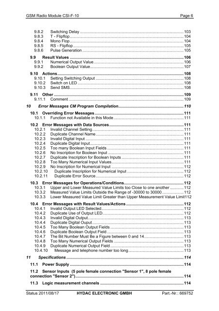
GSM Radio Module <strong>CSI</strong>-F-<strong>10</strong> Page 69.8.2 Switching Delay ............................................................................................<strong>10</strong>39.8.3 T - Flipflop.....................................................................................................<strong>10</strong>49.8.4 Mono Flop.....................................................................................................<strong>10</strong>49.8.5 RS - Flipflop ..................................................................................................<strong>10</strong>59.8.6 Pulse Generation ..........................................................................................<strong>10</strong>59.9 Result Values .....................................................................................................<strong>10</strong>69.9.1 Numerical Output Value................................................................................<strong>10</strong>69.9.2 Boolean Output Value...................................................................................<strong>10</strong>79.<strong>10</strong> Actions................................................................................................................<strong>10</strong>89.<strong>10</strong>.1 Setting Switching Output ..............................................................................<strong>10</strong>89.<strong>10</strong>.2 Switch on LED ..............................................................................................<strong>10</strong>89.<strong>10</strong>.3 Send SMS.....................................................................................................<strong>10</strong>89.11 Other ...................................................................................................................<strong>10</strong>99.11.1 Comment ......................................................................................................<strong>10</strong>9<strong>10</strong> Error Messages CM Program Compilation..........................................................1<strong>10</strong><strong>10</strong>.1 Overriding Error Messages...............................................................................111<strong>10</strong>.1.1 Function not Available in this Mode ..............................................................111<strong>10</strong>.2 Error Messages with Data Sources..................................................................111<strong>10</strong>.2.1 Invalid Channel Setting.................................................................................111<strong>10</strong>.2.2 Duplicate Channel Name..............................................................................111<strong>10</strong>.2.3 Invalid Digital Input .......................................................................................111<strong>10</strong>.2.4 Duplicate Digital Input...................................................................................111<strong>10</strong>.2.5 Too many Boolean Input Fields ....................................................................111<strong>10</strong>.2.6 No Inscription for Boolean Input ...................................................................111<strong>10</strong>.2.7 Duplicate Inscription for Boolean Inputs .......................................................111<strong>10</strong>.2.8 Too Many Numerical Input Values................................................................111<strong>10</strong>.2.9 No Inscription for Numerical Input ................................................................112<strong>10</strong>.2.<strong>10</strong> Duplicate Inscription for Numerical Input ..................................................112<strong>10</strong>.2.11 Duplicate Error Source..............................................................................112<strong>10</strong>.3 Error Messages for Operations/Conditions.....................................................112<strong>10</strong>.3.1 Upper and Lower Measured Value Limits too Close to one another ............112<strong>10</strong>.3.2 Measured Value Limits Outside the Range of -30000 to 30000 ...................112<strong>10</strong>.3.3 Lower Measured Value Limit Greater than Upper Measurement Value Limit112<strong>10</strong>.4 Error Messages with Result Values/Actions ...................................................112<strong>10</strong>.4.1 Invalid Output LED Selected.........................................................................112<strong>10</strong>.4.2 Duplicate Use of Output LED........................................................................112<strong>10</strong>.4.3 Invalid Digital Output.....................................................................................113<strong>10</strong>.4.4 Duplicate Digital Ouput .................................................................................113<strong>10</strong>.4.5 Too Many Boolean Output Fields .................................................................113<strong>10</strong>.4.6 Duplicate Boolean Output Field ....................................................................113<strong>10</strong>.4.7 The Bit Number Must Be a Figure between 0 and 14...................................113<strong>10</strong>.4.8 Too Many Numerical Output Fields ..............................................................113<strong>10</strong>.4.9 Duplicate Numerical Output Field .................................................................113<strong>10</strong>.4.<strong>10</strong> Message and telephone number too long.................................................11311 Specifications ........................................................................................................11411.1 Power Supply .....................................................................................................11411.2 Sensor Inputs (5 pole female connection "Sensor 1", 8 pole femaleconnection "Sensor 2")................................................................................................11411.3 Logic measurement channels ..........................................................................114Status 2011/08/17 HYDAC ELECTRONIC GMBH Part.-Nr.: 669752


