Synchronous Motors
Synchronous Motors
Synchronous Motors
- No tags were found...

You also want an ePaper? Increase the reach of your titles
YUMPU automatically turns print PDFs into web optimized ePapers that Google loves.
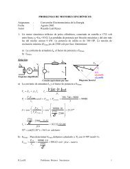
TORQUETorque makes the wheelsgo ’roundTorque may represent either the turning effortdeveloped by a motor or the resistance to turningeffort exerted by the driven load. It is defined astangential pull at a radius of one unit from thecenter of rotation. In the United States it ismeasured in foot-pounds or inch-pounds. For agiven condition:Torque =HP X 5250rpmTorque = Tangential effort in pounds at onefoot radiusHP = Horsepower developedrpm = Revolutions per minuteIn some cases motor torques are expressed infoot-pounds; however, they are usually expressedas a percentage of full load torque.A synchronous motor has many importanttorques that determine the ability of the motor tostart, accelerate, pull its connected load into step,and operate it through anticipated peak loadswithin its design limits.These torques may be described as:1. Starting torque or breakaway torque.This is the torque developed at the instant ofstarting at zero speed.2. Accelerating torque.This is the motor torque developed from standstillto pull-in speed minus the load torque.Starting and accelerating torquesThe characteristics of these torques are closelyallied and will be discussed together. Fiveindividual torques contribute to the turning effort ofa synchronous motor during starting andaccelerating. They are produced by:1. Amortisseur windings2. Field windings3. Hysteresis in pole faces4. Eddy currents in pole faces5. Variation in magnetic reluctanceOf the five torques, only the first two aresignificant during starting and accelerating, andonly their characteristics will be discussed here.The amortisseur windingsThese windings develop most of the startingand accelerating torque in motors of this type. Thiswinding consists of a partially distributed cagewinding, with bars imbedded in the pole faces andshort circuited at each end by end rings. Varyingthe number, location and resistance of these barswill have a substantial effect on the torque and onthe kVA input. In some cases a double cage,consisting of one row of shallow bars and one rowof deepset bars, is used. These may be separate, orthey may have common end rings as circumstanceswill dictate. Typical amortisseur windings areillustrated in Figure 15.3. Pull-up torque.This is the minimum torque developedbetween stand-still and the pull-in.50043kVA CURVES104. Pull-in torque.This is the torque developed during thetransition from slip speed to synchronousspeed and generally is defined at 95% speed.5. <strong>Synchronous</strong> torque.This is the steady state torque developedduring operation. It is load dependent.6. Pull-out torque.This is defined as the maximum steady statetorque developed by the motor, for oneminute, before it pulls out of step due tooverload.% OF FULL-LOAD TORQUE AND kVA400300200214100321TORQUE CURVES00 25 50 75 100% SYNCHRONOUS RPM