Synchronous Motors
Synchronous Motors
Synchronous Motors
- No tags were found...

Create successful ePaper yourself
Turn your PDF publications into a flip-book with our unique Google optimized e-Paper software.
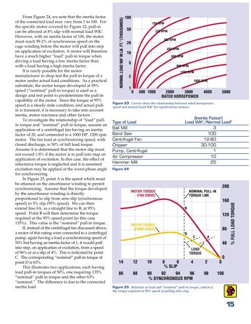
From Figure 24, we note that the inertia factorof the connected load may vary from 1 to 100. Forthe specific motor covered by Figure 22, pull-incan be affected at 8% slip with normal load WK 2 .However, with an inertia factor of 100, the motormust reach 99.2% of synchronous speed on thecage winding before the motor will pull into stepon application of excitation. A motor will thereforehave a much higher “load” pull-in torque whendriving a load having a low inertia factor thanwith a load having a high inertia factor.It is rarely possible for the motormanufacturer to shop test the pull-in torque of amotor under actual load conditions. As a practicalsubstitute, the motor torque developed at 95%speed (“nominal” pull-in torque) is used as adesign and test point to predetermine the pull-incapability of the motor. Since the torque at 95%speed is a steady state condition, and actual pullinis transient, it is necessary to take into accountinertia, motor reactance and other factors.To investigate the relationship of “load” pullintorque and “nominal” pull-in torque, assume anapplication of a centrifugal fan having an inertiafactor of 20, and connected to a 1000 HP, 1200 rpmmotor. The fan load at synchronizing speed, withclosed discharge, is 50% of full load torque.Assume it is determined that the motor slip mustnot exceed 1.8% if the motor is to pull into step onapplication of excitation. In this case, the effect ofreluctance torque is neglected and it is assumedexcitation may be applied at the worst phase anglefor synchronizing.In Figure 25, point A is the speed which mustbe attained on the amortisseur winding to permitsynchronizing. Assume that the torque developedby the amortisseur winding is directlyproportional to slip from zero slip (synchronousspeed) to 5% slip (95% speed). We can thenextend line 0A, as a straight line to B, at 95%speed. Point B will then determine the torquerequired at the 95% speed point (in this case135%). This value is the “nominal” pull-in torque.If, instead of the centrifugal fan discussed above,a motor of this rating were connected to a centrifugalpump, again having a load a synchronizing speed of50% but having an inertia factor of 1, it would pullinto step, on application of excitation, from a speedof 96% or at a slip of 4%. This is indicated by pointC. The corresponding “nominal” pull-in torque atpoint D is 63%.This illustrates two applications, each havingload pull-in torques of 50%, one requiring 135%“nominal” pull-in torque and the other 63%“nominal.” The difference is due to the connectedinertia load.NORMAL LOAD Wk 2 IN LB. FT. 2 (THOUSANDS)1410050201052150 RPM225 RPM300 RPM450 RPM600 RPM900 RPM1200 RPM1800 RPM10 500 1000 2000 3000 4000 5000RATED HORSEPOWERFigure 23 Curves show the relationship between rated horsepower,speed and normal load WK 2 for synchronous motors.(Inertia Factor)Type of Load Load WK 2 /Normal Load 2Ball Mill 3Band Saw 100Centrifugal Fan 12-60Chipper 30-100Pump, Centrifugal 1Air Compressor 10Hammer Mill 25Figure 2486MOTOR TORQUE(FAN DRIVE)MOTOR TORQUE(PUMP DRIVE)012 10 8 6 4 2 0% SLIP88 90 92 94 96 98 100% SYNCHRONOUS RPMBDNOMINAL PULL-INTORQUE LINECLOADTORQUEFigure 25 Relation of load and “nominal” pull-in torque, which isthe torque required at 95% speed of pulling into step.A2001601208040% FULL LOAD TORQUE15