Synchronous Motors
Synchronous Motors
Synchronous Motors
- No tags were found...

Create successful ePaper yourself
Turn your PDF publications into a flip-book with our unique Google optimized e-Paper software.
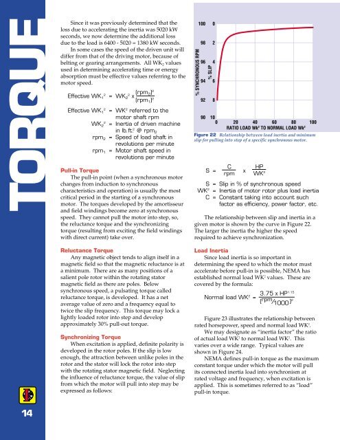
TORQUESince it was previously determined that theloss due to accelerating the inertia was 5020 kWseconds, we now determine the additional lossdue to the load is 6400 - 5020 = 1380 kW seconds.In some cases the speed of the driven unit willdiffer from that of the driving motor, because ofbelting or gearing arrangements. All WK 2 valuesused in determining accelerating time or energyabsorption must be effective values referring to themotor speed.Effective WK 12 = WK 22 x (rpm 2) 2(rpm 1 ) 2Effective WK 12 = WK 2 referred to themotor shaft rpmWK 22 = Inertia of driven machinein lb.ft. 2 @ rpm 2rpm 2 = Speed of load shaft inrevolutions per minuterpm 1 = Motor shaft speed inrevolutions per minutePull-in TorqueThe pull-in point (when a synchronous motorchanges from induction to synchronouscharacteristics and operation) is usually the mostcritical period in the starting of a synchronousmotor. The torques developed by the amortisseurand field windings become zero at synchronousspeed. They cannot pull the motor into step, so,the reluctance torque and the synchronizingtorque (resulting from exciting the field windingswith direct current) take over.Reluctance TorqueAny magnetic object tends to align itself in amagnetic field so that the magnetic reluctance is ata minimum. There are as many positions of asalient pole rotor within the rotating statormagnetic field as there are poles. Belowsynchronous speed, a pulsating torque calledreluctance torque, is developed. It has a netaverage value of zero and a frequency equal totwice the slip frequency. This torque may lock alightly loaded rotor into step and developapproximately 30% pull-out torque.Synchronizing TorqueWhen excitation is applied, definite polarity isdeveloped in the rotor poles. If the slip is lowenough, the attraction between unlike poles in therotor and the stator will lock the rotor into stepwith the rotating stator magnetic field. Neglectingthe influence of reluctance torque, the value of slipfrom which the motor will pull into step may beexpressed as follows:% SYNCHRONOUS RPM1009896949290% SLIP02468100 20 40 60 80 100RATIO LOAD Wk 2 TO NORMAL LOAD Wk 2Figure 22 Relationship between load inertia and minimumslip for pulling into step of a specific synchronous motor.S =C HPrpmxWK 2S = Slip in % of synchronous speedWK 2 = Inertia of motor rotor plus load inertiaC = Constant taking into account suchfactor as efficiency, power factor, etc.The relationship between slip and inertia in agiven motor is shown by the curve in Figure 22.The larger the inertia the higher the speedrequired to achieve synchronization.Load InertiaSince load inertia is so important indetermining the speed to which the motor mustaccelerate before pull-in is possible, NEMA hasestablished normal load WK 2 values. These arecovered by the formula:Normal load WK 2 =3.75 x HP1.15( rpm / 1000 ) 2Figure 23 illustrates the relationship betweenrated horsepower, speed and normal load WK 2 .We may designate as “inertia factor” the ratioof actual load WK 2 to normal load WK 2 . Thisvaries over a wide range. Typical values areshown in Figure 24.NEMA defines pull-in torque as the maximumconstant torque under which the motor will pullits connected inertia load into synchronism atrated voltage and frequency, when excitation isapplied. This is sometimes referred to as “load”pull-in torque.14