Synchronous Motors
Synchronous Motors
Synchronous Motors
- No tags were found...

You also want an ePaper? Increase the reach of your titles
YUMPU automatically turns print PDFs into web optimized ePapers that Google loves.
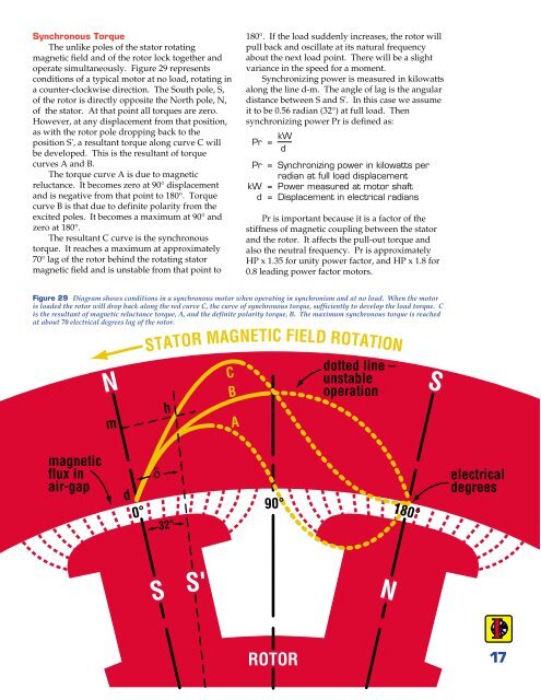
<strong>Synchronous</strong> TorqueThe unlike poles of the stator rotatingmagnetic field and of the rotor lock together andoperate simultaneously. Figure 29 representsconditions of a typical motor at no load, rotating ina counter-clockwise direction. The South pole, S,of the rotor is directly opposite the North pole, N,of the stator. At that point all torques are zero.However, at any displacement from that position,as with the rotor pole dropping back to theposition S', a resultant torque along curve C willbe developed. This is the resultant of torquecurves A and B.The torque curve A is due to magneticreluctance. It becomes zero at 90° displacementand is negative from that point to 180°. Torquecurve B is that due to definite polarity from theexcited poles. It becomes a maximum at 90° andzero at 180°.The resultant C curve is the synchronoustorque. It reaches a maximum at approximately70° lag of the rotor behind the rotating statormagnetic field and is unstable from that point to180°. If the load suddenly increases, the rotor willpull back and oscillate at its natural frequencyabout the next load point. There will be a slightvariance in the speed for a moment.Synchronizing power is measured in kilowattsalong the line d-m. The angle of lag is the angulardistance between S and S'. In this case we assumeit to be 0.56 radian (32°) at full load. Thensynchronizing power Pr is defined as:Pr = kW dPr = Synchronizing power in kilowatts perradian at full load displacementkW = Power measured at motor shaftd = Displacement in electrical radiansPr is important because it is a factor of thestiffness of magnetic coupling between the statorand the rotor. It affects the pull-out torque andalso the neutral frequency. Pr is approximatelyHP x 1.35 for unity power factor, and HP x 1.8 for0.8 leading power factor motors.Figure 29 Diagram shows conditions in a synchronous motor when operating in synchronism and at no load. When the motoris loaded the rotor will drop back along the red curve C, the curve of synchronous torque, sufficiently to develop the load torque. Cis the resultant of magnetic reluctance torque, A, and the definite polarity torque, B. The maximum synchronous torque is reachedat about 70 electrical degrees lag of the rotor.NmSTATOR MAGNETIC FIELD ROTATIONhCBAdotted line –unstableoperationSmagneticflux inair-gapd0°δ32°90°180°electricaldegreesSS'NROTOR17