Synchronous Motors
Synchronous Motors
Synchronous Motors
- No tags were found...

Create successful ePaper yourself
Turn your PDF publications into a flip-book with our unique Google optimized e-Paper software.
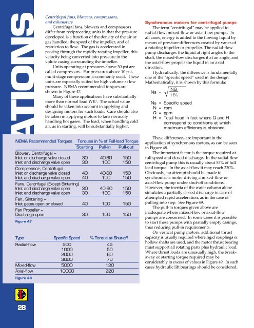
APPLICATIONSCentrifugal fans, blowers, compressors,and exhaustersCentrifugal fans, blowers and compressorsdiffer from reciprocating units in that the pressuredeveloped is a function of the density of the air orgas handled, the speed of the impeller, and ofrestriction to flow. The gas is accelerated inpassing through the rapidly rotating impeller, thisvelocity being converted into pressure in thevolute casing surrounding the impeller.Units operating at pressures above 30 psi arecalled compressors. For pressures above 10 psi,multi-stage compression is commonly used. Theseunits are especially suited for high volume at lowpressure. NEMA recommended torques areshown in Figure 47.Many of these applications have substantiallymore than normal load WK 2 . The actual valueshould be taken into account in applying anddesigning motors for such loads. Care should alsobe taken in applying motors to fans normallyhandling hot gases. The load, when handling coldair, as in starting, will be substantially higher.NEMA Recommended Torques Torques in % of Full-load TorqueStarting Pull-in Pull-outBlower, Centrifugal –Inlet or discharge valve closed 30 40-60 150Inlet and discharge valve open 30 100 150Compressor, CentrifugalInlet or discharge valve closed 40 40-60 150Inlet and discharge valve open 40 100 150Fans, Centrifugal (Except Sintering)Inlet and discharge valve open 30 40-60 150Inlet and discharge valve open 30 100 150Fan, Sintering –Inlet gates open or closed 40 100 150Fan Propeller –Discharge open 30 100 150Figure 47Type Specific Speed % Torque at Shut-offRadial-flow 500 451000 502000 603000 70Mixed-flow 5000 120Axial-flow 10000 220Figure 48<strong>Synchronous</strong> motors for centrifugal pumpsThe term “centrifugal” may be applied toradial-flow, mixed-flow or axial-flow pumps. Inall cases, energy is added to the flowing liquid bymeans of pressure differences created by vanes ofa rotating impeller or propeller. The radial-flowpump discharges the liquid at right angles to theshaft, the mixed-flow discharges it at an angle, andthe axial-flow propels the liquid in an axialdirection.Hydraulically, the difference is fundamentallyone of the “specific speed” used in the design.Mathematically, it is shown by this formula:NQNs = H 3 ⁄4Ns = Specific speedN = rpmQ = gpmH = Total head in feet where Q and Hcorrespond to conditions at whichmaximum efficiency is obtainedThese differences are important in theapplication of synchronous motors, as can be seenin Figure 48.The important factor is the torque required atfull speed and closed discharge. In the radial-flowcentrifugal pump this is usually about 55% of fullload torque. In the axial-flow it may reach 220%.Obviously, no attempt should be made tosynchronize a motor driving a mixed-flow oraxial-flow pump under shut-off conditions.However, the inertia of the water column alonesimulates a partially closed discharge in case ofattempted rapid acceleration, as in the case ofpulling into step. See Figure 49.The pull-in torques given above areinadequate where mixed-flow or axial-flowpumps are concerned. In some cases it is possibleto start these pumps with partially empty casings,thus reducing pull-in requirements.On vertical pump motors, additional thrustcapacity is usually required where rigid couplings orhollow shafts are used, and the motor thrust bearingmust support all rotating parts plus hydraulic load.Where thrust loads are unusually high, the breakawayor starting torque required may beconsiderably in excess of values in Figure 49. In suchcases hydraulic lift bearings should be considered.28