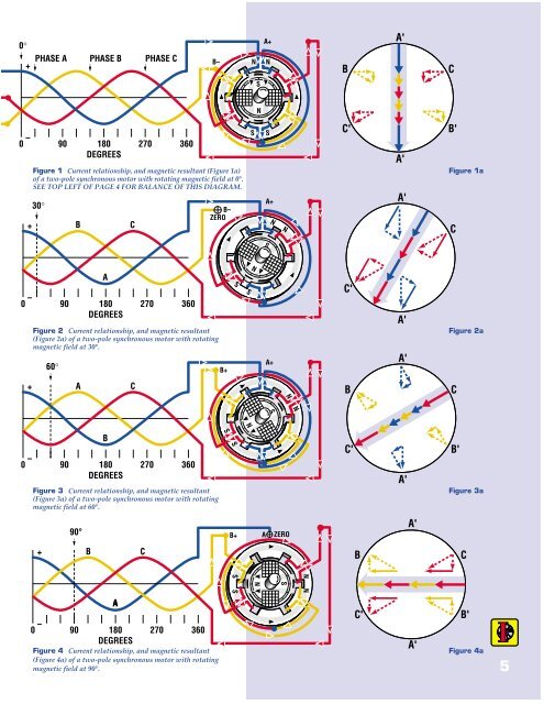
GEARED<strong>Synchronous</strong> motors are“geared” to the power supplyDuring operation, the stator of a polyphasealternating current motor has a rotating magneticfield. This is developed by the direction andamount of current flow in the stator coils.Figure 1 represents a two-pole, three-phasestator, having one slot per pole per phase in whichthere are six stator coils. These coils are connectedto a three phase power supply having phaserotation A, B, C.At the instant shown, the current in phase A inmaximum positive enters the motor at A+ andleaves at neutral where the three conductors meet.The “A” arrows in Figure 1 represent the magneticflux (lines of force) developed by this current. Atthis instant the current in phases B and C is negative,each equal to one-half the current in A. Themagnetic flux developed by B is shown by the “B”arrows, each equal to half the “A” arrows. The fluxdeveloped by C is represented by the “C” arrow,each equal to half of A. B and C also have horizontalcomponents but, as shown, they cancel out.The result is a vertically polarized stator, witha North pole at the top and a South pole at thebottom. The arrows show the flux flowingdownward through the rotor.One-twelfth revolution later (Figure 2), thepositive current in A has dropped in value and isequal to the negative value in C, which hasincreased in value. The current in B is zero. Equalfield strengths are developed by A and C and,canceling out the opposing components, we findthe total flux in Figure 2a to be represented by thetwo “A” and two “C” arrows, 30° from the formerposition.At the 60° position, shown in Figure 3, thecurrent in phase B and the corresponding statorcoils are positive and equal to phase A. Thecurrent in phase C is maximum negative. Aftercanceling out the opposing components, we find aresultant field, as shown in Figure 3a composedprincipally of current in phase C, supplementedby smaller equal amounts in phases A and B.BAFigure 1 See top left of page 5 for balance ofthis diagram, plus its caption.Figures 4 and 4a complete a one-quarter turnor 90° of a two-pole motor. Continuation of thiscompletes one revolution.The rotor shown in the above figures is that ofa two-pole synchronous motor having definiteNorth and South poles developed by directcurrent flowing in the field winding. The currentflows from the observer in the left hand portion ofthe winding, towards the observer in the righthand portion. Using the “right-hand rule” thisdevelops a North pole at the bottom of the rotorand a South pole at the top.The magnetic poles developed in the stator areexactly opposite. However, unlike poles attract,so the North pole of the rotor lines up under theSouth pole of the stator.As the North pole of the stator shifts 30°clockwise, the rotor is pulled along with it, and(assuming no load on the rotor shaft and nolosses) the rotor and stator poles line up exactly asshown. Each rotor pole lags behind itscorresponding stator pole by 20 to 30 electricaldegrees at full load. This is called the “loadangle,” and it is a function of motor load, whereincreased torque requirements result in greatermagnetic pull and a greater displacement frommagnetic center.A normal two pole stator differs in manyrespects from that shown in Figures 1 through 4.Instead of one slot per phase there are six or seven.The coil pitch is about 120° instead of 60° and willoverlap the coils of the various phases. Theconfiguration shown results in rotation by a seriesof jerks. The use of more closely spaced coils willresult in a smoother, more uniform turning action.CFigures 1 through 4 AC Generator.Three-phase power supply for <strong>Synchronous</strong> Motor. Generatorvoltage is assumed equal and in phase with the current; thereis no load torque for friction so rotor and stator poles are freeto line up magnetically.4
0°0 – +0 – +PHASE A PHASE B PHASE C90 180DEGREES270 360Figure 1 Current relationship, and magnetic resultant (Figure 1a)of a two-pole synchronous motor with rotating magnetic field at 0°.SEE TOP LEFT OF PAGE 4 FOR BALANCE OF THIS DIAGRAM.30°BA90 180DEGREESC270 360Figure 2 Current relationship, and magnetic resultant(Figure 2a) of a two-pole synchronous motor with rotatingmagnetic field at 30°.60°B–B–ZEROB+S SNSNSNA+SNSA+NA+NBC'C'A'A'A'A'A'CB'Figure 1aCFigure 2a0 – +AB90 180DEGREESC270 360Figure 3 Current relationship, and magnetic resultant(Figure 3a) of a two-pole synchronous motor with rotatingmagnetic field at 60°.S SNSNNBC'A'CB'Figure 3a90° AB+ZEROA'0 – +BA90 180DEGREESC270 360Figure 4 Current relationship, and magnetic resultant(Figure 4a) of a two-pole synchronous motor with rotatingmagnetic field at 90°.S SNSNNBC'A'CB'Figure 4a5