Synchronous Motors
Synchronous Motors
Synchronous Motors
- No tags were found...

Create successful ePaper yourself
Turn your PDF publications into a flip-book with our unique Google optimized e-Paper software.
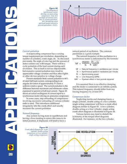
APPLICATIONSFigure 42Oscillogram ofsynchronous motordriving a reciprocatingcompressor. Line A isenvelope of current wave,B-C is current pulsation.B-C divided by ratedfull-load motor current ispercent pulsation = 55.2%.Current pulsationA reciprocating compressor has a varyingtorque requirement per revolution, depending onnumber of cylinders, crank angle, etc. As discussedpreviously, the angle of rotor lag and the amount ofstator current vary with torque. There will be acyclic pulsation of the load current during eachrevolution. This in itself is not too objectionable,but excessive current pulsation may result inappreciable voltage variation and thus affect lightsor other devices sensitive to voltage change.Present standards limit current pulsation to 66%of rated full-load current, corresponding to anangular deviation of approximately 5% from auniform rotative speed. The current pulsation is thedifference between maximum and minimum valuesexpressed in percent of full-load current. Figure 42shows an actual oscillogram of current input to asynchronous motor driving an ammonia compressor.In some cases, step unloading of compressorsinvolving successive unloading of various cylinderends is used. This introduces additionalirregularity into the crank effort and usuallyincreases the current pulsation.Natural frequencyAny system having mass in equilibrium andhaving a force tending to return this mass to itsinitial position, if displaced, will tend to have aFigure 43Crank effort diagram for a onecylinder, double-actingcompressor, or two cylinder,single-acting compressor.TORQUEIN FOOT POUNDSABCnatural period of oscillation. The commonpendulum is a good example.The natural frequency of this oscillation in asynchronous motor is determined by the formula:NF = 35200 Pr x HzN WK 2NF = Natural frequency in oscillations per minuteN = <strong>Synchronous</strong> speed in revolutions per minutePr = Synchronizing powerHz = Line frequency (CPS)WK 2 = Flywheel effect in foot pounds squaredIt is assumed there is no effective dampingand the motor is connected to an infinite system.This natural frequency should differ from anyforcing frequency by at least 20%Compressor factorNeglecting inertia and damping forces, asingle cylinder, double acting or a two cylinder,single acting compressor will have a crank effortdiagram similar to Figure 43. A two cylinder,double acting or a four cylinder, single actingcrank effort diagram is illustrated in Figure 44.Various factors may tend to disturb thesymmetry of the torque effort diagramsillustrated. For instance, on the two cylinder,ONE REVOLUTION260 180 360DEGREES