Synchronous Motors
Synchronous Motors
Synchronous Motors
- No tags were found...

You also want an ePaper? Increase the reach of your titles
YUMPU automatically turns print PDFs into web optimized ePapers that Google loves.
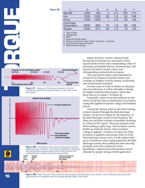
TORQUEFREQUENCY OF FIELD-DISCHARGE CURRENT60 CYCLES30 CYCLES 6 CYCLES0% 50% 90%CORRESPONDING MOTOR SPEEDFigure 26Figure 27 Frequency of the current induced in the fieldwinding of a synchronous motor declines as the motor comesup to speed.Figure 28a Oscillogram shows synchronizing of the motor byapplication of dc excitation. If the point of application anticipatesthe interval before synchronizing as shown, the excitation willreadily build up to pull the rotor into step smoothly.InducedfieldcurrentINDUCED FIELD CURRENTExcitationappliedhereTIME (seconds)1 2 3 4 5 6 7Ball Mill 1000 180 4 4.3 100 115Fan 1000 1200 20 1.8 50 138Pump 1000 1200 1 4.0 50 63CentrifugalCompressor 2500 900 15 1.8 50 138Chipper 1500 277 50 1.0 10 501. Type of load2. Horsepower3. RPM4. Assumed inertia factor5. Maximum slip from which motor will pull-in, in percent6. Load torque required at pull-in7. Nominal pull-in torqueMOTOR SYNCHRONIZED3 CYCLESX95% FIELD EXCITATIONAPPLIEDExcitation applied hereRotor pulls promptlyinto synchronismwithout pole slippageRotor pulls promptly intosynchronism withoutpole slippageFigure 26 shows various common loadshaving typical horsepower and speed values,typical inertia factors and corresponding values ofmaximum permissible slip for synchronizing, withtypical load pull-in torque values, andcorresponding nominal pull-in torques.The load pull-in torque value (indicated incolumn 6) for chippers is merely friction andwindage as chippers must be started, accelerated,and synchronized unloaded.In some cases, in order to obtain an adequaterate of acceleration, it will be desirable to designfor higher nominal pull-in torque values thanthose shown in column 7 of Figure 26.Frequently, where it has been difficult for themotor to pull into step on application of excitation,raising the applied excitation voltage will facilitatepull-in.During the starting interval, the field windingis short-circuited through the field dischargeresistor. As shown in Figure 27, the frequency ofthe field discharge current is line frequency (60Hertz on a 60 Hertz system) at standstill, decliningto 3 Hertz at 95% speed. The time constant of thefield winding is quite long. The excitation currentbuilds up relatively slowly when excitationvoltage is applied. As shown in Figure 28, if theexcitation is applied at the proper interval of thefield discharge current wave, it will readily buildup to a maximum value, being assisted by the fielddischarge current, thus pulling the rotor into steppromptly and with a minimum of linedisturbance. Improved synchronization can beobtained by proper timing of field application.162.02.5Figure 28b Stator Current. Rotor pulls into synchronism with minimum stator current. (Note: Pulsations of current aftersynchronism are oscillations due to very large flywheel effect of the load.)