Sequential Circuits Prophet-5 Service Manual - Audiofanzine
Sequential Circuits Prophet-5 Service Manual - Audiofanzine
Sequential Circuits Prophet-5 Service Manual - Audiofanzine

You also want an ePaper? Increase the reach of your titles
YUMPU automatically turns print PDFs into web optimized ePapers that Google loves.
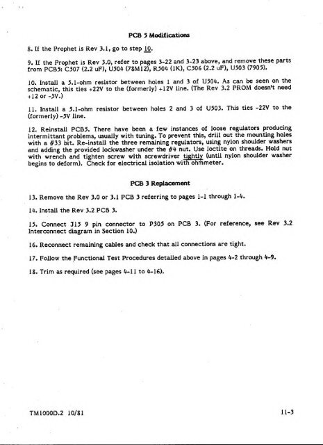
TJPCB 5 Modifications8. If the <strong>Prophet</strong> is Rev 3.1, go to step ^0.9. If the <strong>Prophet</strong> is Rev 3.0, refer to pages 3-22 and 3-23 above, and remove these partsfrom PCB5: C507 (2.2 uF), U50^ (78MI2), R50* (IK), C506 (2.2 uF), U503 (7905).10. Install a 5.1-ohm resistor between holes 1 and 3 of U50^. As can be seen on theschematic, this ties +22V to the (formerly) +12V line.+ 12or-5V.)(The Rev 3.2 PROM doesn't need11. Install a 5.1-ohm resistor between holes 2 and 3 of U503. This ties -22V to the(formerly) -5V line.12. Reinstall PCB5. There have been a few instances of loose regulators producinginter mittant problems, usually with tuning. To prevent this, drill out the mounting holeswith a #33 bit. Re-install the three remaining regulators, using nylon shoulder washersand adding the provided lockwasher under the //4 nut. Use loctite on threads. Hold nutwith wrench and tighten screw with screwdriver tightly (until nylon shoulder washerbegins to deform). Check for electrical isolation with ohmmeter.PCB 3 Replacement13. Remove the Rev 3.0 or 3.1 PCB 3 referring to pages 1-1 through 1-4.14. Install the Rev 3.2 PCB 3.15. Connect 315 9 pin connector to P305 on PCB 3. (For reference, see Rev 3.2Interconnect diagram in Section 10.)16. Reconnect remaining cables and check that all connections are tight.17. Follow the Functional Test Procedures detailed above in pages 4-2 through 4-9.18. Trim as required (see pages ^^-U to It-16).TM1000D.2 10/81 11-3