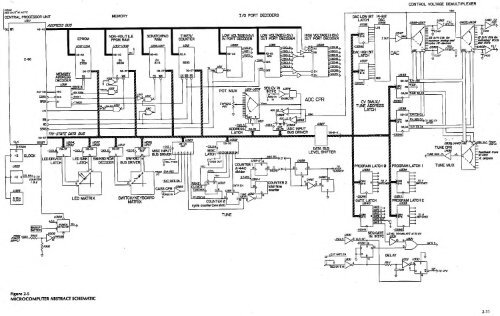
FROM^CENTRAL PROCESSOR UNITU3//ADDRESS BUSINTA^-ASMEMORY7I/O PORT DECODERSUDW VOLTAGEB-SV)OUT PORT DKODERHIGH VOLTAGE (+I5V)OUT PORT DECODERU529^SOHB.DACLOWBITLATCH^OJf14-BITLSBDAC«3«lOUTCONTROL VOLTAGE DEMULTIPLEXER0355-0557^Atec^^ FILTTatkcv^£3S/MCVi for=.common anafog and= W'Vits. SEO0405,0406Ej""-^s/Hcysifyr-kxff¥k/uai VCOsnuTZ-80Aio-fttaMEMORYADDRESSDECODERU5mRQMg-a3x2708,-NV RAM-pwnOH.Ae-A96x6508 6253T?—00-07 BIBBCS WR fiP 1a-mmsi5^^-lORQ,-WR,A3-A&ABCdG2A8ZBcCSOLI^CSOLS^fjCSOHl>jC50H3vjCS0H4vjCSOHfis,IDAC HIGH errLATCH-CS0H7tf3srMseDACaj55DBHQa-Q203S/H ABCTUNEIffl,I2^n>^*^oj.^.^T IS"?J^,-RAM I.-TIMERPOT MUXU20t-(/203^T^"^ ^^t ADC CPRADC HI ll^*^CV DMUX/TUNE ADDRESSLATCH-CS0H36^739CLKU325> -^Z03265 MhzCLOCK2,5 MHzCLOCK2^ MMzlORQ >00-07RESETLED DRIVERLATCHLED SINKLATCHBLED MATRIXSWKBDRCWDECODERSW/KBO^BUS DRIVER15'ASWITCH/KEYBOARDMATRIXMISC INPUTr BUS DRIVER 14 3 5 28Pff^ ENAfiECCASS CPRFFDFAKECLOCKTUNE MUXFF STATUS-Ca-Q4MISCLATCHQcASS OUT-FFCL'FFPẠCL P U3326COUNTERcycle counter (one shot)umsXwCOUNTER IA-440 '5dividerCNTREN2.5 MHi ^TUNECMTfiUZ15-2>16440 SEL1065ADCLO^?.dS^Ss»27Iadc inputbus driveri/'fl!®3 Jl440 >24aeJt from^vcoVf, outputsi/JO^TUNEDBH „0-5 QGgIE4 . .TO e^smrcHESVri"^GATES-csca-5iOJ/-CS0H5^jgCLRIWTSEQ GATEIN INTFC-csot^LEVBL TRANSLATE i5 TOSVU35IGAT^S >-EXT GATE ENDELAYu^ooSEO GATE INCJ/5TrocpuFigure 2-5MICROCOMPUTER ABSTRACT SCHEMATIC2-11
.'2-10 MICROPROCESSOR, MEMORY, AND I/O INTERFACEPlease see Figure 2-5 and schematic SD331. The Power Detector (PWR DET) circuit controls CPU start-upand shut-off through the Clock and -RESET signals. PWR DET also contains battery BT301 which providesback-up power, Vnv, for Non-Volatile (NV) RAM. The NV RAM's low current requirement allows thebattery a ten-year life expectancy.WARNING! BT301 MAY EXPLODE IFSHORTED FOR ANY LENGTH OF TIME, ALTHOUGH IT WILLUSUALLY "JUST" VENT NOXIOUS GASES.Vnv also powers U309, CMOS quad NOR gate. With power off, inverter-connected U309-10 is high. Thishigh and that through D301 make U309-13 low holding the CPU -RESET. -RESET initializes the CPU andresets its program counter (PC) to execute the instruction in location 0000 once the Clock starts and-RESET goes high.When power is switched on the CPU CLOCK starts immediately because the lower power supplyvoltages stabilize before the higher voltages. When power is switched off, the higher supply voltagesdecay more quickly. If the CPU is being clocked while power rises or falls, the EPROMs couldconceivably cause spurious data to be written Into NV RAM, since they operate on a higher voltage thanthe CPU (+12V as opposed to +5V). Accordingly, PWR DET immediately resets the CPU when powerdrops, and disables the NV RAM -CS (see below). Divider R303/R302 monitors the highest power supplyvoltage, which must achieve full value for U309-10to go low. This discharges C303 through R3-1 so afterabout one second U309-3 goes high, starting the CPU. With the power on, D303 provides 5V for Vnv.The Data, Address and Control Buses were basically described in the preceding paragraph. A0-A9 set upone out of 1024 addresses on all the memory chips, while the specific 1-K block CS is decoded fromA10-A12, -MREQ, and -RFSH. -MREQ actually signifies the Address Bus Indeed holds a valid address fora memory read or write operation. Intended for use with dynamic RAMs, -RFSH indicates the AddressBus instead holds a refresh address. Therefore to enable any memory, -MREQ must be low and-RFSH high.A15, the most significant Address Bus line is gated with the ENABLE RECORD (ENA REC) signal throughU320-11. ENA REC is pulled high by R308 unless grounded by the back-panel RECORDENABLE/DISABLE switch which, of course, prevents unintended recording into NV RAM. Gating A15 inthis way means that although NV RAM Is read from memory addresses OCOO-OFFF(H), it is written intothrough addresses 8C00-8CFFF(H)—rather than just relying on the usual -RD and -WR signals.-WR indicates the Data Bus holds valid data to be stored in the addressed memory or I/O device. -RDindicates the CPU wants to read data from memory or an I/O device. -lORQ indicates A0-A7 hold avalid address for an I/O operation. The -INT input is discussed in paragraph 2-15.J'The <strong>Prophet</strong>'s program is contained In three 2708 1024 x 8-blt ultra-violet erasable programmableread-only memories (EPROM) occupying addresses 000-03FF (ROMO), 0400-07FF (ROM1) and0800-OBFF (ROM2). Since no write operations are performed into ROM, the appropriate CS is sufficientto place an instruction on the bus.THE NV RAM which holds the patch programs is made from eight 6508 1024x i-bit CMOS static RAMs.Total current demand on the backup battery is 10 uA, or less. Many steps have been taken to protect NV,although cassette storage makes a catastrophic NV RAM failure unnecessary.TECHNICIANS SHOULD BACK-UP PROGRAMS THROUGH THE CASSETTESERVICING, (IT TAKES ONLY TWO MINUTES.) PLAYERS SHOULD BE ENCOURAGED TO BACK-UPINTERFACE BEFORETHEIR PROGRAMS ON CASSETTES AND/OR ON BLANK PANEL DIAGRAMS (INCLUDED INOPERATION MANUAL), SINCE IT IS ALWAYS POSSIBLE FOR PROGRAMS TO BE LOST THROUGH THECOURSE OF SERVICE.2-12
- Page 1 and 2: ^^. ^ ^s .y ^,-j?^ ^^w^-^>&i^^^V^?v
- Page 3 and 4: PROPHET-5 SYNTHESIZERTECHNICAL MANU
- Page 5 and 6: iJTable of ContentsISECTION 1MECHAN
- Page 7 and 8: '1SECTION 1MECHANICAL1-0 GENERALThi
- Page 9 and 10: Raise the top panel assembly to ser
- Page 11 and 12: 1-5 PCB 1/2 CONTROL PANELSOnce PCB
- Page 13 and 14: Figure 1-5KEYBOARD REMOVAL1 -7/1 -8
- Page 15 and 16: TOADDITIONALVCOsTOADDITIONALENV GEN
- Page 17 and 18: 2-2 THE PROPHETThe Prophet is a sub
- Page 19 and 20: COMMON ANALOGVOICE(VOiCES e-5 ARE S
- Page 21 and 22: 'IAll processed CVs originate from
- Page 23: ajMim—2-8 AUDIO OUTPUTAs shown in
- Page 27 and 28: For troubleshooting, it should be e
- Page 29 and 30: 2-12 ADC, DAC, AND CV OUTPUTSThe DA
- Page 31 and 32: iirH- - jMg 1— -^ 'iVMUX, U201-3^
- Page 33 and 34: the same CV and trigger pattern to
- Page 35 and 36: SECTION 3DOCUMENTS3-0 DOCUMENT LIST
- Page 37 and 38: TOP PANEL ASSEMBLY1CHASSiSLAST \NOT
- Page 39 and 40: TB/0i/20f 32 22 30 20 19 25 233 2 I
- Page 41 and 42: TBZOf/^fOtP^2C20ZTBZOI/IOl17FUT ATK
- Page 43 and 44: OA* Y*tMOlooMtt'O o)i:i'^.^^.1 I5-
- Page 45 and 46: —' i+6V+5d^1—+I5V+ SV+ V ff^ U3
- Page 47 and 48: 1+ I5V£/JJiJ-5|T> -TUNEWBOtWfOiAMP
- Page 50 and 51: P40I+I6V(TUNE MUX)P40iP40f3ft wMIK
- Page 52 and 53: + I5VOSCP40i^Q ^ |PMOPFR£QASFINAL
- Page 54 and 55: M+I5VP40/ x|5v301 K|%34^fM0O£WASR4
- Page 56 and 57: IU504ft50647C5042Z00|iFMCTBMtZCT2 1
- Page 58 and 59: Inpreparation for service, set up t
- Page 60 and 61: 4-2 OSCILLATOR B TESTSTEP MODULE CO
- Page 62 and 63: 4-S FILTER TEST.STEP'MODULE CONTROL
- Page 64 and 65: 4-8 POLY-MOD TEST—A.STEP MODULE C
- Page 66 and 67: i4-11 PITCH WHEEL TRIMThis trim rem
- Page 68 and 69: A)I4-16 VCO SCALE TRIMBE SURE RECOR
- Page 70 and 71: 4-19 FILTER ENVELOPE AMOUNT VCA BAL
- Page 72 and 73: 4-21 FINAL VGA BAL1. Switch PRESET
- Page 74 and 75:
115-3 PCB 3BT301 E-040L-\:!Oi 0-U45
- Page 76 and 77:
I ]U374U375U376U377U37SU379U380U381
- Page 78 and 79:
1R419SR4199R4200R4201R4202R4203R420
- Page 80 and 81:
51» IR44S7/488 R-025R44S9 R-009R44
- Page 82 and 83:
kL096 E-066098 E-071100 E-078102 E-
- Page 84 and 85:
IJ310 M-156312 M-157314 M-158316 M-
- Page 86 and 87:
JJ51S R-161520 R--162522 R-163524 R
- Page 88 and 89:
FFFFDBKFETFFFILTFINFINEFOAFREQFSKFT
- Page 90 and 91:
11 IJSECTION 8THEORY8-0 INTRODUCTIO
- Page 92 and 93:
1 1for the 2 to 5-foot range. The c
- Page 94 and 95:
IiSECTION 9PRCX^RAMMING9-0 INTRODUC
- Page 96 and 97:
I3JIJThe Prophet will not accept st
- Page 98 and 99:
ByteByte 23Switch Bit (7)OSC A PULS
- Page 100 and 101:
t J IISECTION 10REVISION 3.1 and 3.
- Page 102 and 103:
I+ I5V+5dI^1-+5V 2'2pF+I6V+5V^^' U3
- Page 104 and 105:
T&=* PANEL ASSE^^mtYSAfKEYBOARD,'r-
- Page 106 and 107:
.^^'»_ u jj'/X H"r,P-*tQ( p5^f -^"
- Page 108 and 109:
4/J«-5[E> -TUNER57a12wzofwiOi^^^^^
- Page 110 and 111:
—T8502J/fRSOBWMfrS/IC5045.iiU502i
- Page 112 and 113:
^ 1 1 ;4 PINFigure II-OFigure11-TM1
- Page 114 and 115:
I 111-2 REVISION 3.0 MEMORY TESTRev
- Page 116 and 117:
Tr1 1-5 WHEEL BALANCE TRIM1. See pa
- Page 118 and 119:
SECTION 13PROPHET-5 REV 3.3 UPDATET
- Page 120 and 121:
iFigure 13-1PCB 3 TOP MODIFICATIONT
- Page 122 and 123:
T 1ttSillniiinMIttltltlltlillll^- ^
- Page 124 and 125:
i/*5-tft/jj4-y,6-C90H202 >7-CS0H5Q3
- Page 126 and 127:
'^'K'..v''
- Page 128 and 129:
tV t IEPROM1000.3.0V.8.0V.8.1V.8.21
- Page 130 and 131:
IJmemory interface1000.3.01000.3.11
- Page 132 and 133:
ittKRAM, non-volatile (NV)1000.3.01
- Page 134:
1voltage-current convertervoice ass