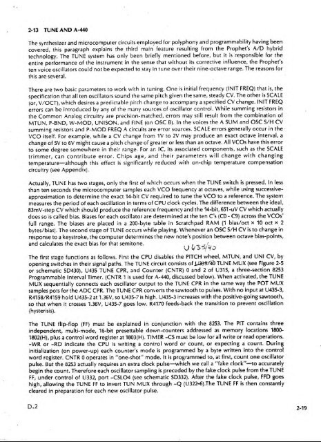
'i2-13 TUNE AND A-440The synthesizer and microcomputer circuits employed for polyphony and programmability having beencovered, this paragraph explains the third main feature resulting from the <strong>Prophet</strong>'s A/D hybridtechnology. The TUNE system has only been briefly mentioned before, but it is responsible for theentire performance of the instrument in the sense that without its corrective influence, the <strong>Prophet</strong>'sten voice oscillators could not be expected to stay in tune over their nine-octave range. The reasons forthis are several.There are two basic parameters to work with in tuning. One is initial frequency (INIT FREQ) that is, thespecification that all ten oscillators sound the same pitch given the same, steady CV. The other isSCALE(or, V/OCT), which desires a predictable pitch change to accompany a specified CV change. INIT FREQerrors can be introduced by any of the many sources of oscillator control. While summing resistors inthe Common Analog circuitry are precision-matched, errors may stillMTUN. P-BND, W-MOD, UNISON, and FINE (on OSC B).result from the combination ofIn the voices the A SUM and OSC S/H CVsumming resistors and P-MOD FREQ A circuits are error sources. SCALE errors generally occur in theVCO itself.For example, while a CV change from IV to 2V may produce an exact octave interval, achange of 5V to 6V might cause a pitch change of greater or less than an octave. All VCOs have this errorto some degree somewhere in their range. For an IC, its associated components, such as the SCALEtrimmer, can contribute error. Chips age, and their parameters will change with changingtemperature—although this effect is significantly reduced with on-chip temperature compensationcircuitry (see Appendix).Actually, TUNE has two stages, only the first of which occurs when the TUNE switch ispressed. In lessthan ten seconds the microcomputer samples each VCO frequency at octaves, while using successiveapproximationto determine the exact 14-bit CV required to tune the VCO to a reference. The systemmeasures the period of each oscillation in terms of CPU clock cycles. The difference between the ideal,83mV-step CV which should produce the reference frequency and the 14-bit, 651 -uV CV which actuallydoes so is called bias. Biases for each oscillator are determined at the ten C's (CO - C9) across the VCOs'full range. The biases are placed in a 200-byte table in Scratchpad RAM (1 bias/oct x 10 oct x 2bytes/bias). The second stage of TUNE occurs while playing. Whenever an OSC S/H CV is to change inresponse to a keystroke, the computer determines the new note's position between octave bias-points,and calculates the exact bias for that semitone.^, -? A'''The first stage functions as follows. First the CPU disables the PITCH wheel, MTUN, and UNI CV, byopening switches in their signal paths. The TUNE circuit consists of 1036^/40 TUNE MUX (see Figure 2-5or schematic SD430), U435 TUNE CPR, and Counter (CNTR) and 2 of U315, a three-section 8253Programmable Interval Timer. (CNTR 1 is used for A-440, discussed below). When activated, the TUNEMUX sequentially connects each oscillator output to the TUNE CPR in the same way the POT MUXsamples pots for the ADC CPR. The TUNE CPR converts the sawtooth to pulses. With no input at U435-3,R4158/R4159 hold U435-2 at 1.36V, so U435-7 isso that when it(hysterisis).high. U435-3 increases with the positive-going sawtooth,crosses 1.36V, U435-7 goes low. R4170 feeds-back the transition to prevent oscillationThe TUNE flip-flop (FF) must be explained in conjunction with the 8253. The PIT contains threeindependent, multi-mode, 16-bit presettable down-counters addressed as memory locations 1800-1802(H), plus a control word register at 1803(H). TIMER -CS must be low for all write or read operations.-WR or -RD indicate the CPU is writing a control word or count, or expecting a count. Duringinitialization (on power-up) each counter's mode is programmed by a byte written into the controlword register. CNTR operates in ''one-shot" mode. It is programmed to, at first, count one oscillatorpulse. But the 8253 actually requires an extra clock pulse—which we call a "fake clock"—to accuratelybegin the count. Therefore each oscillator sampling is preceded by the fake clock pulse from the TUNEFF,under control of U332, port -CSL04 (see schematic SD332). After the fake clock pulse, FFD goeshigh, allowing the TUNE FF to invert TUN MUX through -Q (U322-6).The TUNE FF iscleared in preparation for each new oscillator pulse.then constantlyD.2 2-19
the same CV and trigger pattern to the <strong>Prophet</strong>, which digitizes the SEQ CV IN for control of Voice 5.iWith CNTRenabled by CNTR EN at U332-5. OUTO (U315-10) goes low at the first oscillator edge fromthe TUNE CPR. U321-1 inverts this to a high which gales CNTR 2. CNTR 2 isclock cycles, so it decrements at the rate of 2.5 MHz. When CNTR reaches its terminal count, that is,programmed to count CPUwhen one pulse (iri addition to the fake clock) has been counted, OUTO goes high, stopping CNTR 2.CNTR 2's 16-blt register now represents the number of CPU clock cycles occuring during one period ofOSC lA's sawtooth. This number is compared to a reference. An oscillator that is too sharp will have alower count than the reference, and vice versa. As long asthe count and reference don't match, theCPU adjusts the OSC S/H CV and samples the sawtooth again. Successive approximation starts with theDAC MSB, setting each bit which does not cause the oscillator pitch to overshoot the reference.After tuning OSC 1 A at C3, the reference count ishalved to tune CA, since one cycle at C4 should takeexactly half the number of CPU clock cycles than at C3. For octaves C5 - C9, the cycle count in CNTRdoubled instead (2, 4, 8.. .32).the C3 -The CO- C2 biases are actually extrapolated from the curve suggested byC9 bias table, rather rhnn found by dir{?ct measurement because counting such low-frequencypulses would take an inconvenient amount of time.same way.The remaining oscillators are tuned in the4isWhen enabled by U332-12, CNTR 1 simply divides 2.5 MHz by 5682 to produce the 440-Hz square wavesummed into the AUD OUT stage (see SD430). To prevent noise, the A-440 input is grounded by U460-9when not inuse. by inverter-connected U461-9.2-14 SEQUENCER INTERFACEThe sequencer interface is intended for use with SCI's Model 800 Digital Sequencer, although thedesign is flexible enough to interface with many types and qualities of analog inputs. For sequencerecording the <strong>Prophet</strong> outputs the keyboard CV and a trigger pulse for the most recently played note inpolyphonic mode, and for the lowest note played in UNISON mode. To playback, the sequencer sendsThe <strong>Prophet</strong>'s sequencer output (record) circuitry isthe same as the synthesizer output circuitry. SEQICV OUT appears at S/H U350-7 before buffering by voltage follower U348-6 (see schematic SD333). TheSEQ TRIG OUT Isa bit latched by port -CSOH5, U340-2.The sequencer input (playback) circuitry is a bit more complex (see schematic SD332). ConnectingSEQUENCER.GATE IN closes a switch on J3 grounding U323-10. When port CSI1 is input, this low notifiesthe computer to process the two SEQ inputs. SEQ CV IN is assumed to be an analog voltage which slewsbetween its various values. The slew rate will vary with the type of sequencer (or other accessory).Ideally, the input device only produces its GATE once its CV output has fully stabilized. However, in theworst case some accessories will continue to slew after producing the GATE. For this reason the <strong>Prophet</strong>delays the SEQ GATE IN te allow SEQ CV IN time to settle,the CPU.by using the interrupt (-INT) feature ofIDuring initialization the Z-SO's interrupt mode programmed isso that a low on the -INT pin forces theprogram to restart at memory location 38(H) (when the interrupt has been software-enabled). This is thestarting address of the SEQ HANDLER subroutine. Initialization also clears the -INT through port-CSOL5. U331-12 inverts this -CS to +CLR INT which resets U330-4, making -Q high. U330-13, Q remainslow, being held reset by U331-4. When a GATE appears. U331-4 goes low and U331-2 goes high after a2-ms delay through R311/C316. This high clocks U330-3, producing the -INT pulse at U330-2.When it receives the -INT, the CPU completes its current instruction, placing the next instructionaddress and register statuses on the "stack", then enables the SEQ CV IN by latching EN SEQ throughport -C50H4, U339-2 (see schematic SD333). This bit closes switch U371-9, connecting the SEQ CV IN tothe ADC CPR. The SEQ CV is then determined through successive-approximation and stored in aScratchpad table for later addition to Voice 5. After the voltage isinterrupt. However, this time U330-13 goes high, gating voice 5, because U330-10 isprocessed, the CPU again clears thethe SEQ GATE IN through U331-4. When SEQ GATE IN turns off, U330-13 is again reset.being held low by2-20
- Page 1 and 2: ^^. ^ ^s .y ^,-j?^ ^^w^-^>&i^^^V^?v
- Page 3 and 4: PROPHET-5 SYNTHESIZERTECHNICAL MANU
- Page 5 and 6: iJTable of ContentsISECTION 1MECHAN
- Page 7 and 8: '1SECTION 1MECHANICAL1-0 GENERALThi
- Page 9 and 10: Raise the top panel assembly to ser
- Page 11 and 12: 1-5 PCB 1/2 CONTROL PANELSOnce PCB
- Page 13 and 14: Figure 1-5KEYBOARD REMOVAL1 -7/1 -8
- Page 15 and 16: TOADDITIONALVCOsTOADDITIONALENV GEN
- Page 17 and 18: 2-2 THE PROPHETThe Prophet is a sub
- Page 19 and 20: COMMON ANALOGVOICE(VOiCES e-5 ARE S
- Page 21 and 22: 'IAll processed CVs originate from
- Page 23 and 24: ajMim—2-8 AUDIO OUTPUTAs shown in
- Page 25 and 26: .'2-10 MICROPROCESSOR, MEMORY, AND
- Page 27 and 28: For troubleshooting, it should be e
- Page 29 and 30: 2-12 ADC, DAC, AND CV OUTPUTSThe DA
- Page 31: iirH- - jMg 1— -^ 'iVMUX, U201-3^
- Page 35 and 36: SECTION 3DOCUMENTS3-0 DOCUMENT LIST
- Page 37 and 38: TOP PANEL ASSEMBLY1CHASSiSLAST \NOT
- Page 39 and 40: TB/0i/20f 32 22 30 20 19 25 233 2 I
- Page 41 and 42: TBZOf/^fOtP^2C20ZTBZOI/IOl17FUT ATK
- Page 43 and 44: OA* Y*tMOlooMtt'O o)i:i'^.^^.1 I5-
- Page 45 and 46: —' i+6V+5d^1—+I5V+ SV+ V ff^ U3
- Page 47 and 48: 1+ I5V£/JJiJ-5|T> -TUNEWBOtWfOiAMP
- Page 50 and 51: P40I+I6V(TUNE MUX)P40iP40f3ft wMIK
- Page 52 and 53: + I5VOSCP40i^Q ^ |PMOPFR£QASFINAL
- Page 54 and 55: M+I5VP40/ x|5v301 K|%34^fM0O£WASR4
- Page 56 and 57: IU504ft50647C5042Z00|iFMCTBMtZCT2 1
- Page 58 and 59: Inpreparation for service, set up t
- Page 60 and 61: 4-2 OSCILLATOR B TESTSTEP MODULE CO
- Page 62 and 63: 4-S FILTER TEST.STEP'MODULE CONTROL
- Page 64 and 65: 4-8 POLY-MOD TEST—A.STEP MODULE C
- Page 66 and 67: i4-11 PITCH WHEEL TRIMThis trim rem
- Page 68 and 69: A)I4-16 VCO SCALE TRIMBE SURE RECOR
- Page 70 and 71: 4-19 FILTER ENVELOPE AMOUNT VCA BAL
- Page 72 and 73: 4-21 FINAL VGA BAL1. Switch PRESET
- Page 74 and 75: 115-3 PCB 3BT301 E-040L-\:!Oi 0-U45
- Page 76 and 77: I ]U374U375U376U377U37SU379U380U381
- Page 78 and 79: 1R419SR4199R4200R4201R4202R4203R420
- Page 80 and 81: 51» IR44S7/488 R-025R44S9 R-009R44
- Page 82 and 83:
kL096 E-066098 E-071100 E-078102 E-
- Page 84 and 85:
IJ310 M-156312 M-157314 M-158316 M-
- Page 86 and 87:
JJ51S R-161520 R--162522 R-163524 R
- Page 88 and 89:
FFFFDBKFETFFFILTFINFINEFOAFREQFSKFT
- Page 90 and 91:
11 IJSECTION 8THEORY8-0 INTRODUCTIO
- Page 92 and 93:
1 1for the 2 to 5-foot range. The c
- Page 94 and 95:
IiSECTION 9PRCX^RAMMING9-0 INTRODUC
- Page 96 and 97:
I3JIJThe Prophet will not accept st
- Page 98 and 99:
ByteByte 23Switch Bit (7)OSC A PULS
- Page 100 and 101:
t J IISECTION 10REVISION 3.1 and 3.
- Page 102 and 103:
I+ I5V+5dI^1-+5V 2'2pF+I6V+5V^^' U3
- Page 104 and 105:
T&=* PANEL ASSE^^mtYSAfKEYBOARD,'r-
- Page 106 and 107:
.^^'»_ u jj'/X H"r,P-*tQ( p5^f -^"
- Page 108 and 109:
4/J«-5[E> -TUNER57a12wzofwiOi^^^^^
- Page 110 and 111:
—T8502J/fRSOBWMfrS/IC5045.iiU502i
- Page 112 and 113:
^ 1 1 ;4 PINFigure II-OFigure11-TM1
- Page 114 and 115:
I 111-2 REVISION 3.0 MEMORY TESTRev
- Page 116 and 117:
Tr1 1-5 WHEEL BALANCE TRIM1. See pa
- Page 118 and 119:
SECTION 13PROPHET-5 REV 3.3 UPDATET
- Page 120 and 121:
iFigure 13-1PCB 3 TOP MODIFICATIONT
- Page 122 and 123:
T 1ttSillniiinMIttltltlltlillll^- ^
- Page 124 and 125:
i/*5-tft/jj4-y,6-C90H202 >7-CS0H5Q3
- Page 126 and 127:
'^'K'..v''
- Page 128 and 129:
tV t IEPROM1000.3.0V.8.0V.8.1V.8.21
- Page 130 and 131:
IJmemory interface1000.3.01000.3.11
- Page 132 and 133:
ittKRAM, non-volatile (NV)1000.3.01
- Page 134:
1voltage-current convertervoice ass


