Sequential Circuits Prophet-5 Service Manual - Audiofanzine
Sequential Circuits Prophet-5 Service Manual - Audiofanzine
Sequential Circuits Prophet-5 Service Manual - Audiofanzine

You also want an ePaper? Increase the reach of your titles
YUMPU automatically turns print PDFs into web optimized ePapers that Google loves.
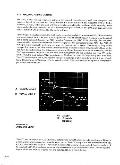
2-12 ADC, DAC, AND CV OUTPUTSThe DAC is the essential interface between the control potentiometers and microcomputer andbetween the microcomputer and the synthesizer. It is based on the 16-bit, integrated DAC-71-CSB-I.However, at most, 14 bits are used only for precisely controlling the oscillators while, normally, sevenbits provide adequate resolution for all other computer-processed CVs. The DACs full scale voltage is10.67V, but most CVs are limited to 10V by the software.JFor editing or manual operation, the DAC performs analog-to-digital conversion (ADC).' This isdone byoutputting one of 24 entries from a Scratchpad RAM table of pot settings, at the same time the actualpot isbeing sampled through the ADC "window" comparator (ADC CPR). (Actually, the 10-V DACrange is divided by two for comparison with 5V-range pots.) The comparator signals ADC HI or ADC LOif the pot wiper is actually set below or above the value of the converted table entry. As long as thevoltages don't match, the table value is decremented or incremented until they do match. Once all thepots have been checked, a few adjustments are made (depending on the mode of operation), and theDAC again converts the pot values, this time distributing them and the oscillator and filter CVs to thesynth. Thus, the DAC output, Vdac, steps between 62 values (24 pots + 38 CVs) (during each 6-ms loop.The POT MUX output, Vmux, assumes the value of the settings of ail 24 pots during the first part of eachloop. This is shown in Waveform 2-1a. In Waveform 2-1b, Vdac is shown assuming the 24 comparativepot values and the 38 CVs.A VMUX, U365-9B VDAC, U364-7V:H:2V/div.5 ms/div(approx.)Waveform 2-1VMUX AND VDACThe POT MUX shown is on SD231. Basically, data latched by U211 selects (or, addresses) one of 24 pots ata time, whose wiper voltage becomes the Vmux sent to the ADC comparator. The address latch bits QO,Q1, Q5 have a decimal value 0-7. Waveform 2-2 shows QO toggling when clocked. Applied to the A, B,C, inputs of U201-03, these bits simultaneously select one of eight inputs on each 4051. When high the Iinputs inhibit the 4051; so to select just one pot, Q2, Q3, or Q4 must be low.2-16